Using the finite - time disturbance observer (FTO) for robotic manipulator Almega 16
This paper presents build a finite time observator (FTO) and applies it to the
Almega16 robot motion system. The main content of the article is to design a
FTO so that the observation of the external noise of the Almega16 robot motion
system will converge to the desired true value over a period of time. finite, is
done by estimating the external noise quantities and then feeding them into the
available Robot controller. The advantage when applying the FTO disturbance
monitor is that it is possible to eliminate the inverse inertia matrix component in
the dynamic equation. The results achieved showed that the Almega16 robot
movement system ensures that the errors of the rotating joints quickly reach
zero with a small transition time, making the closed system stable according to
Lyapunov standards
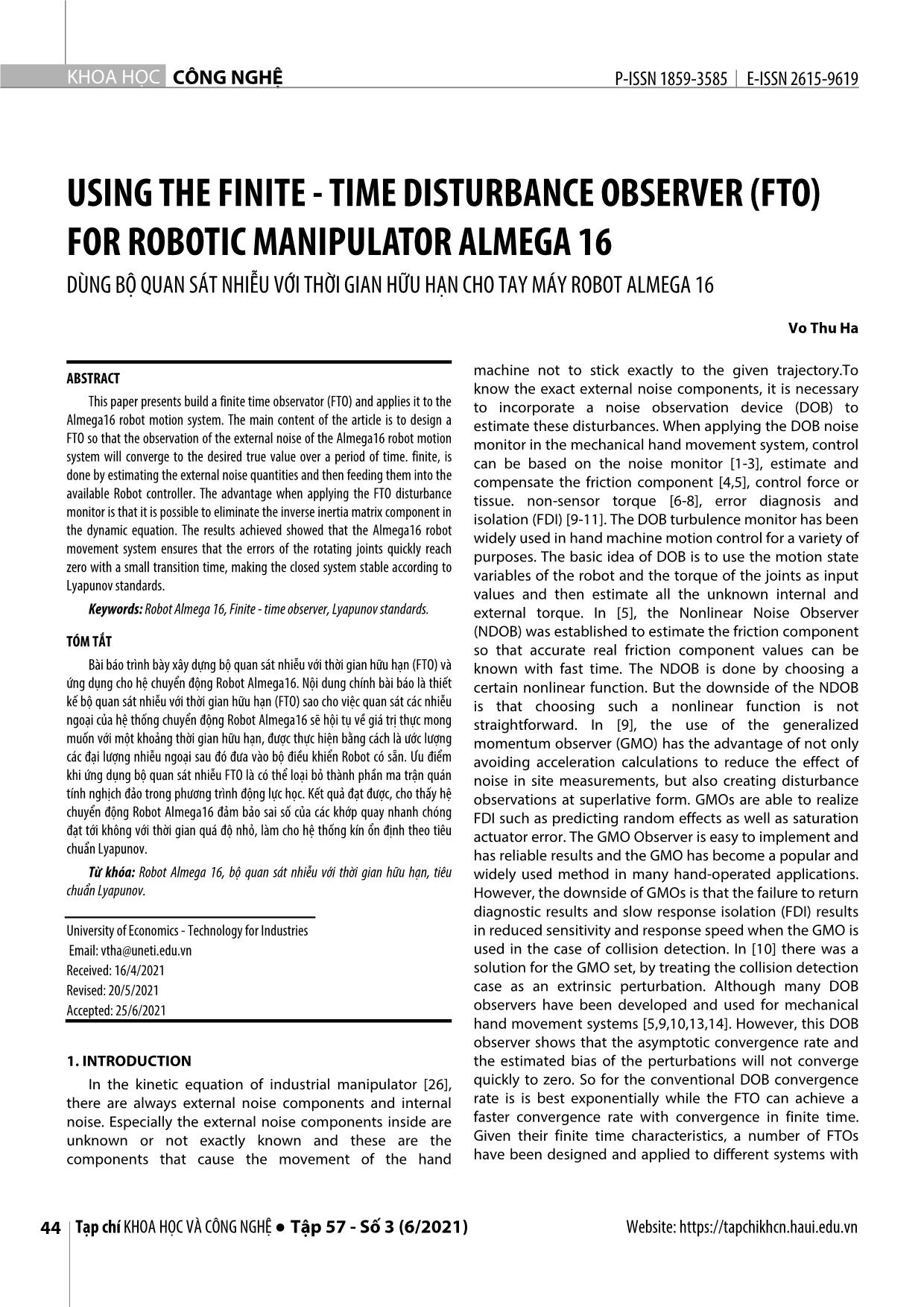
Trang 1
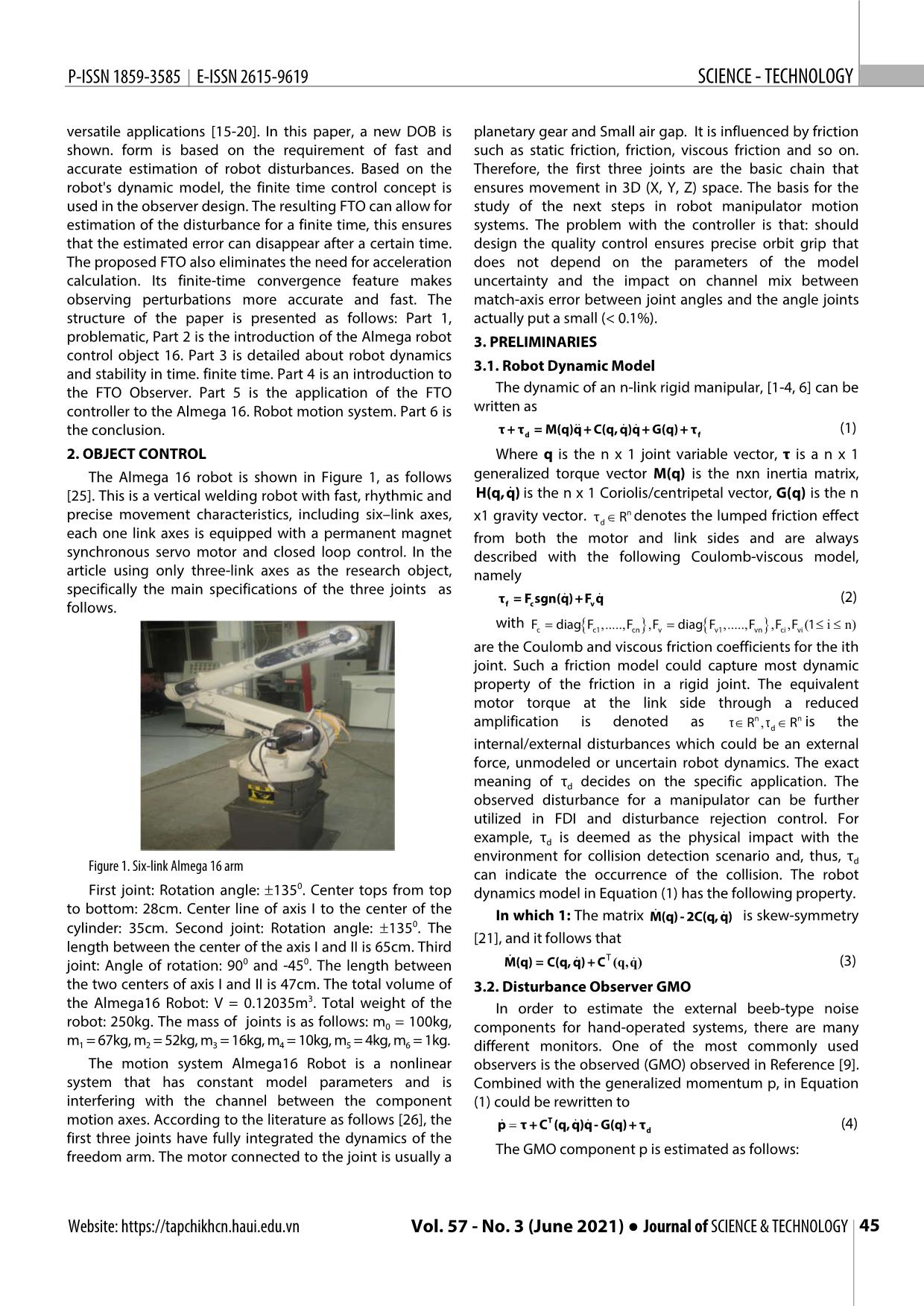
Trang 2
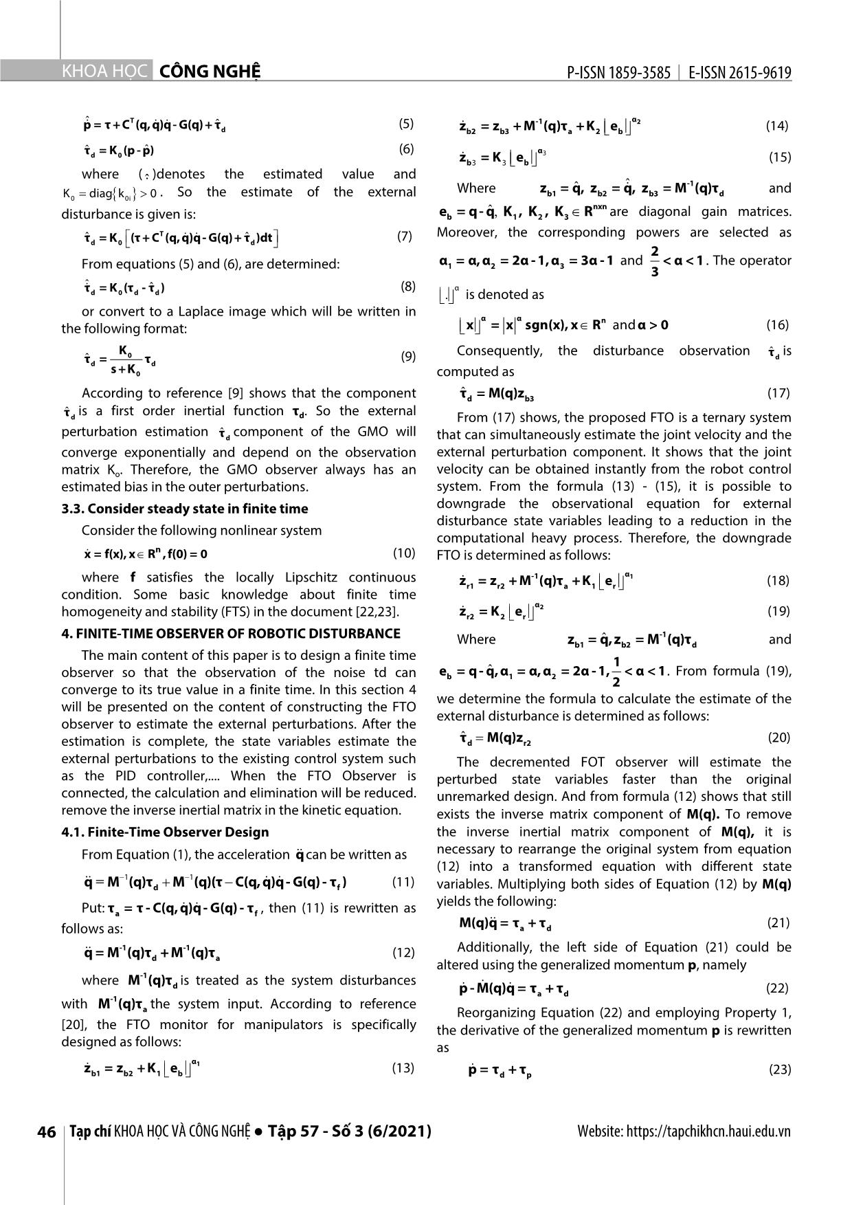
Trang 3
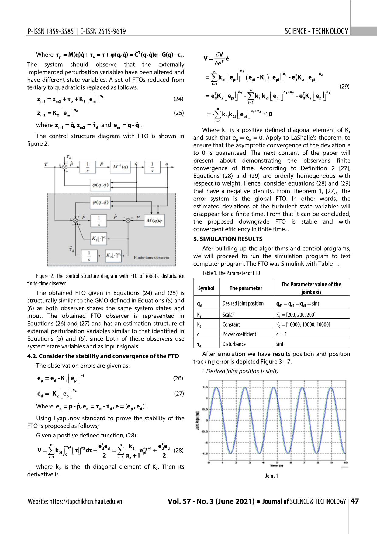
Trang 4
Trang 5
Trang 6
Tóm tắt nội dung tài liệu: Using the finite - time disturbance observer (FTO) for robotic manipulator Almega 16
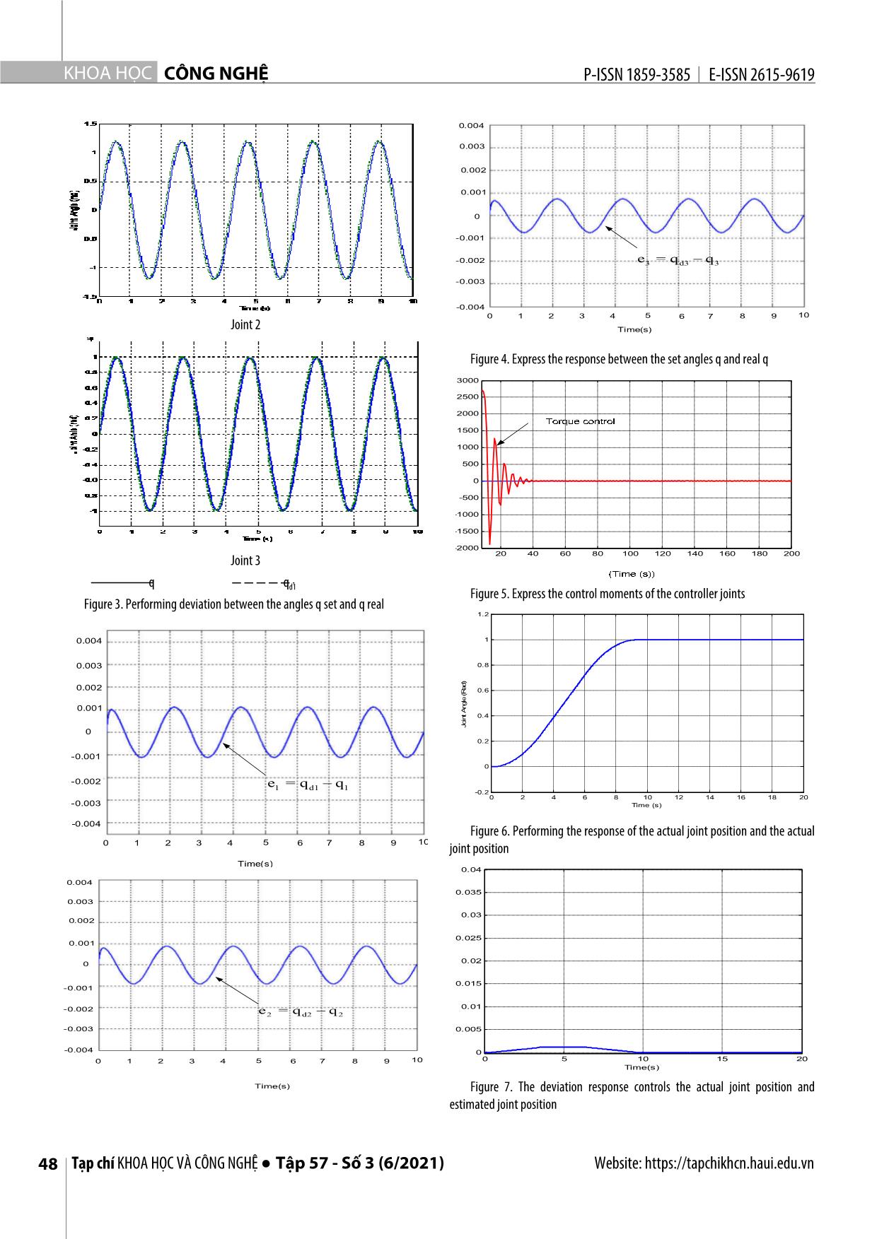
irst three joints have fully integrated the dynamics of the freedom arm. The motor connected to the joint is usually a The GMO component p is estimated as follows: Website: https://tapchikhcn.haui.edu.vn Vol. 57 - No. 3 (June 2021) ● Journal of SCIENCE & TECHNOLOGY 45 KHOA H ỌC CÔNG NGHỆ P-ISSN 1859-3585 E-ISSN 2615-9619 pˆ = τ +CT (q,q)q- G(q)+ τˆ (5) -1 α2 d zb2 = z b3 + M (q)τ a +K 2 e b (14) τˆ = K (p - p)ˆ (6) α3 d 0 zb3 = K 3 e b (15) where ( . )denotes the estimated value and ˆ ˆ -1 Where zb1 = q,ˆ z b2 = q, z b3 = M (q)τ d and K0 diag k 0i 0 . So the estimate of the external ˆ nxn disturbance is given is: e=q-qK,K,Kb, 1 2 3 R are diagonal gain matrices. ˆ T ˆ (7) Moreover, the corresponding powers are selected as τd = K 0 (τ + C (q,q)q- G(q)+ τ d )dt 2 From equations (5) and (6), are determined: α1 =α,α 2 =2α-1,α 3 =3α-1 and < α < 1. The operator 3 τˆ = K (τ - τˆ ) (8) α d 0 d d . is denoted as or convert to a Laplace image which will be written in α α n the following format: x = x sgn(x), x R and α > 0 (16) K 0 Consequently, the disturbance observation τˆ d is τˆ d = τ d (9) s +K0 computed as According to reference [9] shows that the component τˆ d = M(q)z b3 (17) τˆ is a first order inertial function τ . So the external d d From (17) shows, the proposed FTO is a ternary system perturbation estimation τˆ d component of the GMO will that can simultaneously estimate the joint velocity and the converge exponentially and depend on the observation external perturbation component. It shows that the joint matrix Ko. Therefore, the GMO observer always has an velocity can be obtained instantly from the robot control estimated bias in the outer perturbations. system. From the formula (13) - (15), it is possible to 3.3. Consider steady state in finite time downgrade the observational equation for external disturbance state variables leading to a reduction in the Consider the following nonlinear system computational heavy process. Therefore, the downgrade x = f(x), x Rn ,f(0) = 0 (10) FTO is determined as follows: where f satisfies the locally Lipschitz continuous -1 α1 zr1 = z r2 + M (q)τ a +K 1 e r (18) condition. Some basic knowledge about finite time α2 homogeneity and stability (FTS) in the document [22,23]. zr2 = K 2 e r (19) 4. FINITE-TIME OBSERVER OF ROBOTIC DISTURBANCE -1 Where zb1 = q,zˆ b2 = M (q)τ d and The main content of this paper is to design a finite time 1 observer so that the observation of the noise td can e = q- q,ˆ α = α, α = 2α -1, < α < 1. From formula (19), b 1 2 2 converge to its true value in a finite time. In this section 4 we determine the formula to calculate the estimate of the will be presented on the content of constructing the FTO external disturbance is determined as follows: observer to estimate the external perturbations. After the ˆ estimation is complete, the state variables estimate the τd M(q)z r2 (20) external perturbations to the existing control system such The decremented FOT observer will estimate the as the PID controller,.... When the FTO Observer is perturbed state variables faster than the original connected, the calculation and elimination will be reduced. unremarked design. And from formula (12) shows that still remove the inverse inertial matrix in the kinetic equation. exists the inverse matrix component of M(q). To remove 4.1. Finite-Time Observer Design the inverse inertial matrix component of M(q), it is From Equation (1), the acceleration q can be written as necessary to rearrange the original system from equation (12) into a transformed equation with different state 1 1 q= M (q)τd M (q)(τ C(q,q)q- G(q) - τ f ) (11) variables. Multiplying both sides of Equation (12) by M(q) yields the following: Put: τa = τ - C(q, q)q- G(q) - τ f , then (11) is rewritten as M(q)q = τ + τ (21) follows as: a d q = M-1 (q)τ +M -1 (q)τ (12) Additionally, the left side of Equation (21) could be d a altered using the generalized momentum p, namely -1 where M (q)τd is treated as the system disturbances p - M(q)q = τa + τ d (22) with M-1 (q)τ the system input. According to reference a Reorganizing Equation (22) and employing Property 1, [20], the FTO monitor for manipulators is specifically the derivative of the generalized momentum p is rewritten designed as follows: as α1 zb1 = z b2 +K 1 e b (13) p = τd + τ p (23) 46 Tạp chí KHOA HỌC VÀ CÔNG NGHỆ ● Tập 57 - Số 3 (6/2021) Website: https://tapchikhcn.haui.edu.vn P-ISSN 1859-3585 E-ISSN 2615-9619 SCIENCE - TECHNOLOGY Where τ = M(q)q+ τ = τ +φ(q,q) = CT (q,q)q- G(q) - τ . V p a f V =T e The system should observe that the externally e n α2 implemented perturbation variables have been altered and α α 1T 2 have different state variables. A set of FTOs reduced from = k2i e pi e di - K 1 e pi - e d K 2 e pi i=1 (29) tertiary to quadratic is replaced as follows: n TTα2 α 1 +α 2 α 2 α1 = e K e - k k e - e K e z = z + τ + K e (24) d 2 pi 1i 2i pi d 2 pi m1 m2 p 1 m i=1 n α α +α z = K e 2 (25) 1 2 m2 2 m = - k1i k 2i e pi 0 i=1 ˆ ˆ where zm1 = q, z m2 = τˆ d and em = q- q . Where k1i is a positive defined diagonal element of K1 The control structure diagram with FTO is shown in and such that ep = ed = 0. Apply to LaShalle's theorem, to figure 2. ensure that the asymptotic convergence of the deviation e to 0 is guaranteed. The next content of the paper will present about demonstrating the observer's finite convergence of time. According to Definition 2 [27], Equations (28) and (29) are orderly homogeneous with respect to weight. Hence, consider equations (28) and (29) that have a negative identity. From Theorem 1, [27], the error system is the global FTO. In other words, the estimated deviations of the turbulent state variables will disappear for a finite time. From that it can be concluded, the proposed downgrade FTO is stable and with convergent efficiency in finite time... 5. SIMULATION RESULTS Afer building up the algorithms and control programs, we will proceed to run the simulation program to test computer program. The FTO was Simulink with Table 1. Figure 2. The control structure diagram with FTO of robotic disturbance Table 1. The Parameter of FTO finite-time observer The Parameter value of the Symbol The parameter The obtained FTO given in Equations (24) and (25) is joint axis structurally similar to the GMO defined in Equations (5) and q Desired joint position q = q = q = sint (6) as both observer shares the same system states and d d1 d2 d3 input. The obtained FTO observer is represented in K1 Scalar K1 = [200, 200, 200] Equations (26) and (27) and has an estimation structure of K2 Constant K2 = [10000, 10000, 10000] external perturbation variables similar to that identified in α Power coefficient α = 1 Equations (5) and (6), since both of these observers use system state variables and as input signals. τd Disturbance sint 4.2. Consider the stability and convergence of the FTO After simulation we have results position and position tracking error is depicted Figure 3÷ 7. The observation errors are given as: α * Desired joint position is sin(t) 1 ep = e d -K 1 e p (26) α 2 ed = -K 2 e p (27) Where ep = p -p,eˆ d = τ d -τˆ d ,e=[e p ,e] d . Using Lyapunov standard to prove the stability of the FTO is proposed as follows; Given a positive defined function, (28): nTT n epi α e ek e e V = k τ 2 dτ +d d =2i eα2 +1 + d d (28) 2i 0 pi i=12 i=1 α2 +1 2 where k2i is the ith diagonal element of K2. Then its derivative is Joint 1 Website: https://tapchikhcn.haui.edu.vn Vol. 57 - No. 3 (June 2021) ● Journal of SCIENCE & TECHNOLOGY 47 KHOA H ỌC CÔNG NGHỆ P-ISSN 1859-3585 E-ISSN 2615-9619 0.004 0.003 0.002 0.001 0 -0.001 -0.002 e = q q 3e2 = d3q d2 3 q 2 -0.003 -0.004 0 1 2 3 4 5 6 7 8 9 10 Joint 2 Time(s) Figure 4. Express the response between the set angles q and real q 3000 2500 2000 1500 1000 500 0 -500 -1000 -1500 -2000 Joint 3 20 40 60 80 100 120 140 160 180 200 q q d1 Figure 5. Express the control moments of the controller joints Figure 3. Performing deviation between the angles q set and q real 1.2 0.004 1 0.003 0.8 0.002 0.6 0.001 0.4 Joint Angle (Rad) (Rad) Angle Joint 0 0.2 -0.001 0 -0.002 e1 = q d1 q 1 -0.2 0 2 4 6 8 10 12 14 16 18 20 -0.003 Time (s) -0.004 Figure 6. Performing the response of the actual joint position and the actual 0 1 2 3 4 5 6 7 8 9 10 joint position Time(s) 0.04 0.004 0.035 0.003 0.03 0.002 0.025 0.001 0 0.02 0.015 -0.001 -0.002 0.01 e2 = q d2 q 2 -0.003 0.005 -0.004 0 0 1 2 3 4 5 6 7 8 9 10 0 5 10 15 20 Time(s) Time(s) Figure 7. The deviation response controls the actual joint position and estimated joint position 48 Tạp chí KHOA HỌC VÀ CÔNG NGHỆ ● Tập 57 - Số 3 (6/2021) Website: https://tapchikhcn.haui.edu.vn P-ISSN 1859-3585 E-ISSN 2615-9619 SCIENCE - TECHNOLOGY Comment: The simulation results of the real state and [11]. Haddadin S., De Luca A., Albu-Schäffer A., 2017. Robot collisions: A the above estimate prove that the synthesized FTO survey on detection, isolation, and identification. IEEE Trans. Robot, 33, 1292– observer is correct, showing that the joints of the Almega 1312. 16 robot are good with small setting time, less oscillation, [12]. Cho C.N., Kim J.H., Kim Y.L., Song J.B., Kyung J.H., 2012. Collision over-adjustment. detection algorithm to distinguish between intended contact and unexpected 6. CONCLUSION collision. Adv. Robot, 26, 1825–1840. The order reduction FTO has omitted acceleration and [13]. Mohammadi A., Tavakoli M., Marquez H.J., Hashemzadeh F., 2013. inverse matrix matrix, resulting in the FTO making the Nonlinear disturbance observer design for robotic manipulators. Control Eng. estimation deviations converge to 0 in a finite time. Pract., 21, 253–267. Although FTO has a more complex formula and thus the [14]. Nikoobin A., Haghighi R., 2009. Lyapunov-based nonlinear disturbance calculation time increases slightly compared to other observer for serial n-link robot manipulators. J. Intell. Robot. Syst., 55, 135–153. observers. The theory and simulation results show that [15]. Menard T., Moulay E., Perruquetti W., 2010. A global high-gain finite- using the FTO observatory to estimate the perturbation time observer. IEEE Trans. Autom. Control, 55, 1500–1506. components outside the Almega 16 robot motion system [16]. Lopez-Ramirez F., Polyakov A., Efimov D., Perruquetti W., 2018. Finite- has ensured the real joint position closely follows the time and fixed-time observer design: Implicit Lyapunov function approach. estimated joint position and ensures the actual matching Automatica, 87, 52–60. position is closely related to the matching position with small error. [17]. Menard T., Moulay E., Perruquetti W., 2017. Fixed-time observer with simple gains for uncertain systems. Automatica, 81, 438–446. [18]. Shen Y., Xia X., 2008. Semi-global finite-time observers for nonlinear systems. Automatica, 44, 3152–3156. REFERENCES [19]. Shtessel Y.B., Shkolnikov I.A., Levant A., 2007. Smooth second-order [1]. Pi Y., Wang X., 2010. Observer-based cascade control of a 6-DOF parallel sliding modes: Missile guidance application. Automatica, 43, 1470–1476. hydraulic manipulator in joint space coordinate. Mechatronics, 20, 648–655. [20]. Perruquetti W., Floquet T., Moulay E., 2008. Finite-time observers: [2]. Sahabi M.E., Li G., Wang X., Li S., 2016. Disturbance Compensation Based Application to secure communication. IEEE Trans. Autom. Control, 53, 356–360. Finite-Time Tracking Control of Rigid Manipulator. Math. Probl. Eng. 2016, [21]. Siciliano B., Sciavicco L., Villani L., Oriolo G., 2010. Robotics: Modelling, 2034795. Planning and Control. Springer Science & Business Media: Berlin/Heidelberg, [3]. Chen W.H., Yang J., Guo L., Li S., 2016. Disturbance-observer-based Germany. control and related methods-An overview. IEEE Trans. Ind. Electron., 63, 1083– [22]. Bhat S.P., Bernstein D.S., 2000. Finite-time stability of continuous 1095. autonomous systems. SIAM J. Control Optim., 38, 751–766. [4]. Bona B., Indri M., 2005. Friction compensation in robotics: An overview. [23]. Bhat S.P., Bernstein D.S., 2005. Geometric homogeneity with In Proceedings of the 44th IEEE Conference on Decision and Control, Seville, applications to finite-time stability. Math. Control. Signals Syst., 17, 101–127. Spain, pp. 4360–4367. [24]. Bacciotti A., Rosier L., 2006. Liapunov Functions and Stability in Control [5]. Chen W.H., Ballance D.J., Gawthrop P.J., O’Reilly J., 2000. A nonlinear Theory. Springer Science & Business Media: Berlin/Heidelberg, Germany. disturbance observer for robotic manipulators. IEEE Trans. Ind. Electron., 47, 932– 938. [25]. Ha V. T, 2012. Some control solutions aim to improve the quality of industrial hand motions. Ph.D. thesis, Hanoi University of Science and [6]. Magrini E., Flacco F., De Luca A., 2015. Control of generalized contact Technology. motion and force in physical human-robot interaction. In Proceedings of the 2015 IEEE International Conference on Robotics and Automation (ICRA), Seattle, WA, [26]. Neil M., Frank L.L., 2004. Robot Manipulator Control Theory and USA, pp. 2298–2304. Practice. Marcel Dekker. [7]. Magrini E., De Luca A., 2016. Hybrid force/velocity control for physical [27]. Pengfei Cao, Yahui Gan, Xianzhong Dai, 2019. Finite-Time Disturbance human-robot collaboration tasks. In Proceedings of the 2016 IEEE/RSJ Observer for Robotic Manipulators.Sensors (Basel), 19(8):1943. doi: International Conference on Intelligent Robots and Systems (IROS), Daejeon, 10.3390/s19081943. Korea, pp. 857–863. [8]. Gaz C., Magrini E., De Luca A., 2018. A model-based residual approach for human-robot collaboration during manual polishing operations. Mechatronics 55, THÔNG TIN TÁC GIẢ 234–247. Võ Thu Hà [9]. De Luca A., Mattone R., 2003. Actuator failure detection and isolation Trường Đại học Kinh tế - Kỹ thuật Công nghiệp using generalized momenta. In Proceedings of the IEEE International Conference on Robotics and Automation, Taipei, Taiwan, Volume 1, pp. 634–639. [10]. Ren T., Dong Y., Wu D., Chen K., 2018. Collision detection and identification for robot manipulators based on extended state observer. Control Eng. Pract., 79, 144–153. Website: https://tapchikhcn.haui.edu.vn Vol. 57 - No. 3 (June 2021) ● Journal of SCIENCE & TECHNOLOGY 49
File đính kèm:
 using_the_finite_time_disturbance_observer_fto_for_robotic_m.pdf

