Anten tái cấu hình theo giản đồ bức xạ và tần số sử dụng chuỗi padovan
Nội dung bài báo đề xuất một cấu trúc anten đa tái cấu hình: vừa có thể tái cấu hình theo giản đồ
bức xạ vừa có thể tái cấu hình theo tần số dựa trên các trạng thái bật – tắt khác nhau của bốn diode
PIN. Để làm được điều này, thiết kế anten được biến đổi theo hình vuông Padovan với 9 phần tử
trên mặt bức xạ và bốn phần tử trên mặt phẳng đất. Anten thu được có thể tái cấu hình theo giản
đồ bức xạ tại hai phương +520 và 270, tái cấu hình theo tần số từ 5Ghz đến 18.74GHz với kích
thước tổng thể khá nhỏ, đạt 44.44 x 35 x 1.52 mm3. Bên cạnh đó, các tham số quan trọng khác của
anten tái cấu hình như hiệu suất và băng thông thu được khá tốt ở phần lớn các tần số cộng hưởng
của anten.
Trang 1
Trang 2
Trang 3
Trang 4
Trang 5
Trang 6
Trang 7

Trang 8

Trang 9
Tóm tắt nội dung tài liệu: Anten tái cấu hình theo giản đồ bức xạ và tần số sử dụng chuỗi padovan
ble radiation patterns among all
 Số 25 9
TẠP CHÍ KHOA HỌC VÀ CÔNG NGHỆ NĂNG LƯỢNG - TRƯỜNG ĐẠI HỌC ĐIỆN LỰC
(ISSN: 1859 - 4557)
multiple frequency bands, productive follows. In Part 2, the antenna design is
utilization of electromagnetic range, and presented. The simulated and analysis are
frequency discernment, decreasing the co- studied in Part 3. Finally, Part 4 concludes
channel interference and jamming [1]. the study.
Only in 2018-2019, a score of researches
about reconfigurable antennas have been 2. ANTENNA DESIGN
reported with different variations such 2.1. Padovan sequence
as frequency reconfigurable [2]-[7],
 Unlike Fibonacci – golden ratio on the 2D
radiation pattern reconfigurable [8-15]. In
 dimension, the Padovan sequence that is a
[9], a wideband antenna was reconfigured
 golden ratio on the 3D dimensions is set
radiation pattern by G. Jin et al. The
 through a cubic function. The Padovan
antenna uses four diodes to change to four
different directions but the average sequence is defined by basic number
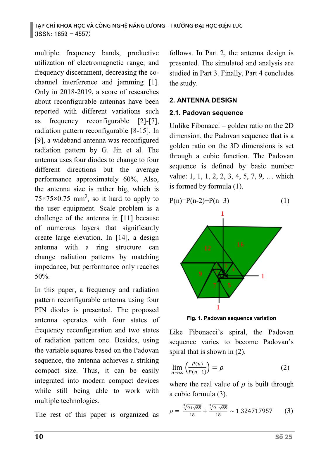
performance approximately 60%. Also, value: 1, 1, 1, 2, 2, 3, 4, 5, 7, 9,  which
the antenna size is rather big, which is is formed by formula (1).
 3
75×75×0.75 mm , so it hard to apply to P(n)=P(n-2)+P(n 3) (1)
the user equipment. Scale problem is a
challenge of the antenna in [11] because
of numerous layers that significantly
create large elevation. In [14], a design
antenna with a ring structure can
change radiation patterns by matching
impedance, but performance only reaches
50%.
In this paper, a frequency and radiation
pattern reconfigurable antenna using four
PIN diodes is presented. The proposed
antenna operates with four states of Fig. 1. Padovan sequence variation
frequency reconfiguration and two states Like Fibonacci’s spiral, the Padovan
of radiation pattern one. Besides, using sequence varies to become Padovan’s
the variable squares based on the Padovan spiral that is shown in (2).
sequence, the antenna achieves a striking 푃(푛)
 lim ( ) = 휌 (2)
compact size. Thus, it can be easily 푛→∞ 푃(푛−1)
integrated into modern compact devices where the real value of 휌 is built through
while still being able to work with a cubic formula (3).
multiple technologies.
 3 3
 √9+ 69 √9− 69
 휌 = √ + √ ~ 1.324717957 (3)
The rest of this paper is organized as 18 18
10 Số 25
 TẠP CHÍ KHOA HỌC VÀ CÔNG NGHỆ NĂNG LƯỢNG - TRƯỜNG ĐẠI HỌC ĐIỆN LỰC
 (ISSN: 1859 - 4557)
2.2. Antenna structure Table 1. Parameters and their dimensions (mm)
2.2.1. Antenna using Padovan Parameter Value Parameter Value
sequence W 35 P2 4
 44.44 6
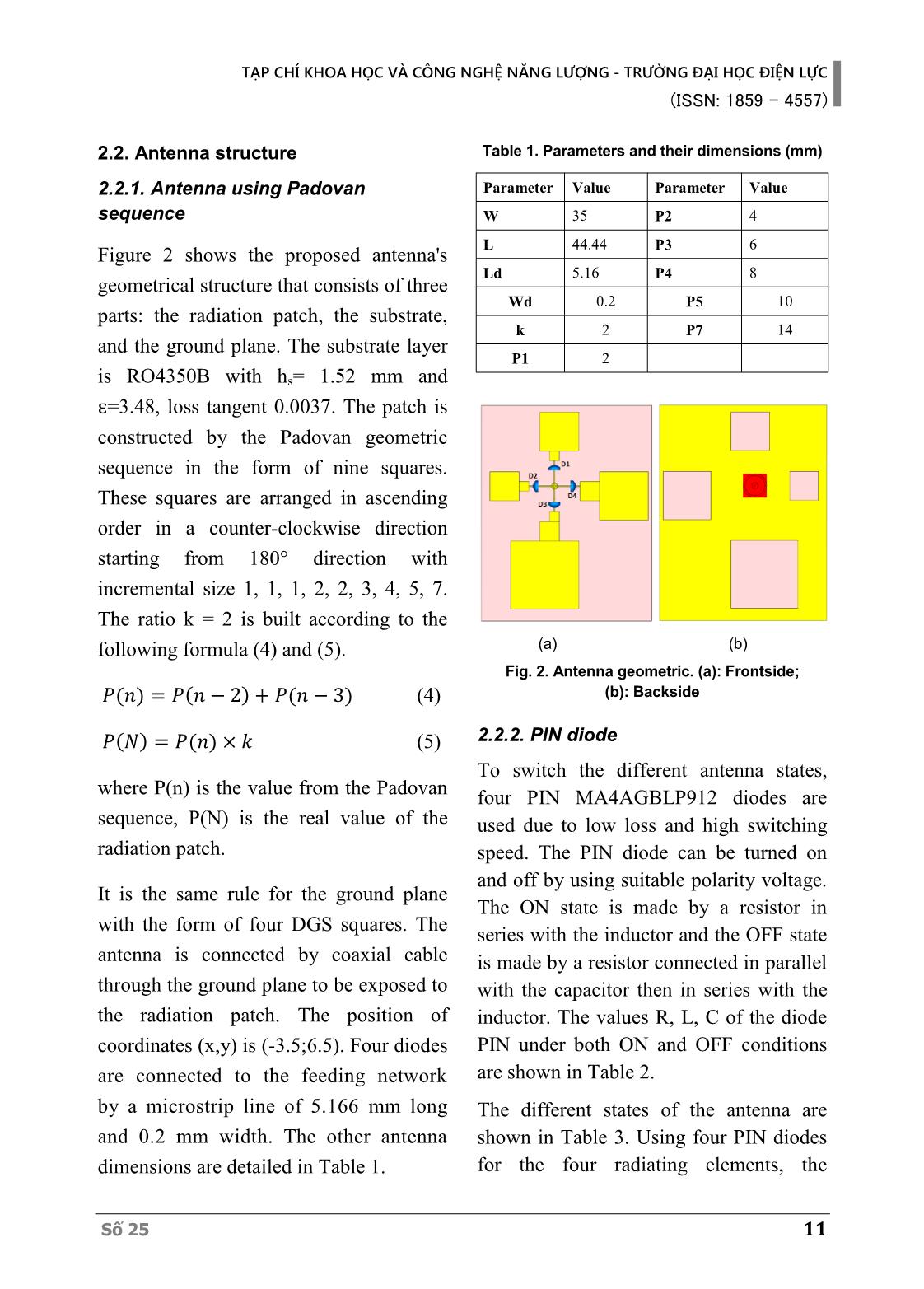
Figure 2 shows the proposed antenna's L P3
 Ld 5.16 P4 8
geometrical structure that consists of three
 Wd 0.2 P5 10
parts: the radiation patch, the substrate,
 k 2 P7 14
and the ground plane. The substrate layer
 P1 2
is RO4350B with hs= 1.52 mm and
ԑ=3.48, loss tangent 0.0037. The patch is
constructed by the Padovan geometric
sequence in the form of nine squares.
These squares are arranged in ascending
order in a counter-clockwise direction
starting from 180° direction with
incremental size 1, 1, 1, 2, 2, 3, 4, 5, 7.
The ratio k = 2 is built according to the
following formula (4) and (5). (a) (b)
 Fig. 2. Antenna geometric. (a): Frontside;
 푃(푛) = 푃(푛 − 2) + 푃(푛 − 3) (4) (b): Backside
 푃( ) = 푃(푛) × (5) 2.2.2. PIN diode
 To switch the different antenna states,
where P(n) is the value from the Padovan four PIN MA4AGBLP912 diodes are
sequence, P(N) is the real value of the used due to low loss and high switching
radiation patch. speed. The PIN diode can be turned on
 and off by using suitable polarity voltage.
It is the same rule for the ground plane
 The ON state is made by a resistor in
with the form of four DGS squares. The
 series with the inductor and the OFF state
antenna is connected by coaxial cable is made by a resistor connected in parallel
through the ground plane to be exposed to with the capacitor then in series with the
the radiation patch. The position of inductor. The values R, L, C of the diode
coordinates (x,y) is (-3.5;6.5). Four diodes PIN under both ON and OFF conditions
are connected to the feeding network are shown in Table 2.
by a microstrip line of 5.166 mm long The different states of the antenna are
and 0.2 mm width. The other antenna shown in Table 3. Using four PIN diodes
dimensions are detailed in Table 1. for the four radiating elements, the
Số 25 11
TẠP CHÍ KHOA HỌC VÀ CÔNG NGHỆ NĂNG LƯỢNG - TRƯỜNG ĐẠI HỌC ĐIỆN LỰC
(ISSN: 1859 - 4557)
antenna can resonate at the respective S11 parameter in different states of
frequencies while maintaining the same the switch using the PIN diode
direction of the radiation plot. Besides, at corresponding to the 2D radiation
a defined resonant frequency, the antenna patterns. Part 3.1 presents the frequencies
will also have different radiation of the reconfigured band while keeping
directions based on the state of the diode the radiation intact. Section 3.2 analyzes
is activated. the radiation pattern reconfiguration of
 the proposed antenna.
 3.1. Frequency reconfiguration
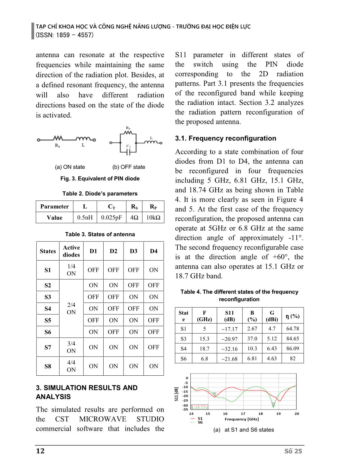
 According to a state combination of four
 diodes from D1 to D4, the antenna can
 (a) ON state (b) OFF state
 be reconfigured in four frequencies
 Fig. 3. Equivalent of PIN diode including 5 GHz, 6.81 GHz, 15.1 GHz,
 and 18.74 GHz as being shown in Table
 Table 2. Diode’s parameters
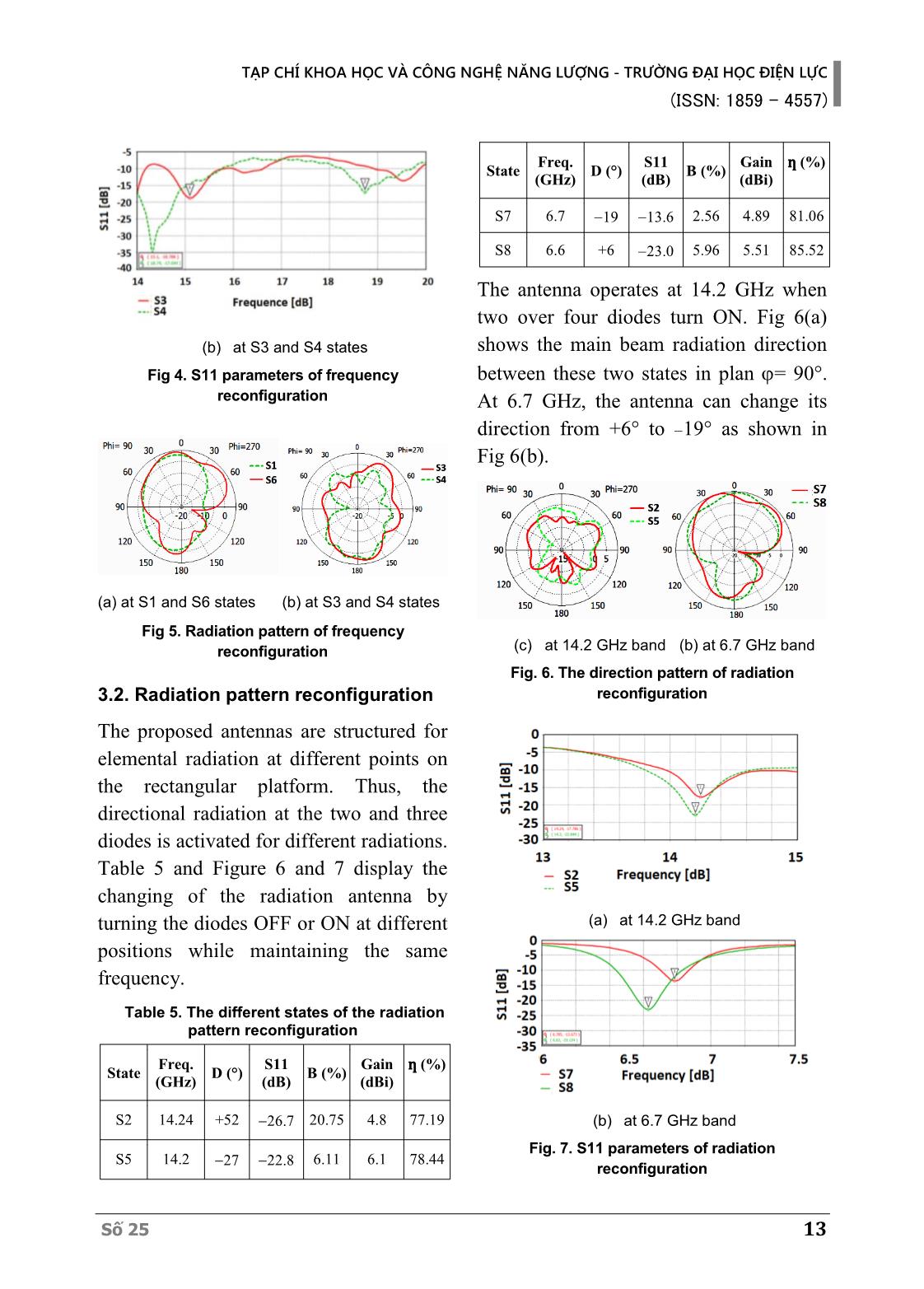
 4. It is more clearly as seen in Figure 4
 Parameter L CT RS RP and 5. At the first case of the frequency
 Value 0.5nH 0.025pF 4Ω 10kΩ reconfiguration, the proposed antenna can
 operate at 5GHz or 6.8 GHz at the same
 Table 3. States of antenna direction angle of approximately -11°.
 Active The second frequency reconfigurable case
 States D1 D2 D3 D4
 diodes is at the direction angle of +60°, the
 1/4
 S1 OFF OFF OFF ON antenna can also operates at 15.1 GHz or
 ON 18.7 GHz band.
 S2 ON ON OFF OFF
 Table 4. The different states of the frequency
 S3 OFF OFF ON ON reconfiguration
 2/4
 S4 ON OFF OFF ON
 ON Stat F S11 B G
 ƞ (%)
 S5 OFF ON ON OFF e (GHz) (dB) (%) (dBi)
 S1 5 2.67 4.7 64.78
 S6 ON OFF ON OFF 17.17
 S3 15.3 20.97 37.0 5.12 84.65
 3/4
 S7 ON ON ON OFF
 ON S4 18.7 32.16 10.3 6.43 86.09
 S6 6.8 21.68 6.81 4.63 82
 4/4
 S8 ON ON ON ON
 ON
3. SIMULATION RESULTS AND
ANALYSIS
The simulated results are performed on
the CST MICROWAVE STUDIO
commercial software that includes the (a) at S1 and S6 states
12 Số 25
 TẠP CHÍ KHOA HỌC VÀ CÔNG NGHỆ NĂNG LƯỢNG - TRƯỜNG ĐẠI HỌC ĐIỆN LỰC
 (ISSN: 1859 - 4557)
 Freq. S11 Gain ƞ (%)
 State D (°) B (%)
 (GHz) (dB) (dBi)
 S7 6.7 19 13.6 2.56 4.89 81.06
 S8 6.6 +6 23.0 5.96 5.51 85.52
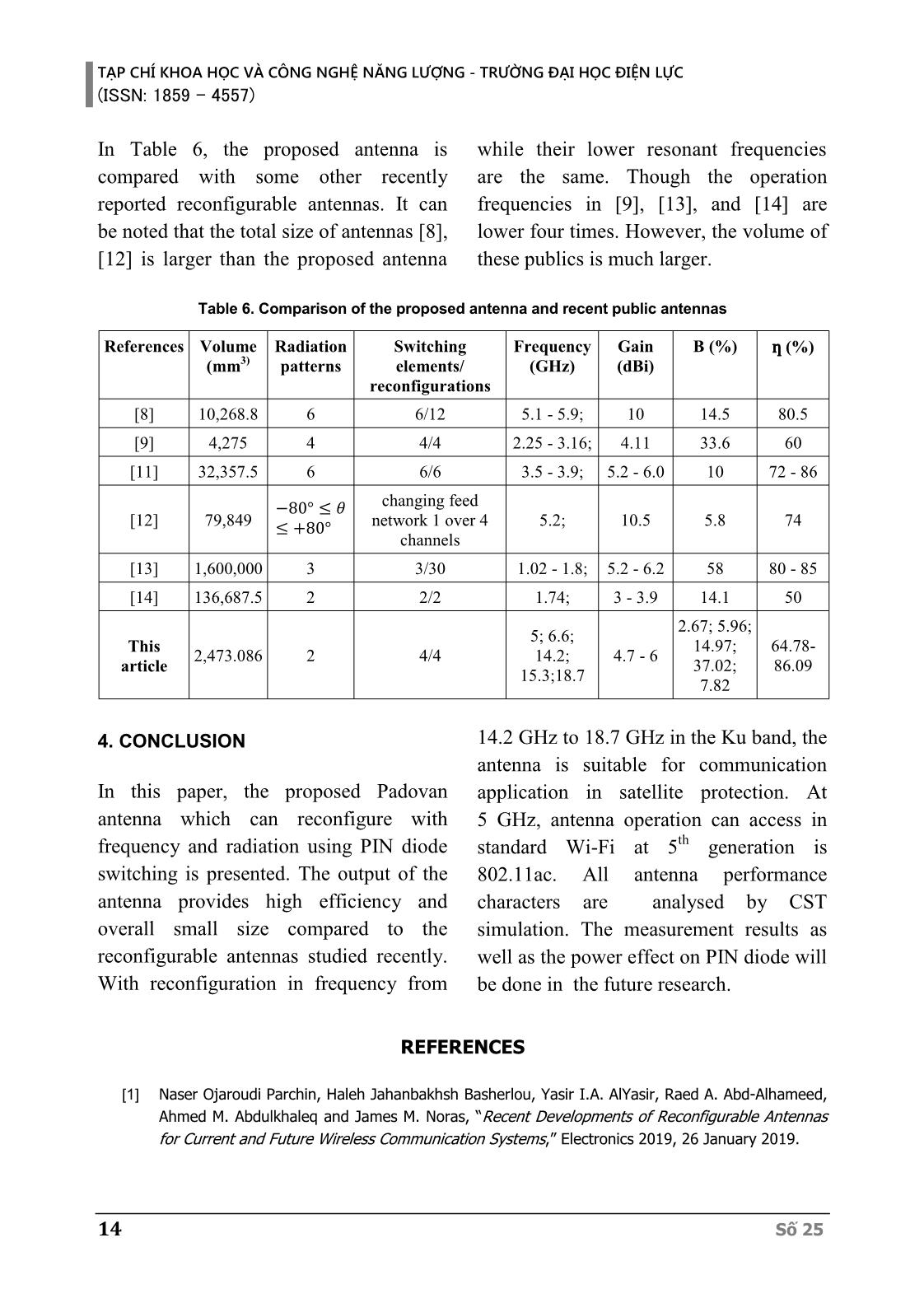
 The antenna operates at 14.2 GHz when
 two over four diodes turn ON. Fig 6(a)
 (b) at S3 and S4 states shows the main beam radiation direction
 Fig 4. S11 parameters of frequency between these two states in plan = 90°.
 reconfiguration At 6.7 GHz, the antenna can change its
 direction from +6° to 19° as shown in
 Fig 6(b).
(a) at S1 and S6 states (b) at S3 and S4 states
 Fig 5. Radiation pattern of frequency
 reconfiguration (c) at 14.2 GHz band (b) at 6.7 GHz band
 Fig. 6. The direction pattern of radiation
3.2. Radiation pattern reconfiguration reconfiguration
The proposed antennas are structured for
elemental radiation at different points on
the rectangular platform. Thus, the
directional radiation at the two and three
diodes is activated for different radiations.
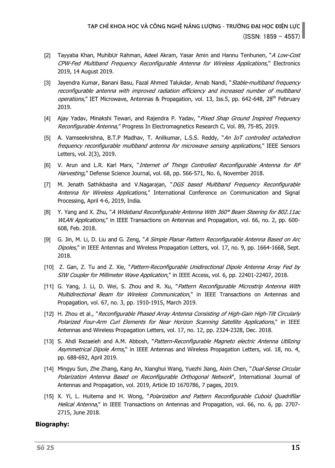
Table 5 and Figure 6 and 7 display the
changing of the radiation antenna by
turning the diodes OFF or ON at different (a) at 14.2 GHz band
positions while maintaining the same
frequency.
 Table 5. The different states of the radiation
 pattern reconfiguration
 Freq. S11 Gain ƞ (%)
 State D (°) B (%)
 (GHz) (dB) (dBi)
 S2 14.24 +52 26.7 20.75 4.8 77.19 (b) at 6.7 GHz band
 Fig. 7. S11 parameters of radiation
 S5 14.2 27 22.8 6.11 6.1 78.44
 reconfiguration
Số 25 13
TẠP CHÍ KHOA HỌC VÀ CÔNG NGHỆ NĂNG LƯỢNG - TRƯỜNG ĐẠI HỌC ĐIỆN LỰC
(ISSN: 1859 - 4557)
In Table 6, the proposed antenna is while their lower resonant frequencies
compared with some other recently are the same. Though the operation
reported reconfigurable antennas. It can frequencies in [9], [13], and [14] are
be noted that the total size of antennas [8], lower four times. However, the volume of
[12] is larger than the proposed antenna these publics is much larger.
 Table 6. Comparison of the proposed antenna and recent public antennas
 References Volume Radiation Switching Frequency Gain B (%) ƞ (%)
 (mm3) patterns elements/ (GHz) (dBi)
 reconfigurations
 [8] 10,268.8 6 6/12 5.1 - 5.9; 10 14.5 80.5
 [9] 4,275 4 4/4 2.25 - 3.16; 4.11 33.6 60
 [11] 32,357.5 6 6/6 3.5 - 3.9; 5.2 - 6.0 10 72 - 86
 −80° ≤ 휃 changing feed
 [12] 79,849 ≤ +80° network 1 over 4 5.2; 10.5 5.8 74
 channels
 [13] 1,600,000 3 3/30 1.02 - 1.8; 5.2 - 6.2 58 80 - 85
 [14] 136,687.5 2 2/2 1.74; 3 - 3.9 14.1 50
 2.67; 5.96;
 5; 6.6;
 This 14.97; 64.78-
 2,473.086 2 4/4 14.2; 4.7 - 6
 article 37.02; 86.09
 15.3;18.7
 7.82
4. CONCLUSION 14.2 GHz to 18.7 GHz in the Ku band, the
 antenna is suitable for communication
In this paper, the proposed Padovan application in satellite protection. At
antenna which can reconfigure with 5 GHz, antenna operation can access in
frequency and radiation using PIN diode standard Wi-Fi at 5th generation is
switching is presented. The output of the 802.11ac. All antenna performance
antenna provides high efficiency and characters are analysed by CST
overall small size compared to the simulation. The measurement results as
reconfigurable antennas studied recently. well as the power effect on PIN diode will
With reconfiguration in frequency from be done in the future research.
 REFERENCES
 [1] Naser Ojaroudi Parchin, Haleh Jahanbakhsh Basherlou, Yasir I.A. AlYasir, Raed A. Abd-Alhameed,
 Ahmed M. Abdulkhaleq and James M. Noras, “Recent Developments of Reconfigurable Antennas
 for Current and Future Wireless Communication Systems,” Electronics 2019, 26 January 2019.
14 Số 25
 TẠP CHÍ KHOA HỌC VÀ CÔNG NGHỆ NĂNG LƯỢNG - TRƯỜNG ĐẠI HỌC ĐIỆN LỰC
 (ISSN: 1859 - 4557)
 [2] Tayyaba Khan, MuhibUr Rahman, Adeel Akram, Yasar Amin and Hannu Tenhunen, “A Low-Cost
 CPW-Fed Multiband Frequency Reconfigurable Antenna for Wireless Applications,” Electronics
 2019, 14 August 2019.
 [3] Jayendra Kumar, Banani Basu, Fazal Ahmed Talukdar, Arnab Nandi, “Stable-multiband frequency
 reconfigurable antenna with improved radiation efficiency and increased number of multiband
 operations,” IET Microwave, Antennas & Propagation, vol. 13, Iss.5, pp. 642-648, 28th February
 2019.
 [4] Ajay Yadav, Minakshi Tewari, and Rajendra P. Yadav, “Pixed Shap Ground Inspired Frequency
 Reconfigurable Antenna,” Progress In Electromagnetics Research C, Vol. 89, 75-85, 2019.
 [5] A. Vamseekrishna, B.T.P Madhav, T. Anilkumar, L.S.S. Reddy, “An IoT controlled octahedron
 frequency reconfigurable multiband antenna for microwave sensing applications,” IEEE Sensors
 Letters, vol. 2(3), 2019.
 [6] V. Arun and L.R. Karl Marx, “Internet of Things Controlled Reconfigurable Antenna for RF
 Harvesting,” Defense Science Journal, vol. 68, pp. 566-571, No. 6, November 2018.
 [7] M. Jenath Sathikbasha and V.Nagarajan, “DGS based Multiband Frequency Reconfigurable
 Antenna for Wireless Applications,” International Conference on Communication and Signal
 Processing, April 4-6, 2019, India.
 [8] Y. Yang and X. Zhu, "A Wideband Reconfigurable Antenna With 360° Beam Steering for 802.11ac
 WLAN Applications," in IEEE Transactions on Antennas and Propagation, vol. 66, no. 2, pp. 600-
 608, Feb. 2018.
 [9] G. Jin, M. Li, D. Liu and G. Zeng, "A Simple Planar Pattern Reconfigurable Antenna Based on Arc
 Dipoles," in IEEE Antennas and Wireless Propagation Letters, vol. 17, no. 9, pp. 1664-1668, Sept.
 2018.
 [10] Z. Gan, Z. Tu and Z. Xie, "Pattern-Reconfigurable Unidirectional Dipole Antenna Array Fed by
 SIW Coupler for Millimeter Wave Application," in IEEE Access, vol. 6, pp. 22401-22407, 2018.
 [11] G. Yang, J. Li, D. Wei, S. Zhou and R. Xu, "Pattern Reconfigurable Microstrip Antenna With
 Multidirectional Beam for Wireless Communication," in IEEE Transactions on Antennas and
 Propagation, vol. 67, no. 3, pp. 1910-1915, March 2019.
 [12] H. Zhou et al., "Reconfigurable Phased Array Antenna Consisting of High-Gain High-Tilt Circularly
 Polarized Four-Arm Curl Elements for Near Horizon Scanning Satellite Applications," in IEEE
 Antennas and Wireless Propagation Letters, vol. 17, no. 12, pp. 2324-2328, Dec. 2018.
 [13] S. Ahdi Rezaeieh and A.M. Abbosh, "Pattern-Reconfigurable Magneto electric Antenna Utilizing
 Asymmetrical Dipole Arms," in IEEE Antennas and Wireless Propagation Letters, vol. 18, no. 4,
 pp. 688-692, April 2019.
 [14] Mingyu Sun, Zhe Zhang, Kang An, Xianghui Wang, Yuezhi Jiang, Aixin Chen, "Dual-Sense Circular
 Polarization Antenna Based on Reconfigurable Orthogonal Network", International Journal of
 Antennas and Propagation, vol. 2019, Article ID 1670786, 7 pages, 2019.
 [15] X. Yi, L. Huitema and H. Wong, "Polarization and Pattern Reconfigurable Cuboid Quadrifilar
 Helical Antenna," in IEEE Transactions on Antennas and Propagation, vol. 66, no. 6, pp. 2707-
 2715, June 2018.
Biography:
Số 25 15
TẠP CHÍ KHOA HỌC VÀ CÔNG NGHỆ NĂNG LƯỢNG - TRƯỜNG ĐẠI HỌC ĐIỆN LỰC
(ISSN: 1859 - 4557)
 Duong Thi Thanh Tu, received B.E, M.E and PhD degrees in Electronics and
 Telecommunications from Hanoi University of Science in 1999 and 2005, and
 2019, respectively. She is current senior lecturer at Faculty of Telecommunications
 1, Posts and Telecommunications Institute of Technology.
 Research interests include antenna design for new generation wireless networks
 as well as the special structure of material such as metamaterial, electromagnetic
 band gap structure.
 Nguyen Tan Dung: His is current student at Faculty of Telecommunications 1,
 Posts and Telecommunications Institute of Technology.
 His current research interest is antenna design for new generation wireless
 networks.
 Hoang Thi Phuong Thao, Received B.E, M.E and PhD degrees in Electronics and
 Telecommunications from Hanoi University of Science in 2004 and 2007, and
 2019, respectively. She is current senior Lecturer at Electronics and
 Telecommunications Faculty, Electric Power University.
 Her current research interests are designing antenna, metamaterial, and
 localization systems.
16 Số 25
 TẠP CHÍ KHOA HỌC VÀ CÔNG NGHỆ NĂNG LƯỢNG - TRƯỜNG ĐẠI HỌC ĐIỆN LỰC
 (ISSN: 1859 - 4557)
Số 25 17
File đính kèm:
 anten_tai_cau_hinh_theo_gian_do_buc_xa_va_tan_so_su_dung_chu.pdf

