A new linear printed vivaldi antenna array with low sidelobe level and high gain for the band 3.5 GHz
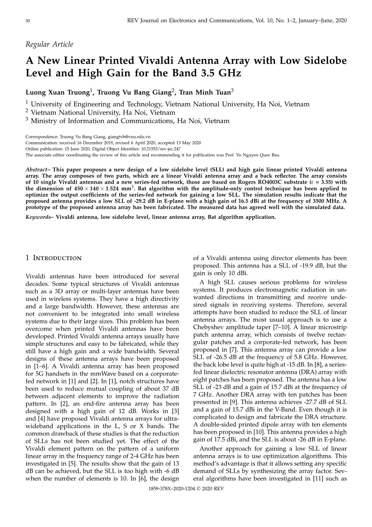
This paper proposes a new design of a low sidelobe level (SLL) and high gain linear printed Vivaldi antenna
array. The array composes of two parts, which are a linear Vivaldi antenna array and a back reflector. The array consists
of 10 single Vivaldi antennas and a new series-fed network, those are based on Rogers RO4003C substrate (# = 3.55) with
the dimension of 450 × 140 × 1.524 mm3. Bat algorithm with the amplitude-only control technique has been applied to
optimize the output coefficients of the series-fed network for gaining a low SLL. The simulation results indicate that the
proposed antenna provides a low SLL of -29.2 dB in E-plane with a high gain of 16.5 dBi at the frequency of 3500 MHz. A
prototype of the proposed antenna array has been fabricated. The measured data has agreed well with the simulated data
Trang 1
Trang 2
Trang 3
Trang 4
Trang 5
Trang 6
Trang 7

Trang 8
Tóm tắt nội dung tài liệu: A new linear printed vivaldi antenna array with low sidelobe level and high gain for the band 3.5 GHz
play adapters ANVIDIA GeForce GT 1030
 -30
 Processors Intel(R) Core(TM)i-8500CPU @3.00GHz (x8)
 RAM 8 GHz -40
 -50
 0
 Normalized Amplitude (dB)
 -60
 Proposed Vivaldi antenna array
 -5
 Uniform antena array
 -70
 -10
 -180 -140 -100 -60 -20 20 60 100 140 180
 Theta (degree)
 -15
 |(dB) Figure 11. Simulation result of radiation pattern with proposed and
 11 uniform weights.
 -20
 |S
 0.25
 -25
 -25
 0.45
 0.5
 -30
 0.55
 -26
 0.75
 -35
 3.2 3.3 3.4 3.5 3.6 3.7 3.8
 -27
 Frequency (GHz)
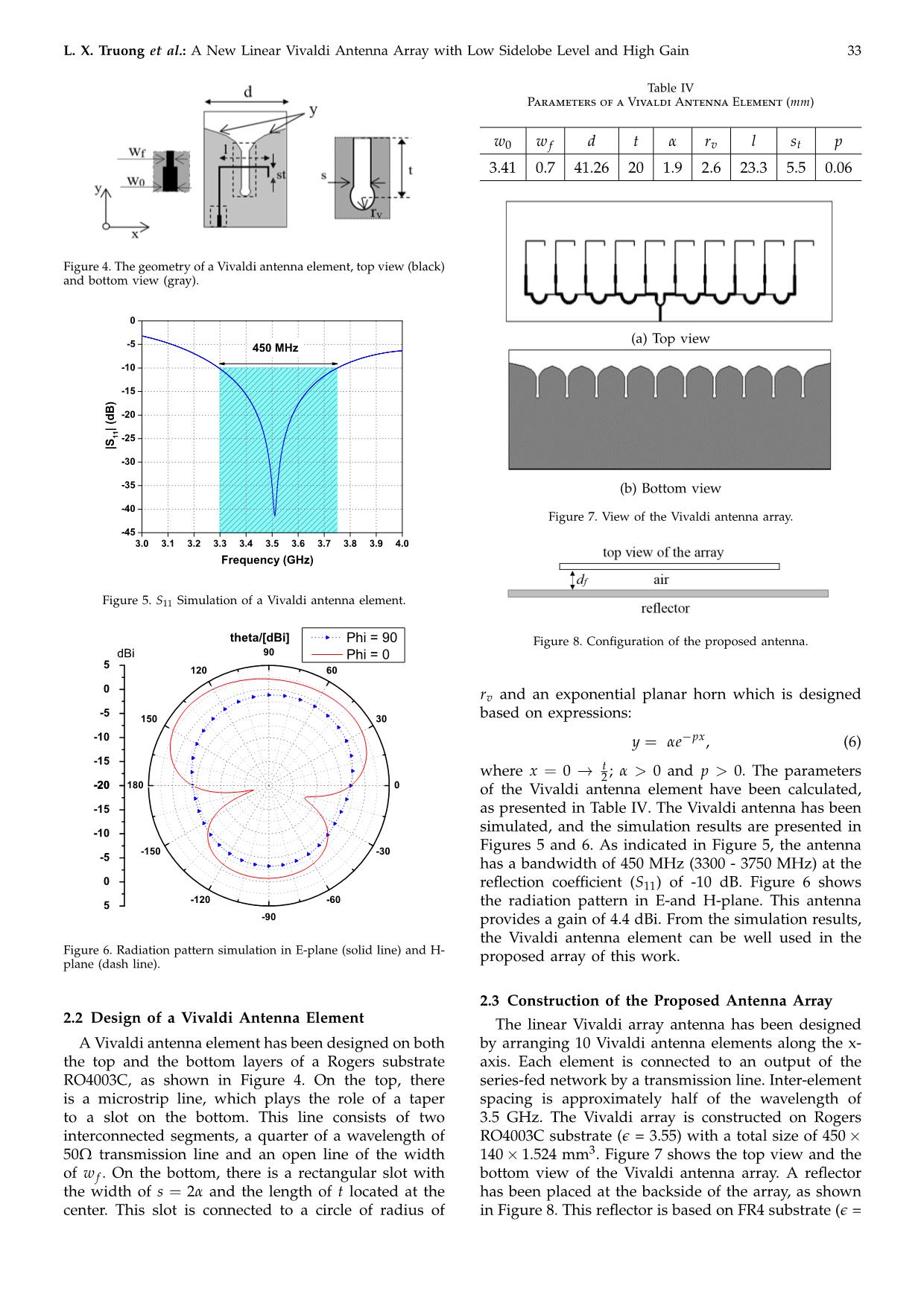
Figure 9. Reflection coefficient simulation with different distances of
the back reflector. SLL (dB) -28
 -5 18.0
 -29
 SLL
 Gain
 -10 16.4
 -30
 3.40 3.42 3.44 3.46 3.48 3.50 3.52 3.54 3.56 3.58 3.60
 Frequency (GHz)
 -15 14.8
 Figure 12. Simulation result of SLL over frequency when d f = 0.5λ.
 SLL (dB)
 -20 13.2
 Gain (dBi)
 -25 11.6 the reflector has also been investigated. Figures 9 and 10
 show the variation of the bandwidth, maximum gain
 -30 10.0 and SLL when d f is changed. The maximum bandwidth
 0.0 0.1 0.2 0.3 0.4 0.5 0.6 0.7 0.8 0.9 1.0 can be achieved at the frequency of 3500 MHz while the
 d /
 f distance is about 0.5λ. As presented in Figure 10, the
 distance df can be determined equal to 0.5λ in terms
Figure 10. SLL and gain simulation with different distances of the of having both a low SLL (-29.2 dB) and the highest
back reflector.
 gain (16.5 dBi). The simulation result of the radiation
 pattern with d f = 0.5λ has been presented in Figures 11
4.4) with the overall dimensions of 503 × 192 × 1.6 mm3. and 12. As presented in Figure 11, the maximum SLL
The back reflector plays a role as a mirror reflecting of the array with the proposed amplitude excitation
the electromagnetic wave according to the image the- weights is 11.5 dB better than that one with uniform
ory [21]. With the presence of the reflector, the elec- excitation weights. Figure 12 shows that the SLL over
tromagnetic wave has been removed from the bottom the frequency range of 3400-3600 MHz always is better
side of this array and has been forwarded to above the than -26 dB, the maximum SLL suppression has been
top side. Thus the maximum gain can be improved. achieved by more than 29 dB in the frequency range of
 d
However, the gain and the radiation direction depend 3490-3550 MHz. Thus, the distance f has been finally
 chosen equal to 0.5λ in this design.
on the distance d f . In this work, all simulations have
been done by using CST Microwave Suite 2018 with
the computer configuration as presented in Table V. 3 Experimental Results
The Vivaldi antenna array has been simulated and op-
timized its elements and feeding-network parameters. A prototype of the proposed Vivaldi array antenna has
The influence of the distance from the antenna array to been fabricated and measured. Figure 13 shows the
L. X. Truong et al.: A New Linear Vivaldi Antenna Array with Low Sidelobe Level and High Gain 35
 0
 3450 MHz
 3500 MHz
 -10
 3520 MHz
 3550 MHz
 3590 MHz
 -20
 -30
 Figure 13. Fabricated Vivaldi antenna array.
 -40
 -4
 -50
 Simulation
 -6 Amplitude (dB) Normalized
 Measurement
 -60
 -8
 -180 -150 -120 -90 -60 -30 0 30 60 90 120 150 180
 Theta (Degree)
 -10
 | (dB)
 -12
 11 Figure 15. Measurement results of the radiation pattern in E-plane at
 |S different frequencies.
 -14
 Table VI
 -16
 The Maximum Measured SLL (dB)
 -18
 Frequency (MHz) 3450 3500 3520 3550 3590
 -20
 3.40 3.45 3.50 3.55 3.60 SLL (dB) -24.5 -27 -26.5 -25.5 -25
 Frequency (GHz)
 Table VII
 Comparison with Other Works
Figure 14. Simulation and measurement results of reflection coeffi-
cients.
 References [16] [10] [8] This work
 Element No. 10 10 8 10
fabricated antenna. Frequency (MHz) 9000 5500 7300 3500
 SLL (dB) -25.3 -26.0 -23.0 -27.0
 The reflection coefficient (S11) has been measured by
using the device Anritsu BTS Master 8222A. Radiation Cross-polarization (dB) -25 -20 -30 -20
patterns have been measured in the far-field region by Maximum gain (dBi) 14.5 17.5 15.7 16.5
using a test antenna chamber, which has the size of 26 Substrate RO4350 RT/5870 RT/5880 RO4003C
× 10 × 10 m3. The measurement has been set with the
frequency step size of 10 MHz and the resolution of
 ◦
the radiation pattern of 1 . The measurement data has The maximum measured SLL is approximately -27.0
been collected and compared to that of the simulated dB, while the simulation result with co-polarization is
one. It is noted that in all figures, the coordinate axes -29.2 dB. On the other hand, neither SLL measurement
(Oz) have been aligned with the maximum direction of nor simulation results is above -20 dB with cross-
the main lobe for the comparison of the simulation and polarization.
measurement results. As indicated in Figure 16, the measurement results
 The measurement and simulation of the reflection still have a slight difference from the simulated ones.
coefficient are presented in Figure 14. The antenna has It may be caused by some reasons. Firstly, SLLs is
the bandwidth of 140 MHz (from 3450 to 3590 MHz) normally very low; thus, it can be changed by inter-
at -10 dB of S11. ference, such as refecting signals from other directions
 The measured radiation patterns at the frequencies of in the measurement process. Secondly, array fabrica-
3450 MHz, 3500 MHz, 3520 MHz, 3550 MHz and 3590 tion may have errors, which is also a factor leading
MHz have been presented in Table VI and Figure 15. to inaccuracy measurement of the radiation pattern.
According to the measurement data, SLLs at those However, the error of -2.2 dB may be an acceptable
frequencies have been suppressed by more than 25 level. For comparison, the measurement data in this
dB. The best SLL suppression has been achieved by work has been compared with that of [8], [10] and [16]
approximately 27.0 dB at the frequency of 3500 MHz. as shown in Table VII. The proposed Vivaldi antenna
 The simulated and measured radiation patterns at array has a SLL of -27.0 dB that is better than SLLs
the frequency of 3500 MHz have been compared in in [8], [10] and [16]. The antenna gain in this work is
detail, as shown in Figure 16. Both co-polarization and about 16.5 dBi that is 1 dB lower than the gain in [10].
cross-polarization data are considered in the E-plane The proposed antenna in this work has better gain and
and H-plane. Obviously, measurement results agree SLL suppression than those in [8] and [16]. The cross-
well with simulation data. The proposed antenna array polarization in this work is equivalent that in [10] and
has the direction of maximum radiation in E-plane. worse than those in [8] and [16].
36 REV Journal on Electronics and Communications, Vol. 10, No. 1–2, January–June, 2020
 [3] X. Li, Z. Zhang, K. Xu, Y. Li, L. Sang, and K. Dai, “Design
 Simulated cross-pol
 -5 of structural-reliable x-band high-gain vivaldi array an-
 Simulated co-pol tenna,” in Proceedings of the 12th International Symposium
 Measured cross-pol
 -27.0 dB
 Measured co-pol on Antennas, Propagation and EM Theory (ISAPE). IEEE,
 -15
 2018, pp. 1–4.
 29.2 dB [4] Y. Yue, Y. Dong, and J. Zhou, “An ultra-wideband vivaldi
 -25 antenna array in l and s bands,” in Proceedings of the
 5th Asia-Pacific Conference on Antennas and Propagation
 -35 (APCAP). IEEE, 2016, pp. 301–302.
 [5] Nurhayati, E. Setijadi, and G. Hendrantoro, “Effect of
 -45 vivaldi element pattern on the uniform linear array
 pattern,” in Proceedings of the International Conference
 NormalizedAmplitude (dB) on Communication, Networks and Satellite (COMNETSAT).
 -55 IEEE, 2016, pp. 42–47.
 [6] S. M. Umar, W. R. Khan, S. Ullah, and F. Ahmad,
 -65 “Gain enhancement technique in vivaldi antenna for 5G
 -180 -150 -120 -90 -60 -30 0 30 60 90 120 150 180 communication,” in Proceedings of International Conference
 Theta (Degree)
 on Computing, Mathematics and Engineering Technologies –
 (a) E-plane iCoMET. IEEE, 2019, pp. 1–3.
 [7] S. Koziel and S.Ogurtsov, “Surrogate-assisted desing
 0 of low-sidelobe microstrip linear arrays with corporate
 feeds,” in Proceedings of MTT-S International Conference on
 Numerical Electromagnetic and Multiphysics Modeling and
 -10
 Optimization (NEMO). IEEE, 2018, pp. 1–3.
 [8] J. Lin, W. Shen, and K.Yang, “A low side lobe and wide
 -20 band series fed linear dielectric resonator antenna array,”
 IEEE Antennas and Wireless Propagation Letters, vol. 16, pp.
 -30 513–516, 2016.
 [9] W. Shen, J. Lin, and K. Yang, “Design of a v-band low
 sidelobe and wideband linear DRA array,” in Proceedings
 -40 of the Progress in Electromagnetic Reseach Symposium, 2016,
 pp. 477–480.
 Simulated cross-pol
 -50 [10] T. T. Toan, T. V. B. Giang, and N. M. Tran, “A novel
 Simulated co-pol
 Normalized Amplitude (dB) Measured cross-pol chebyshev series fed linear array with high gain and low
 Measured co-pol sidelobe level for WLAN outdoor systems,” The Applied
 -60
 -180 -150 -120 -90 -60 -30 0 30 60 90 120 150 180 Computational Electromagnetics Society Journal, vol. 34, pp.
 1143–1151, 2019.
 Theta (Degree)
 [11] J. Kaur and S. Goyal, “A comparative study on linear
 (b) H-plane array antenna pattern synthesis using evolutionary al-
 gorithms,” International Journal of Advanced Research in
Figure 16. The Radiation simulation and measurement results at the Computer Science, vol. 8, pp. 1582–1587, 2017.
frequency of 3500 MHz. [12] Q. Yao and Y. Lu, “Efficient beamforming using bat
 algorithm,” in Proceedings of the IEEE MTT-S International
 Conference on Numerical Electromagnetic and Multiphysics
4 Conclusions Modeling and Optimization (NEMO), 2016.
 [13] T. V. Luyen and T. V. B. Giang, “Interference suppression
 of ULA antennas by phase-only control using bat algo-
A new linear printed Vivaldi antenna array has been rithm,” IEEE Antennas And Wireless Propagation Letters,
developed. The BA has been used to optimize the vol. 16, pp. 3038–3042, 2017.
output amplitude distribution of the series-fed network [14] ——, “Bat algorithm based beam former for interference
of this array. Simulation results show that the SLL suppression by controlling the complex weight,” REV
has been suppressed to -29.2 dB, and the bandwidth Journal on Electronics and Communications, vol. 7, pp. 87–
 93, 2017.
is 140 MHz in the frequency of 3500 MHz with the [15] ——, “Null-steering beam former using bat algorithm,”
reflection coefficient of -10 dB, while the maximum The Applied Computational Electromagnetics Society Journal,
gain can be achieved at 16.5 dBi. A prototype of this vol. 33, pp. 23–29, 2018.
antenna has been fabricated and measured to verify [16] G. Yin, Q. Wu, C. Yu, H. Wang, and W. Hong, “Low
simulation results. The measured data has agreed well sidelobe-level series-fed microstrip antenna array of un-
 equal inter-element spacing,” IEEE Antennas and Wireless
with simulated ones. Propagation Letters, vol. 16, pp. 1695–1698, 2017.
 [17] A. Reyna and L. I. Balderas, “4D antenna array of UWB
 vivaldi elements with low side lobes and harmonic sup-
References presion,” in Proceedings of the IEEE International Sympo-
 sium on Antennas and Propagation & USNC/URSI National
 [1] S. Zhu, H. Liu, P. Wen, and Z. Chen., “A compact gain- Radio Science Meeting. IEEE, 2018, pp. 1505–1506.
 enhanced vivaldi antenna array with suppressed mutual [18] Radio Regulations, International Telecommunication
 coupling for 5G mmwave application,” IEEE Antennas Union, Geneva, 2016.
 and Wireless Propagation Letters, vol. 17, pp. 776–779, 2018. [19] Terrestrial wireless communications: Identifying, managing
 [2] N. Ojaroudiparchin, M. Shen, and G. Pedersen, “Design and harmonizing radio-frequency spectrum, ITU-R News
 of vivaldi antenna array with end-fire beam steering Magazine, Geneva, 2019.
 function for 5G mobile terminals,” in Proceedings of the [20] D. M. Pozar, “Chapter 3: Transmission lines and waveg-
 23rd Telecommunications Forum Telfor (TELFOR). IEEE, uides,” in Microwave Engineering, 4th ed. New York:
 2016, pp. 587–590. John Wiley & Sons, Inc, 2011.
L. X. Truong et al.: A New Linear Vivaldi Antenna Array with Low Sidelobe Level and High Gain 37
[21] C. A. Balanis, “Chapter 15: Reflector antennas,” in An- Truong Vu Bang Giang received the BS and
 tenna Theory Analysis and Design, 3rd ed. New York: MS degree from the VNU-University of Sci-
 John Wiley & Sons, Inc, 2011. ences, in 1994 and 1997, respectively, and the
 Dr.-Ing. (Ph.D.) degree in Electrical Engineer-
 ing from the Hamburg-Harburg University of
 Technology, Hamburg, Germany, in collabo-
 ration with the Institute of Communications
 Luong Xuan Truong received the BS and MS and Navigation, German Aerospace Center,
 degree from the VNU-University of Engineer- in 2006. He is now the Executive Deputy Di-
 ing and Technology in 2009 and 2011, respec- rector of Science and Technology Department
 tively. He is now a Ph.D. student at VNU of Vietnam National University, Hanoi, and
 University of Engineering and Technology. He as the Secretary of the National Research Program for Sustainable
 now works at The Authority of frequency Development of North-West Region of Vietnam. He is currently the
 management of Vietnam as a researcher in Deputy Editor in Chief of Journal of Science, Vietnam National
 the field of frequency spectrum policy and University, Hanoi, Member of IEEE MTTs, and APS. He has served
 planning, primarily, the spectrum for IMT sys- as the Steering Committee (Co-Chair), Organizing Committee (Chair
 tems. and Co-Chairs) or Technical Committee of ATC, REV-ECIT, VJMW,
 His current research interests include RF VJISAP conferences in Vietnam; Scientific and Technical Committee,
techniques for spectrum sharing between IMT and other wireless International Transaction Journal of Engineering, Management, Ap-
systems, microstrip antennas for Mobile and active antenna systems. plied Sciences and Technologies (ITJEMAST).
 His current research interests include Microstrip Antennas for
 Mobile and Handheld Devices; Analysis and Design of conformal
 Antennas; Digital Beamforming and Beamsteering for Smart Anten-
 nas.
 Tran Minh Tuan received the BE degree and
 ME degree in Satellite Communications from
 Moscow Institute of Technology in Russia
 in 1994 and 1995, respectively. In 2004, he
 received a Ph.D. degree in electronics and
 telecommunications at Hanoi University of
 Technology, Vietnam. From 2012, he is the
 Associate Professor in the VNU University of
 Engineering and Technology, Hanoi National
 University. Now he is Vice President of Na-
 tional Institute of Information and Communi-
 cations Strategy, MIC of Vietnam.
 His current research interests include master plans, strategies,
 policies in the fields of telecommunications, ICT, Cyber Security, In-
 ternet media and digital economy development, and radio/television
 broadcasting/propagation.
File đính kèm:
 a_new_linear_printed_vivaldi_antenna_array_with_low_sidelobe.pdf

