Nuclear Science and Technology - Volume 9, Number 4, December 2019
Abstract: Grid spacers installed in subchannels of fuel assemblies for nuclear reactors can promote
heat transfer. However, the fluid velocity and bubble behavior are greatly affected as the crosssectional area of the flow passage changes. Therefore, the void fraction distribution behind the
obstacle that simulates the grid spacer shape simply was measured by using a wire mesh sensor
(WMS) system. Moreover, a two-phase flow analysis was performed to investigate the effect of the
obstacle on the bubble behavior in a vertical duct.
Keywords: Bubbler, Two-phase flow, Obstacle, Vertical duct, WMS, Experiment, Analysis.
I. INTRODUCTION
Clarifying two-phase characteristics
in a nuclear reactor core is important in
particular to enhance the thermo-fluid safety
of nuclear reactors. Moreover, correct data
on bubbly flow in subchannels with spacers
are needed in order to verify two-phase flow
models in conventional nuclear safety
analysis codes and validate predicted data
by current CFD codes like a direct twophase flow analysis code (Douce, et al.,
2010). Spacers installed in subchannels of
fuel assemblies have the role of keeping the
interval between adjacent fuel rods constant.
Similarly, in case of PWR the spacer has
also the role as the turbulence promoter.
When the transient event occurs in a nuclear
reactor, two-phase flow is generated by
boiling of water due to heating of fuel rods.
Therefore, it is important to confirm the
bubbly flow behavior around the spacer.
The purpose of this study is to make the
effect of the spacer affecting the bubbly
flow clear and obtain code validation data.
So bubble dynamics around the simply
simulated spacer was visually observed and
the void fraction and interfacial velocity
distributions just behind the simulated
spacer was measured.
II. EXPERIMENTAL METHOD
1. Experimental Apparatus
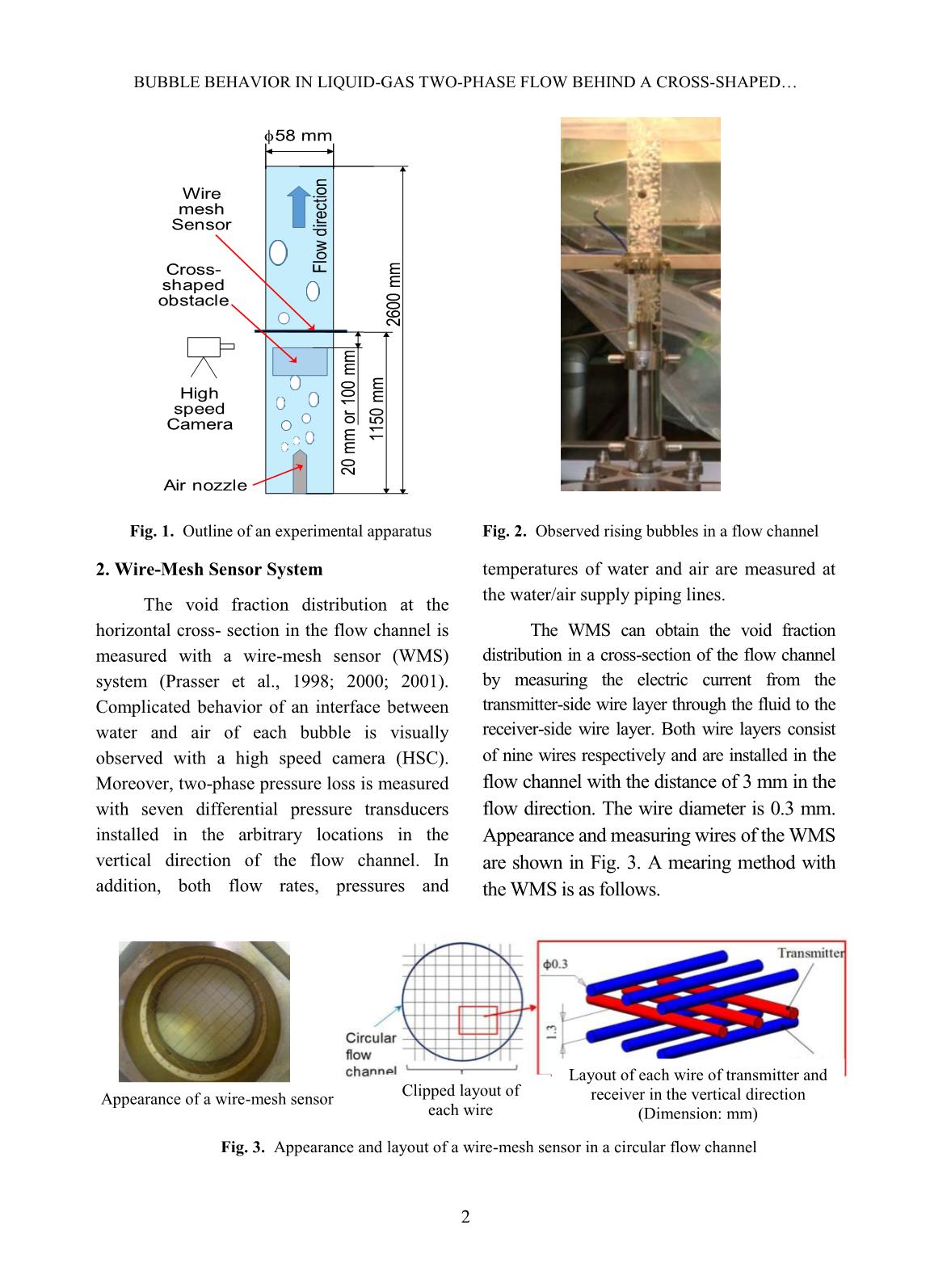
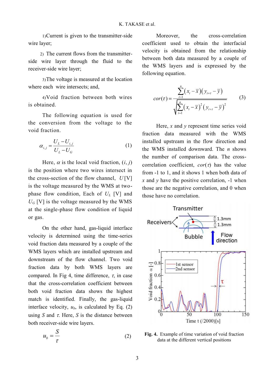
The experimental apparatus mainly
consists of a measuring section and
water/air supply lines and is shown in Fig.
1. The measuring section includes a vertical
flow channel with a diameter of 58 mm
made of an acrylic resin, inlet and outlet
plenums, and an air injection nozzle with
120 injection holes with a diameter of 0.6
mm. Water flows through the inlet plenum
into the flow channel and goes up through
the measuring section to the outlet plenum.
Air is supplied from the air injection nozzle
into the flow channel. As a result, water is
mixed with air and then a water-air twophase flow is formed as can be seen in Fig.
2. Bubbly flow conditions are determined
by both flow rates of water and air.
Trang 1
Trang 2
Trang 3
Trang 4
Trang 5
Trang 6
Trang 7
Trang 8
Trang 9
Trang 10
Tải về để xem bản đầy đủ
Tóm tắt nội dung tài liệu: Nuclear Science and Technology - Volume 9, Number 4, December 2019
e
ionization chamber (Razor chamber). The
output correction factor [
 ]
is
a
DO DUC CHI et al.
51
obtained from the tabulated output correction
factors with respect to the machine specific
reference field as below:
[
 ]
[
 ]
[
 ]
 (4)
III. RESULTS and DISCUSSION
A. Output factors of collimation systems
using TRS398 CoP
Using the conventional formula from
TRS398 CoP, we got the result as Table I.
Table I. Output factors of collimation systems using TRS398 CoP and Razor chamber.
Cone (mm) 4 5 7.5 10 12.5 15 17.5 100 (square)
6X 0.420 0.523 0.662 0.746 0.797 0.834 0.859 1
6XFFF 0.473 0.574 0.702 0.772 0.816 0.846 0.866 1
MLC FS (mm) 0.5 1 2 3 4 5 7 10
6X 0.529 0.754 0.861 0.895 0.921 0.940 0.968 1
6XFFF 0.560 0.782 0.876 0.909 0.932 0.948 0.975 1
Jaw FS (mm) 0.5 1 2 3 4 5 7 10
6X 0.345 0.704 0.850 0.888 0.914 0.936 0.967 1
6XFFF 0.377 0.736 0.867 0.906 0.929 0.947 0.974 1
B. Output factor of collimation systems
using TRS483 CoP:
Intermediate field ( ) of 4 × 4
cm
2
 was selected for calculation of jaw-
shaped fields and MLC-shaped fields. For
cone, intermediate field was 17.5 mm
conical field because we need to
normalize these data to that of 10 × 10
cm
2
 field size. The results were obtained
as Table II.
Table II. Output factor of collimation systems using TRS483 CoP (Razor chamber and Razor diode)
Cone (mm) 4 5 7.5 10 12.5 15 17.5 100 (square)
Square Equi. Field
size (cm) 0.708 0.885 1.327 1.77 2.212 2.655 3.097 10
6X 0.522 0.599 0.713 0.773 0.814 0.841 0.864 1
6XFFF 0.578 0.648 0.745 0.797 0.830 0.856 0.871 1
MLC Field size(mm) 0.5 1 2 3 4 5 7 10
6X 0.608 0.774 0.871 0.905 0.927 0.945 0.971 1
6XFFF 0.643 0.792 0.881 0.918 0.938 0.954 0.978 1
Jaw Field size(mm) 0.5 1 2 3 4 5 7 10
6X 0.619 0.756 0.84 0.876 0.901 0.924 0.961 1
6XFFF 0.652 0.771 0.846 0.884 0.907 0.928 0.963 1
C. Comparison of results between TRS483
and TRS398 CoP:
Based on these results, the difference
between ROF curves is significant between the
two different methods (CoPs) for MLC-shaped
field size and for jaw-shaped field size less than
3 × 3 cm for both the 6X and 6XFFF beams.
The smallest difference was observed
with MLC-shaped fields while the biggest
difference was observed with cone-shaped
RELATIVE OUTPUT FACTORS OF DIFFERENT COLLIMATION SYSTEMS IN TRUEBEAM
52
fields as seen in Fig.3 and Fig.4. At 0.5 × 0.5
cm
2
 squared field and 4 mm conical field, the
output factor difference of 6X and 6XFFF
beams were -44.2%/-42.2%, -13.0%/-13.0%, -
19.6%/-18.2% for jaw-shaped, MLC-shaped
and cone-shaped fields, respectively. TRS398
CoP gave underestimation of a relative output
factor in comparison with TRS483 CoP. The
large difference was always seen at field sizes
smaller than 4 × 4 cm
2
.
Fig. 3. Difference of TRS398 and TRS483 CoP in relative output factor of MLC and Jaws collimations.
Fig. 4. Difference of TRS398 and TRS483 CoP in relative output factor of cone collimations.
0.3
0.4
0.5
0.6
0.7
0.8
0.9
1
0 2 4 6 8 10
R
O
F
Jaw Field Size (cm x cm)
6X Jaw Output Factors
TRS483
TRS398
0.3
0.4
0.5
0.6
0.7
0.8
0.9
1
0 2 4 6 8 10
R
O
F
Jaw Field Size (cm x cm)
6XFFF Jaw Output Factors
TRS483
TRS398
0.5
0.6
0.7
0.8
0.9
1
0 2 4 6 8 10
R
O
F
MLC Field Size (cm x cm)
6X MLC Output Factors
Razor Chamber -
TRS398
0.5
0.6
0.7
0.8
0.9
1
0 2 4 6 8 10
R
O
F
MLC Field Size (cm x cm)
6XFFF MLC Output Factors
Razor Chamber -
TRS398
TRS483
0.4
0.5
0.6
0.7
0.8
0.9
1
0 10 20 30 40 50 60 70 80 90 100
R
O
F
Coned Field Size (mm)
6X Cone Output Factors
TRS483
TRS398
0.4
0.5
0.6
0.7
0.8
0.9
1
0 10 20 30 40 50 60 70 80 90 100
R
O
F
Coned Field Size (mm)
6XFFF Cone Output Factors
TRS483
TRS398
DO DUC CHI et al.
53
Noticingly, the Razor chamber’s
reading differences between 10 × 10 cm
2
MLC-shaped field and 10 × 10 cm
2
 jaw-
shaped field were just 0.61% and 0.25% for
6X and 6XFFF, respectively. Therefore, these
relative output factors could be used for direct
comparison between jaw-shaped field and
MLC-shaped field of “the same” nominal
field size.
D. Comparison of results between 6X,
6XFFF (TRS483 CoP):
For the same collimation system, output
factor comparisons were also made for 6X and
6XFFF beams after applying TRS483 CoP
(Fig. 5). The biggest differences in output
factor were seen at 0.5 × 0.5 cm
2
 jaw-shaped
field, 0.5 × 0.5 cm
2
 MLC-shaped field and
4mm cone-shaped field with values of 5.3%,
5.8% and 10.5%, respectively.
Fig. 5. Difference in output factor of 6X and 6XFFF beams in each collimation system.
E. Comparison of Output Factor curves
between different collimation systems
(TRS483 CoP):
The relative output factor comparisons
were made between MLC, jaws and Cone
systems for both 6X and 6XFFF beams.
Conical collimators are independent
from MLC and Jaws systems. The conical
collimation system has smallest relative
output factor in comparison with that of MLC
and Jaws systems for both 6X and 6XFFF
beams as Fig. 6.
For field sizes bigger than 1 × 1 cm
2
, jaw
system has lower relative output factor than
MLC’s but it is inverse for field size less than 1
× 1 cm
2
.
In a multi-centre analytical study of
small field output factor calculations in
radiotherapy reported by Krzysztof Chełmiński
and Wojciech Bulski, for 2 × 2 cm
2
 MLC-
shaped fields of Varian linacs, the differences
between the treatment planning system output
factors (based on collected beam data) often
exceeded 5% and were below 10% [11]. In
our study, these differences were -1.1% (6X)
and -0.5% (6XFFF) for MLC-shaped fields,
1.3% (6X) and 2.6% (6XFFF) for jaw-shaped
fields, -7.0% (6X) and -5.7% (6XFFF) for
cone-shaped fields. The smaller differences
0.5
0.6
0.7
0.8
0.9
1
0 2 4 6 8 10
R
O
F
Jaw Field Size (cm)
TRS483 Jaws ROF
6X
6XFFF
0.5
0.6
0.7
0.8
0.9
1
0 2 4 6 8 10
R
O
F
MLC Field Size (cm)
TRS483 MLC ROF
6X
6XFFF
0.5
0.6
0.7
0.8
0.9
1
2.5 5 7.5 10 12.5 15 17.5
R
O
F
Coned Field Size (mm)
TRS483 Cone ROF
6X
6XFFF
RELATIVE OUTPUT FACTORS OF DIFFERENT COLLIMATION SYSTEMS IN TRUEBEAM
54
observed in our study for MLC-shaped field
may came from our small field detector, the
Razor chamber.
A multinational audit of small field
output factors calculated by treatment
planning systems used in radiotherapy, the
ROF for small fields calculated by TPSs
were generally larger than measured
reference data. On a national level, 30% and
31% of the calculated ROF of the 2 × 2 cm
2
field exceeded the action limit of 3% for
nominal beam energies of 6 MV and for
nominal beam energies higher than 6 MV,
respectively [12].
The discrepancy above may come
from accuracy of treatment planning
algorithms on measured output factors,
especially for small fields.
Fig. 6. Difference in output factor of difference collimation system for 6X and 6XFFF beams.
CONCLUSIONS
An international code of practice for the
dosimetry of small static fields used in external
beam radiotherapy (TRS483 CoP) was
successfully applied to recalculate relative
output factors for cone system with correction.
Relative output factors for jaw collimation
system were extensively obtained for field size
less than 3 × 3 cm
2
 for Eclipse v.13.6 for 6X
and 6XFFF beams using TRS483 CoP.
Relative output factors were also measured for
MLC collimation system to be compared with
that of the jaw collimation system. The
discrepancy of output factor between jaw-
shaped fields and MLC-shaped fields suggests
that jaw-based beam data itself may not
suitable for MLC-based treatment planning.
Additional measurement of small beam
percentage depth dose and profiles as well as
specific modelling of photon beam for MLC
system may be required.
REFERENCES
[1]. P. Andreo, “The physics of small megavoltage
photon beam dosimetry,” Radiother. Oncol.,
vol. 126, no. 2, pp. 205–213, 2018.
[2]. International Atomic Energy Agency, TRS483,
“An International Code of Practice for
Reference and Relative Dose Determination”,
November, 2017.
0.5
0.55
0.6
0.65
0.7
0.75
0.8
0.85
0.9
0.95
1
0 2 4 6 8 10
R
O
F
Field Size (cm, square equivalent)
6X TRS483 Output Factors
MLC
Jaws
Cone
0.5
0.55
0.6
0.65
0.7
0.75
0.8
0.85
0.9
0.95
1
0 2 4 6 8 10
R
O
F
Field Size (cm, square equivalent)
6XFFF TRS483 Output Factors
MLC
Jaws
Cone
DO DUC CHI et al.
55
[3]. I. J. Das, G. X. Ding, and A. Ahnesjö, “Small
fields: Nonequilibrium radiation dosimetry,”
Med. Phys., vol. 35, no. 1, pp. 206–215, 2008.
[4]. I. J. Das, J. Morales, and P. Francescon, “Small
field dosimetry: What have we learnt?,” in AIP
Conference Proceedings, 2016.
[5]. K. Park, J. Bak, S. Park, W. Choi, and S. W.
Park, “Determination of small-field correction
factors for cylindrical ionization chambers
using a semiempirical method,” Phys. Med.
Biol., vol. 61, no. 3, 2016.
[6]. H. Bouchard, J. Seuntjens, S. Duane, Y. Kamio,
and H. Palmans, “Detector dose response in
megavoltage small photon beams. I. Theoretical
concepts,” Med. Phys., vol. 42, no. 10, 2015.
[7]. E. Mainegra-Hing and B. R. Muir, “On the
impact of ICRU report 90 recommendations on
kQ factors for high-energy photon beams,” Med.
Phys., vol. 45, no. 8, pp. 3904–3908, 2018.
[8]. H. Benmakhlouf, J. Sempau, and P. Andreo,
“Output correction factors for nine small field
detectors in 6 MV radiation therapy photon
beams: A PENELOPE monte carlo study,”
Med. Phys., vol. 41, no. 4, 2014.
[9]. I. J. Das, M. B. Downes, A. Kassaee, and Z.
Tochner, “Choice of Radiation Detector in
Dosimetry of Stereotactic Radiosurgery-
Radiotherapy,” J. Radiosurgery, vol. 3, no. 4,
pp. 177–186, 2000.
[10]. M. Constantin, H. Hsu, S. Mansfield, and M.
Svatos, “Mitigation Strategies to Reduce the
Relative Extrafocal Dose ( RED ),” vol. 33, p.
2525, 2006.
[11]. K. Chełmiński and W. Bulski, “A multi-centre
analytical study of small field output factor
calculations in radiotherapy,” Phys. Imaging
Radiat. Oncol., vol. 6, no. September 2017, pp.
1–4, 2018.
[12]. W. Lechner et al., “A multinational audit of
small field output factors calculated by
treatment planning systems used in
radiotherapy,” Phys. Imaging Radiat.
Oncol., vol. 5, no. September 2017, pp. 58–
63, 2018.
[13]. Aspradakis, M. M. (2009). Small Field MV
Photon Dosimetry. World Congress on
Medical Physics and Biomedical Engineering,
September 7 - 12, 2009, Munich, Germany,
854–854.
[14]. Absorbed Dose Determination in External
Beam Radiotherapy: An International Code of
Practice for Dosimetry based on Standards of
Absorbed Dose to Water. Technical Reports
Series No. 398, International Atomic Energy
Agency, Vienna, 2000.
INSTRUCTIONS FOR AUTHORS
GENERAL INFORMATION
Nuclear Science and Technology (NST), an
international journal of the Vietnam Atomic
Energy Society (VAES) and Vietnam Atomic
Energy Institute (VINATOM), quarterly publishes
articles related to theory and application of nuclear
science and technology. All papers and technical
notes will be refereed.
It is understood that the paper has been neither
published nor currently submitted for publication
elsewhere. The copyright of all published papers
and notes will be transferred in VAES.
DETAILED FIELDS
NST coves all fields of nuclear science and
technology for peaceful utilization of nuclear
energy and radiation. Authors should choose one
of the following fields at the time they submit
their manuscript: 1) Nuclear Physics, 2) Nuclear
Data, 3) Reactor Physics, 4) Thermal Hydraulics,
5) Nuclear Safety, 6) Nuclear I&C, 7) Nuclear
Fuel and Materials, 8) Radioactive Waste
Management, 9) Radiation Protection, 10)
Radiation Technology, 11) Nuclear Techniques in
Food and Agriculture, 12) Nuclear Medicine and
Radiotherapy, 13) Nuclear Techniques in
Industries, 14) Environment Radioactivity, 15)
Isotope Hydrology, 16) Nuclear Analytical
Methods, 17) Health Physics, 18) Fusion and
Laser Technology.
MANUSCRIPT SUBMISSION
Manuscript for publication should be submitted to
the Editorial Office in triplicate by postal mail.
For electronical submission use
nuscitech@vinatom.gov.vn.
Submission Address
Department of Planning, R&D Management
Vietnam Atomic Energy Institute, 59 Ly Thuong
Kiet Street, Hanoi, Vietnam
E-mail: nuscitech@vinatom.gov.vn.
MANUSCRIPT PREPARATION
Manuscripts must be written in English with
adequate margins and indented paragraph. All
manuscript must use SI (metric) units in text,
figures, and tables. Manuscripts should in general
be organized in the following order: title, names of
authors and their complete affiliation including zip
code, abstract (not exceeding 200 words),
keywords (up to 7), introduction, main body of a
paper, acknowledgments, references, appendices,
table & figure captions, tables and figures.
Unnecessary sections may be omitted.
Headings: Use I, II, for major headings and A,
B,  for secondary headings.
Mathematical formulas: All mathematical
formulas should be clearly written, with special
consideration to distinctive legibility of sub-and
superscripts. Equation (at least the principal ones)
should be numbered consecutively using Arabic
numerals in parentheses in the right hand margin.
Tables and Figures: Tables should be numbered
with Roman numerals. Figures should be
numbered consecutively with Arabic numerals in
order of their first appearance and have a complete
descriptive title. They should be typed on separate
sheets. Tables should no repeat data which are
available elsewhere in the paper. Figures should
be original ink drawing or computer drawn figures
in the original and of high quality, ready for direct
reproduction. Figures should be referred to in the
text as, for example, Fig. 1., or Fig. 2. .
Reference: References should be listed at the end
of the text and presented as follows:
[1] C. Y. Fu et al., Nuclear Data for Science and
Technology, S. M. Qaim (Ed.), p. 587 (1991).
[2] C. Kalbach, Z. Phys, A283, 401 (1977).
[3] S. Shibata, M. Imamura, T. Miyachi and M.
Mutou, “Photonuclear spallation reactions in
Cu”, Phys. Rev. C 35, 254 (1987).
KHOA HỌC VÀ CÔNG NGHỆ HẠT NHÂN
Chịu trách nhiệm xuất bản
TRẦN HỮU PHÁT
Chịu trách nhiệm nội dung
TRẦN HỮU PHÁT
TRẦN CHÍ THÀNH
Trình bày
LÊ THÚY MAI
In 200 cuốn, khổ 19x26,5cm tại Công ty TNHH Trần Công
Địa chỉ: số 12 ngách 155/176 Đường Trường Chinh, Hà Nội
Giấy đăng ký kế hoạch xuất bản số: 770/GP-BTTTT cấp ngày 20 tháng 5 năm 2011
In xong và nộp lưu chiểu Quý I năm 2020
25 000đ
File đính kèm:
 nuclear_science_and_technology_volume_9_number_4_december_20.pdf

