Nuclear Science and Technology - Volume 9, Number 2, June 2019
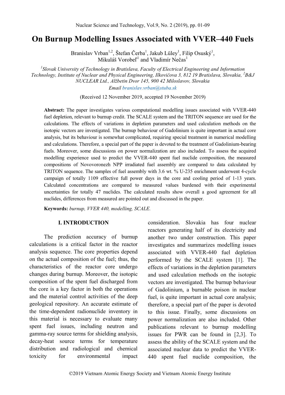
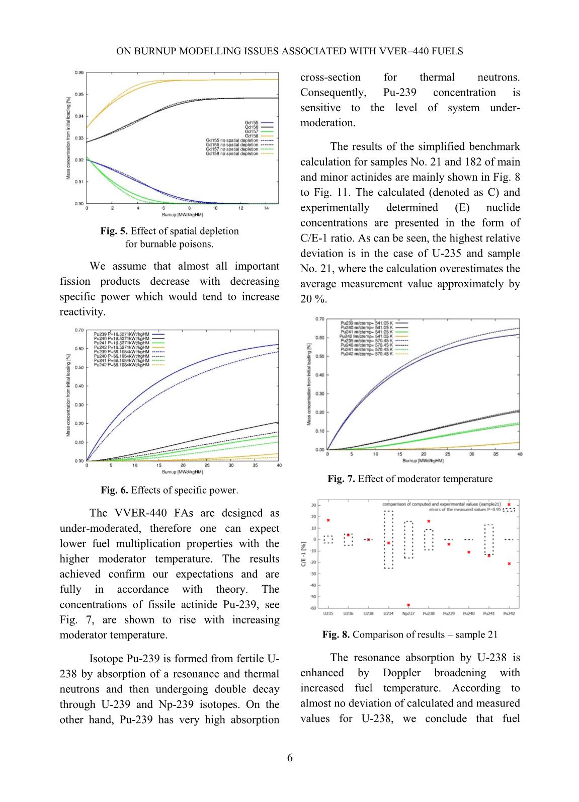
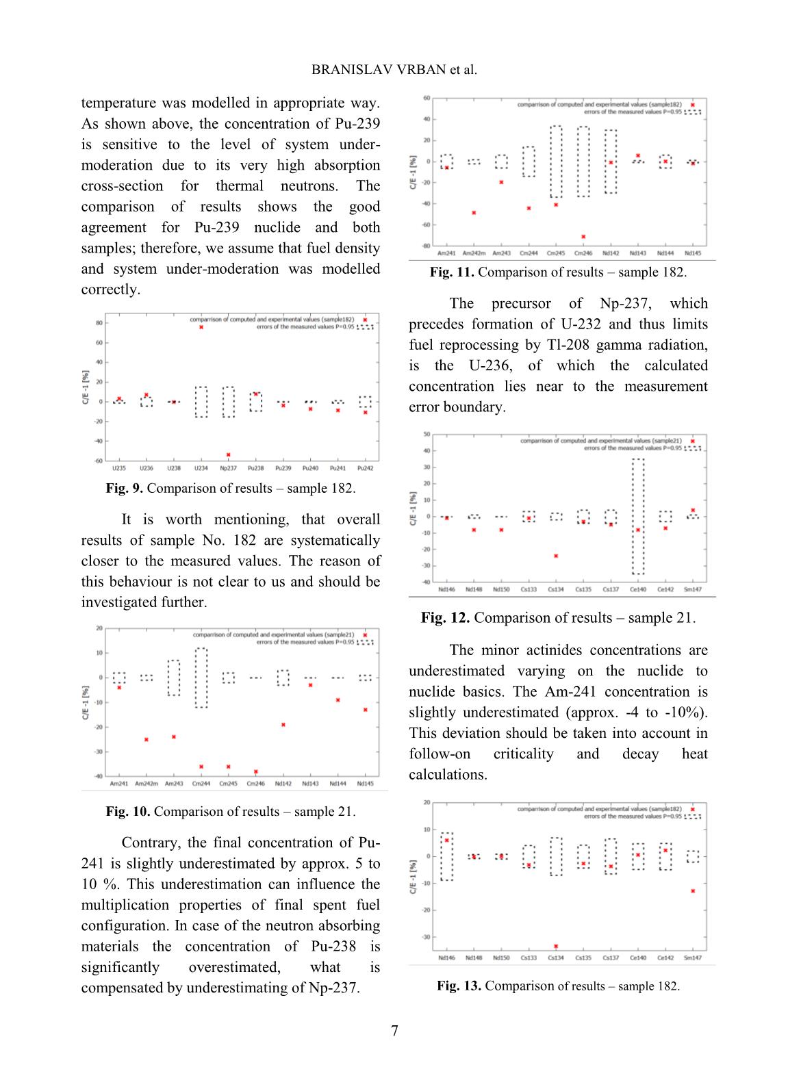
Abstract: The paper investigates various computational modelling issues associated with VVER-440
fuel depletion, relevant to burnup credit. The SCALE system and the TRITON sequence are used for the
calculations. The effects of variations in depletion parameters and used calculation methods on the
isotopic vectors are investigated. The burnup behaviour of Gadolinium is quite important in actual core
analysis, but its behaviour is somewhat complicated, requiring special treatment in numerical modelling
and calculations. Therefore, a special part of the paper is devoted to the treatment of Gadolinium-bearing
fuels. Moreover, some discussions on power normalization are also included. To assess the acquired
modelling experience used to predict the VVER-440 spent fuel nuclide composition, the measured
compositions of Novovoronezh NPP irradiated fuel assembly are compared to data calculated by
TRITON sequence. The samples of fuel assembly with 3.6 wt. % U-235 enrichment underwent 4-cycle
campaign of totally 1109 effective full power days in the core and cooling period of 1-13 years.
Calculated concentrations are compared to measured values burdened with their experimental
uncertainties for totally 47 nuclides. The calculated results show overall a good agreement for all
nuclides, differences from measured are pointed out and discussed in the paper.
Keywords: burnup, VVER 440, modelling, SCALE.
I. INTRODUCTION
The prediction accuracy of burnup
calculations is a critical factor in the reactor
analysis sequence. The core properties depend
on the actual composition of the fuel; thus, the
characteristics of the reactor core undergo
changes during burnup. Moreover, the isotopic
composition of the spent fuel discharged from
the core is a key factor in both the operations
and the material control activities of the deep
geological repository. An accurate estimate of
the time-dependent radionuclide inventory in
this material is necessary to evaluate many
spent fuel issues, including neutron and
gamma-ray source terms for shielding analysis,
decay-heat source terms for temperature
distribution and radiological and chemical
toxicity for environmental impact
consideration. Slovakia has four nuclear
reactors generating half of its electricity and
another two under construction. This paper
investigates and summarizes modelling issues
associated with VVER-440 fuel depletion
performed by the SCALE system [1]. The
effects of variations in the depletion parameters
and used calculation methods on the isotopic
vectors are investigated. The burnup behaviour
of Gadolinium, a burnable poison in nuclear
fuel, is quite important in actual core analysis;
therefore, a special part of the paper is devoted
to this issue. Finally, some discussions on
power normalization are also included. Other
publications relevant to burnup modelling
issues for PWR can be found in [2,3]. To
assess the ability of the SCALE system and the
associated nuclear data to predict the VVER-
measured compositions of Novovoronezh NPP
irradiated fuel assembly are compared to data
calculated by the TRITON sequence in the last
part of the paper. The work done follows the
simplified specification of the computational
benchmark based on the #2670 ISTC project
[4] providing VVER-440 data for 8 samples
cut outs of 4 fuel pins of the fuel assembly
(FA) No. D26135 with the average reached
burnup 38.5 MWd/kgU. The #2670 ISTC
project has was carried out between years 2003
and 2005. Measurements of samples cut out of
were performed in RIAR Dimitrovgrad,
Russia, the final project report is publicly
accessible [6]. The FA irradiation was done
during the 15 - 18 core loads in the fourth
power unit of Novovoronezh NPP.
Trang 1
Trang 2
Trang 3
Trang 4
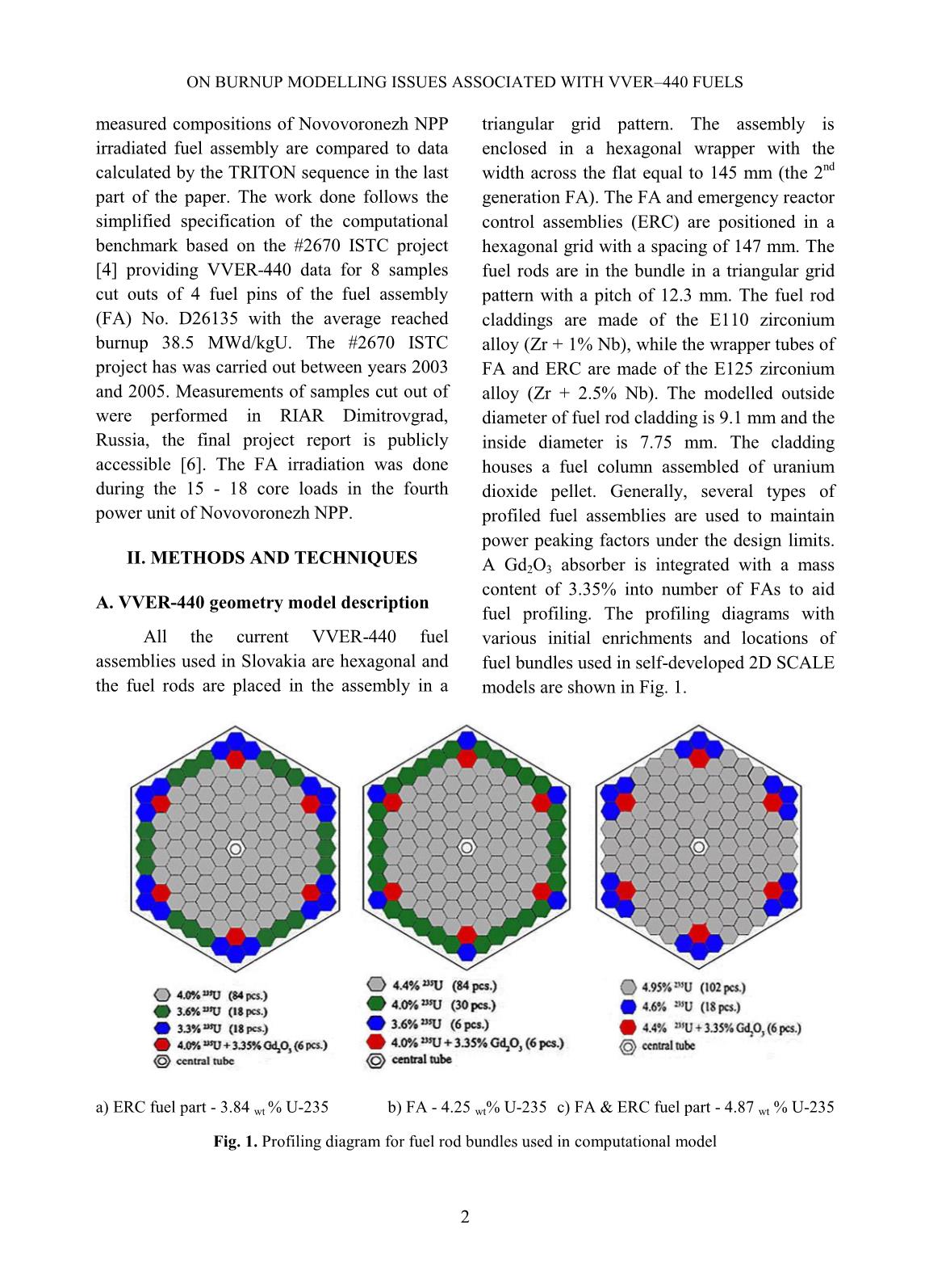
Trang 5
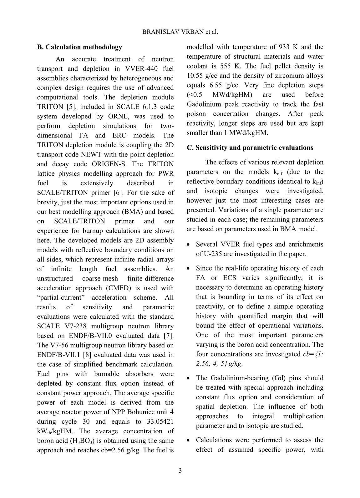
Trang 6
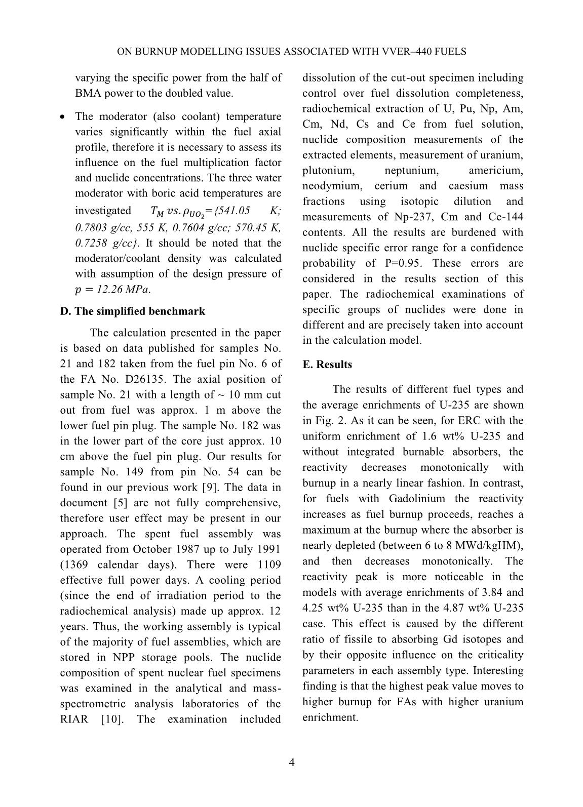
Trang 7
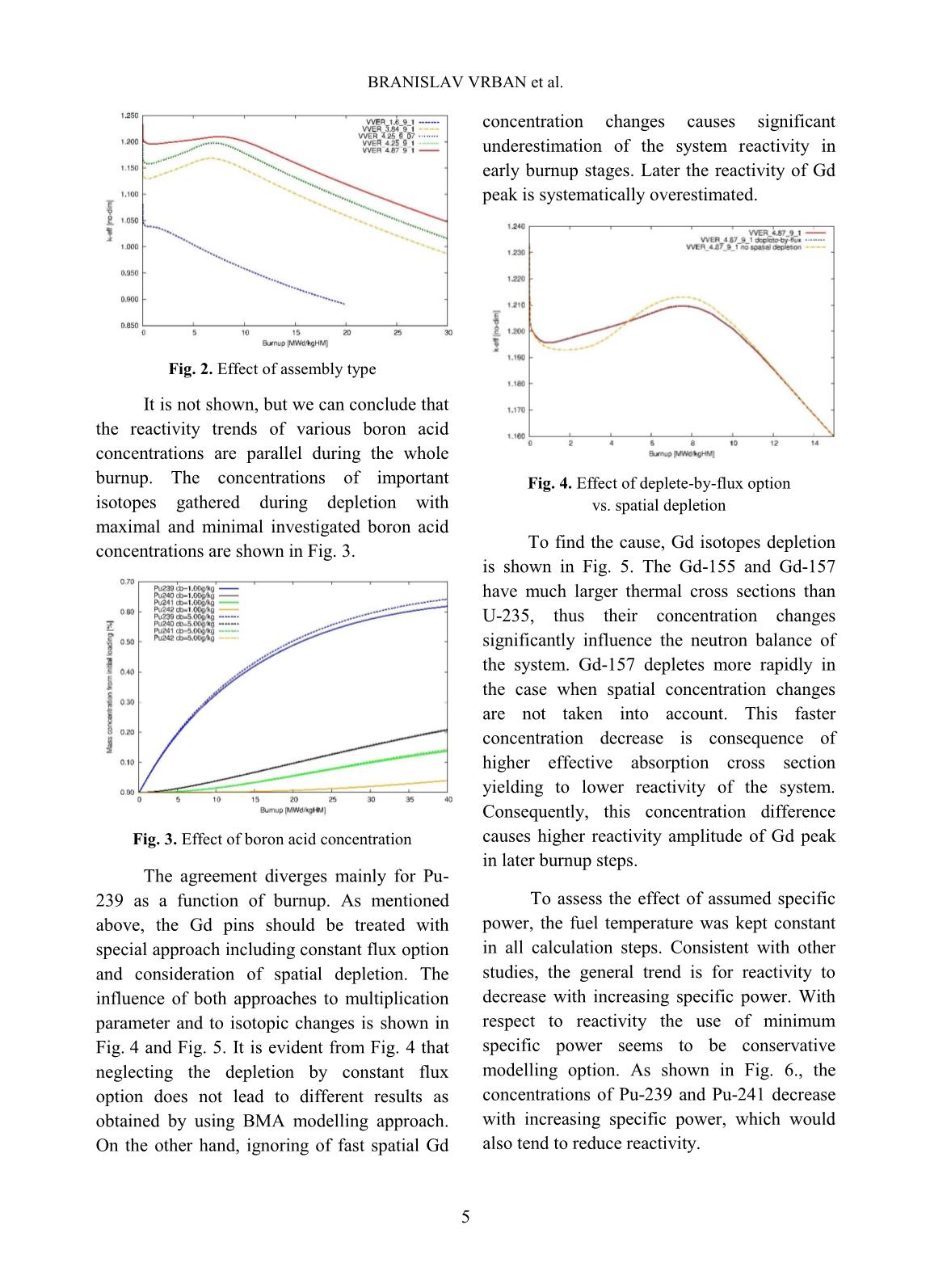
Trang 8
Trang 9
Trang 10
Tải về để xem bản đầy đủ
Tóm tắt nội dung tài liệu: Nuclear Science and Technology - Volume 9, Number 2, June 2019
tem [7].
This paper presents results of applying
Simion program to build some design models
for the system based on design principles of
some built systems in the world and propose a
feasible conceptual design of the system that
can be used to prepare for the stage of detailed
engineering design and construction of the
system in the future.
II. CONTENTS
A. Overview of Simion program
Simion is a software package used
primarily to model electrostatic and magnetic
fields and calculate trajectories of charged
particles in these fields when introducing the
electrode configuration with voltage and initial
conditions of the particles [8]. Simion is
intended to provide direct and highly interactive
methods for simulating a wide variety of general
ion optics problems such as modeling ion source
and detector optics, ion traps, quadrupoles, etc.
Electrostatic and magnetic fields can be
modeled as boundary value problem solutions
of a partial differential equation called the
Laplace equation (or the Poisson equation). The
specific method used within Simion to solve this
equation is an over-relaxation technique, which
is a finite difference method to obtain a best
estimate of potentials for each point within the
fields. After the electrostatic and magnetic fields
have been obtained, a standard fourth-order
Runge-Kutta method is used for numerical
integration of the charged particle trajectory in
three dimensions based on the particle definition
parameters provided by users. In particular,
Simion provides functions of extensive support
in the definition of geometry, data logging, and
visualization. One of the most useful features of
Simion is the capability of using user programs
inside the program. This feature allows users to
directly utilize a variety of programming
languages including Lua, C++, C, PRG, etc. to
flexibly and efficiently extend simulation
capabilities of the program.
B. Methods
According to several reference system
designs, we have successfully built some
simulation models that can be possible designs
for the system by using Simion. Due to
application limitations of the program, the
design models are only used to simulate the
operating principle of slow positron beam
systems rather than specify detailed
engineering designs. Three main individual
simulation models of the slow positron beam
system have been built including:
CAO THANH LONG et al.
47
- The straight-shaped model using the
ExB filter (figure 1).
- The 500 bent-shaped model based on the
design of the SPONSOR system [9, 10] (figure 2).
- The 900 bent-shaped model based on
the design of a slow positron beam system
from Martin Luther University Halle-
Wittenberg, Germany [11] (figure 3).
Fig. 1. The straight-shaped model using ExB filter.
Fig. 2. The 50
0
 bent-shaped model.
Fig. 3. The 90
0
bent-shaped model.
Some positron trajectory calculation tests
have been performed for each model in order to
investigate the influence of design parameters of
each model on the quality of positron beam
obtained on targets, thereby determining which
model was the most reasonable design. The
selected model has been proposed as a feasible
conceptual design for the future system. Tables
of design parameters for the proposed conceptual
design include geometry parameters, electric
parameters and design parameters of coils
creating magnetic fields.
CONCEPTUAL DESIGNING OF A SLOW POSITRON BEAM SYSTEM USING
48
C. Results and Discussions
Case 1: Simulation of the trajectory of a
monoenergetic positron beam
Simion has been used to calculate the
trajectories for 1000 monoenergetic positrons
in a beam emitted isotropically from a circular
uniform distribution source with a radius of 2
mm for each model. The initial kinetic energy
of the beam was 3 eV. The voltages that were
applied to the pre-accelerator and the
accelerator of each model were 27 V and 30
kV, respectively. The simulation results are
shown below in table I, figure 4 and figure 5.
Table I. The simulation results for trajectory of a monoenergetic positron beam
Straight-shaped
model
50
0
 bent-shaped
model
90
0
 bent-shaped
model
Total number of positrons from
source
1000 1000 1000
Total number of positrons
coming to target
789 807 795
The ratio of positron number
coming to target to total positron
number
78.9% 80.7% 79.5%
Beam radius on target 2.75 mm 2.39 mm 2.79 mm
Fig. 4. Spatial distribution of positron beam on the target of the straight-shaped model (left), the 50
0
 bent-
shaped model (middle) and the 90
0
bent-shaped model (right)
Fig. 5. Energy distribution of positron beam on the target of the straight-shaped model (left), the 50
0
 bent-
shaped model (middle) and the 90
0
 bent-shaped model (right)
(FWHM = 5.50 eV) (FWHM = 1.34 eV) (FWHM = 5.71 eV)
CAO THANH LONG et al.
49
From the simulation results, it has been
found that the quality of positron beam
obtained on the targets is influenced by the
model designs. The models with the different
designs do not have completely identical
uniform magnetic fields along their axes,
resulting in different qualities of obtained
positron beam on the targets.
The results of the beam radius of
positron beam on the targets show that
obtained positron beam in case of using the 50
0
bent-shaped model has better convergence
compared to the others. Furthermore, full width
at half maximum (FWHM) of the energy
distribution of positron beam on the target for
the 50
0
 bent-shaped model was smaller than
those of the others. It has shown that the
obtained positron beam of the 50
0
 bent-shaped
model was more mono-energetic than those of
the others.
Case 2: Simulation of the trajectory of a
monoenergetic positron beam in case that a
solenoid deviated from its original position
Another trajectory calculation test has
been done for each model with the same
monoenergetic positron beam in case that the
solenoid surrounding the accelerator of each
model deviated from its original position.
Distributions of positron beam on the target of
each model have been investigated for
comparison. We have simulated two situations
that the solenoid deviations were 1 cm and 2
cm. The simulation results are shown below in
figure 6, figure 7 and figure 8.
Fig.6. Spatial distribution of positron beam on the target of the straight-shaped model in case of solenoid
deviation of 0 cm (left), 1 cm (middle) and 2 cm (right).
Fig.7. Spatial distribution of positron beam on the target of the 50
0
bent-shaped model in case of solenoid
deviation of 0 cm (left), 1 cm (middle) and 2 cm (right).
CONCEPTUAL DESIGNING OF A SLOW POSITRON BEAM SYSTEM USING
50
Fig. 8. Spatial distribution of positron beam on the target of the 90
0
 bent-shaped model in case of solenoid
deviation of 0 cm (left), 1 cm (middle) and 2 cm (right).
The comparison results have shown that
the solenoid deviation influenced the quality of
the positron beam that comes to the targets. For
the straight-shaped model, there were a few
positrons obtained on the target in case of
solenoid deviation of 1 cm. In the case of a
solenoid deviation of 2 cm, we have even got
no positrons coming to the target. For the 90
0
bent-shaped model, the obtained positron
beam has deviated much more from the target
center compared with that of the 50
0
 bent-
shaped model. The beam has even distorted its
shape when increasing the solenoid deviation
to 2 cm. Therefore, we have concluded that
the 50
0
 bent-shaped model in this simulation
case would be the optimal model compared
with the others.
III. CONCLUSIONS
We have come up with the selection of
the 50
0
 bent-shaped model as a conceptual
design for our slow positron beam system
based on simulation test results and
consideration of the design feasibility of the
simulation models. The proposed model can be
a good basis for detailed engineering design
and construction of the system in the future.
The study results have also demonstrated that
Simion program is a very suitable tool for
modeling and simulation of the trajectory of
positron beam flying through electrostatic
fields and magnetic fields of a slow positron
beam system. Research of searching for other
simulation programs to combine with Simion
should be done to further optimize the
conceptual design.
REFERENCES
[1]. P. K. Pujari, K. Sudarshan and D. Dutta (Ed.),
"11th International Workshop on Positron and
Positronium Chemistry (PPC-11)", Journal of
Physics: Conference Series, Volume 618,
Conference 1, 2015.
[2]. P. G. Coleman (Ed.), “Positron Beams and
their applications”, World Scientific,
Singapore, 2000.
[3]. F. A. Selim, A.W. Hunt, J.A. Golovchenko, R.
H. Howell, R. Haakenaasen, K.G. Lynn,
“Improved source and transport of
monoenergetic MeV positrons”, Nuclear
Instruments and Methods in Physics Research
B 171 (2000), 182-188, 2000.
[4]. S. May-Tal Beck, D. Cohen, E. Cohen, A.
Kelleher, O. Hen, J. Dumas, E. Piasetzky, N.
Pilip, G. Ron, I. Sabo-Napadensky, R Weiss-
Babai, “Design of the Slow POsitron faciliTy
(SPOT) in Israel”, 13th International
Workshop on Slow Positron Beam Techniques
and Applications, 2014.
CAO THANH LONG et al.
51
[5]. C. K. Cheung, P. S. Naik, C. D. Beling, S. Fung,
H. M. Weng, “Performance of a slow positron
beam using a hybrid lens design”, Department
of Physics, University of Hong Kong, Pokfulam
Road, Hong Kong, PR China, 2006.
[6]. Xu Hong-Xia, Liu Jian-Dang, Gao Chuan-Bo,
Weng Hui-Min, Ye Bang-Jiao, “SIMION
simulation of a slow pulsed positron beam”,
Department of Modern Physics, University of
Science and Technology of China, Hefei
230026, China, 2012.
[7]. Cao Thanh Long, Nguyen Trung Hieu, Tran
Quoc Dung, Huynh Dong Phuong, “Some
initial results of simulating a positron beam
system by using SIMION”, Nuclear Science
and Technology, Vol.7, No. 3, 17-24, 2017.
[8]. David J. Manura, David A. Dahl, “SIMION
Version 8.0/8.1 User Manual”, Document Revision
5, Scientific Instrument Services Inc., 2011.
[9]. Wolfgang Anwanda, Gerhard Brauer, Maik
Butterling, Hans-Rainer Kissener, Andreas
Wagner, “Design and Construction of a Slow
Positron Beam for Solid and Surface
Investigations”, Defect and Diffusion Forum
Vol. 331, 2012.
[10]. Wolfgang Anwanda, Gerhard Brauer,
Hans-Rainer Kissener, “Magnetically
guided slow positron beam for defect
studies”, Positron Group of TU Dresden at
Research Centre Rossendorf, Dresden,
Germany, 1994.
[11]. R. Krause-Rehberg, “Simple design for a
continuous magnetically guided positron
beam – and – News from the EPOS project”,
Institute of Physics, Martin Luther
University Halle-Wittenberg, Germany,
2010.
INSTRUCTIONS FOR AUTHORS
GENERAL INFORMATION
Nuclear Science and Technology (NST), an
international journal of the Vietnam Atomic
Energy Society (VAES) and Vietnam Atomic
Energy Institute (VINATOM), quarterly publishes
articles related to theory and application of nuclear
science and technology. All papers and technical
notes will be refereed.
It is understood that the paper has been neither
published nor currently submitted for publication
elsewhere. The copyright of all published papers
and notes will be transferred in VAES.
DETAILED FIELDS
NST coves all fields of nuclear science and
technology for peaceful utilization of nuclear
energy and radiation. Authors should choose one
of the following fields at the time they submit
their manuscript: 1) Nuclear Physics, 2) Nuclear
Data, 3) Reactor Physics, 4) Thermal Hydraulics,
5) Nuclear Safety, 6) Nuclear I&C, 7) Nuclear
Fuel and Materials, 8) Radioactive Waste
Management, 9) Radiation Protection, 10)
Radiation Technology, 11) Nuclear Techniques in
Food and Agriculture, 12) Nuclear Medicine and
Radiotherapy, 13) Nuclear Techniques in
Industries, 14) Environment Radioactivity, 15)
Isotope Hydrology, 16) Nuclear Analytical
Methods, 17) Health Physics, 18) Fusion and
Laser Technology.
MANUSCRIPT SUBMISSION
Manuscript for publication should be submitted to
the Editorial Office in triplicate by postal mail.
For electronical submission use
nuscitech@vinatom.gov.vn.
Submission Address
Department of Planning, R&D Management
Vietnam Atomic Energy Institute, 59 Ly Thuong
Kiet Street, Hanoi, Vietnam
E-mail: nuscitech@vinatom.gov.vn.
MANUSCRIPT PREPARATION
Manuscripts must be written in English with
adequate margins and indented paragraph. All
manuscript must use SI (metric) units in text,
figures, and tables. Manuscripts should in general
be organized in the following order: title, names of
authors and their complete affiliation including zip
code, abstract (not exceeding 200 words),
keywords (up to 7), introduction, main body of a
paper, acknowledgments, references, appendices,
table & figure captions, tables and figures.
Unnecessary sections may be omitted.
Headings: Use I, II, for major headings and A,
B,  for secondary headings.
Mathematical formulas: All mathematical
formulas should be clearly written, with special
consideration to distinctive legibility of sub-and
superscripts. Equation (at least the principal ones)
should be numbered consecutively using Arabic
numerals in parentheses in the right hand margin.
Tables and Figures: Tables should be numbered
with Roman numerals. Figures should be
numbered consecutively with Arabic numerals in
order of their first appearance and have a complete
descriptive title. They should be typed on separate
sheets. Tables should no repeat data which are
available elsewhere in the paper. Figures should
be original ink drawing or computer drawn figures
in the original and of high quality, ready for direct
reproduction. Figures should be referred to in the
text as, for example, Fig. 1., or Fig. 2. .
Reference: References should be listed at the end
of the text and presented as follows:
[1] C. Y. Fu et al., Nuclear Data for Science and
Technology, S. M. Qaim (Ed.), p. 587 (1991).
[2] C. Kalbach, Z. Phys, A283, 401 (1977).
[3] S. Shibata, M. Imamura, T. Miyachi and M.
Mutou, “Photonuclear spallation reactions in
Cu”, Phys. Rev. C 35, 254 (1987).
KHOA HỌC VÀ CÔNG NGHỆ HẠT NHÂN
Chịu trách nhiệm xuất bản
TRẦN HỮU PHÁT
Chịu trách nhiệm nội dung
TRẦN HỮU PHÁT
TRẦN CHÍ THÀNH
Trình bày
LÊ THÚY MAI
In 200 cuốn, khổ 19x26,5cm tại Công ty TNHH Trần Công
Địa chỉ: số 12 ngách 155/176 Đường Trường Chinh, Hà Nội
Giấy đăng ký kế hoạch xuất bản số: 770/GP-BTTTT cấp ngày 20 tháng 5 năm 2011
In xong và nộp lưu chiểu Quý IV năm 2019
25 000đ
File đính kèm:
 nuclear_science_and_technology_volume_9_number_2_june_2019.pdf

