Conceptual design of a small-pressurized water reactor using the AP1000 fuel assembly design
This paper presents the conceptual design of a 300 MWt small modular reactor (SMR)
using fuel assemblies of the AP1000 reactor. Numerical calculations have been performed to evaluate
a proper active core size and core loading pattern using the SRAC code system and the JENDL-4.0
data library. The analysis showed that Doppler, moderator temperature, void, and power reactivity
coefficients are all negative over the core lifetime. Semi-analytical thermal hydraulics analysis reveals
acceptable radial and axial fuel element temperature profiles with significant safety margin of fuel and
clad surface temperature. The minimum departure from nucleate boiling ratio (MDNBR) is also
calculated. The results indicate that a cycle length of 2.22 years is achievable while satisfying the
operation and safety-related design criteria with sufficient margins.
Trang 1
Trang 2
Trang 3
Trang 4
Trang 5
Trang 6
Tóm tắt nội dung tài liệu: Conceptual design of a small-pressurized water reactor using the AP1000 fuel assembly design
 Nuclear Science and Technology, Vol.9, No. 2 (2019), pp. 25-30
©2019 Vietnam Atomic Energy Society and Vietnam Atomic Energy Institute
Conceptual design of a small-pressurized water reactor using
the AP1000 fuel assembly design
Van Khanh Hoang
a, *
, Viet Phu Tran
a
, Van Thin Dinh
b
, Hoai Nam Tran
c
a
Institute for Nuclear Science and Technology, VINATOM, 179 Hoang Quoc Viet, Hanoi, Vietnam
b
Faculty of Nuclear Engineering, Electric Power University, 235 Hoang Quoc Viet, Hanoi, Vietnam
c
Institute of Fundamental and Applied Sciences, Duy Tan University, Ho Chi Minh city, Vietnam
*
E-mail: hvkhanh21@gmail.com
(Received 01 November 2019, accepted 13 November 2019)
Abstract: This paper presents the conceptual design of a 300 MWt small modular reactor (SMR)
using fuel assemblies of the AP1000 reactor. Numerical calculations have been performed to evaluate
a proper active core size and core loading pattern using the SRAC code system and the JENDL-4.0
data library. The analysis showed that Doppler, moderator temperature, void, and power reactivity
coefficients are all negative over the core lifetime. Semi-analytical thermal hydraulics analysis reveals
acceptable radial and axial fuel element temperature profiles with significant safety margin of fuel and
clad surface temperature. The minimum departure from nucleate boiling ratio (MDNBR) is also
calculated. The results indicate that a cycle length of 2.22 years is achievable while satisfying the
operation and safety-related design criteria with sufficient margins.
Keywords: small modular reactor, AP1000 reactor, neutronic analysis, thermal hydraulics analysis.
I. INTRODUCTION
In recent years, the small modular
reactors (SMRs), new generation reactors
designed with an electrical output up to 300
MWe, have been received increasing attention
within the nuclear energy community due to a
number of advantages. Because of the small
size, the SMRs require less capital investment
and construction time compared to traditional
commercialized reactors, so that financial risks
could be reduced. The SMR designs can adopt
most of the advanced safety features of the
current technologies. One of the advantages is
that the components of the reactor system can
be fabricated at factories and transported
modularly to the plant site for installation. It is
also more flexible to choose locations for the
SMRs than the traditional reactors, and
therefore, it would be a suitable solution for a
wide range of users and applications, for
instance remote areas with smaller electricity
demand. The SMRs are being developed for a
number of principal reactors including
advanced light water reactors, heavy water
reactors, and the generation IV reactors such as
high temperature gas cooled reactors (HTGRs),
liquid-metal, sodium and gas-cooled fast
reactors (LMFR, SFR, GFR), and molten salt
reactors (MSRs).
About 50 SMR designs are being under
developed world-wide for both electrical
generation and non-electrical application
such as desalination of seawater, district
heating, hydrogen production and other
process heat application. Among those, three
industrial demonstration SMRs are in
construction including CAREM (integral
PWR with the output of 150 – 300 MWe) in
Argentina, HTR-PM (HTGR) in China and
KLT-40S (compact PWR for a floating
nuclear power plant) in Russia. The integral
pressurized water reactor (IPWR) technology
is one of the major near term SMR designs,
of which primary components are contained
CONCEPTUAL DESIGN OF A SMALL-PRESSURIZED WATER REACTOR USING THE AP1000
26
in the reactor vessel. CAREM is an example
of the IPWR technology. CAREM-25, a
prototype reactor with the power of 27 MWe,
is under construction. Other designs of
IPWRs are SMART (Korea), NuScale (US),
mPower (US), Westinghouse SMR (US). The
IPWR of the Westinghouse Electric
Company is based on a partial-height 17x17
fuel assembly used in the AP1000
reactor.
This reactor utilizes passive safety systems
and proven components from the AP1000
plant design. All primary components
including the steam generator and the
pressurizer are located inside the reactor
vessel [3].
In the present work, a conceptual
design of a small PWR core with thermal
output of 300 MWt based on the AP1000
fuel assembly has been presented. Neutronics
analysis has been performed to determine the
core height, the number of fuel assemblies
and core configuration. The neutronic
analysis has been conducted using the SRAC
code system and the JENDL-4.0 library.
Thermal hydraulics analysis has been
conducted to investigate the safety
parameters of the core. Reactivity
coefficients regarding the change in
temperature of fuel, coolant, etc. were also
investigated to ensure the safety feature of
the newly designed SMR core.
II. CODE AND DESIGN PROCEDURE
The SRAC2006 code system [4] and the
JENDL-4.0 nuclear data library [5] were used
for performing the design process of the SMR
core. For the core burnup calculation process is
divided into two steps. Firstly, cell burnup
calculation using the PIJ module was
conducted to produce few-group burnup
dependent homogenized macroscopic cross-
sections. Secondly, the COREBN [6] was used
for three-dimensional core burnup calculation
based on the macroscopic cross-section
interpolation. In order to confirm the core
design criteria, thermal hydraulics analysis for
the hottest channel in the core was performed
to establish adequate heat removal capability of
the design. Analytical models and equations
are utilized for heat conduction within the fuel
element and convection to the coolant [7].
Calculations of the MDNBR have also been
performed for the hottest channel using
empirical correlation and W-3 correlation [8].
The design process consists of two steps as
follows:
a) Estimation of core size: The objective of
this step is to determine the active fuel length
and the number of fuel assemblies. Neutron
transport calculations have been performed
for an infinite core by imposing reflective
boundary condition in the assembly level
model. From the mass of uranium per
assembly, the required number of fuel
assemblies for the core can be determined. In
this determination of core size, a four-year
core lifetime, the average discharge burnup of
40 GWd/t with a single batch refueling
scheme and a capacity factor of 1.0 were
assumed.
b) Determination of core loading pattern:
Once the required number assemblies are
achieved, a symmetrical arrangement of the
fuel assemblies in the active core zone is
proposed for the initial core configuration. The
core loading pattern is developed for the core
design to meet the design criteria. Fuel
assemblies with higher U-235 enrichment are
selected with a high priority, and located in the
peripheral core locations to achieve a uniform
power distribution and maximum fuel
utilization. Finally, the core that meets the
specified performance requirements is selected
for further analysis.
HOANG VAN KHANH et al.
27
Fig. 1. Locations of fuel rods, guide thimbles (GT)
and instrumentation thimble (IT) in a fuel assembly.
III. CORE DESIGN AND
PERFORMANCE ANALYSIS
A. Core parameters
The Robust Fuel Assembly (RFA)
design is used in the AP1000 reactor. The
typical fuel assembly, with 17x17 array,
contain 264 fuel rods, 24 guide thimbles, and
1 instrumentation thimble as shown in Fig. 1
[3]. The SMR core is designed with a
thermal output of 300 MWt. The typical
uranium oxide fuel rods (UO2) with 2.35,
3.40, and 4.95 wt.% U-235 enrichments are
used in the current SMR [9]. The main
design parameters and targets for the SMR
are specified in Table 1. In the AP1000
reactor design, in order to control excess
reactivity and flatten power distribution,
burnable absorber rods and integral fuel
burnable absorbers are also used. In this
study, only fuel assemblies without burnable
absorber are considered to design a new core.
For the control element assemblies (CEAs),
the standard 24 finger Ag-In-Cd (AIC) rod
control cluster assembly is exploited.
B. Estimation of core size
In order to determine the active fuel
length, a three-dimensional infinite core
model was developed based on an assembly
level model with reflective boundary
condition using the SRAC code system. The
model consists of an active fuel zone and two
reflector zones at the top and the bottom. The
AP1000 fuel assembly with the highest U-
235 enrichment, i.e., 4.95 wt.%, was selected
for the active fuel zone. Reflective boundary
condition was assumed for peripheral core,
and extrapolated boundary condition was set
at the top and the bottom. Fig. 2 shows the
evolution of the infinite neutron
multiplication factor (k-inf) at the begin of
cycle (BOC) and the number of assemblies
loaded into the core as functions of the active
fuel length. It can be seen that when the
active fuel length is less than 190 cm, the k-
inf increases rapidly with the increase of the
active fuel length. The k-inf value is nearly
unchanged with the active fuel length greater
than 190 cm. Therefore, the active fuel
length of 190 cm was selected, and the
number of fuel assemblies in the core was
determined as 45 assemblies.
Fig. 2. Variation of infinite multiplication factor
and required number of assemblies with increasing
active fuel length.
CONCEPTUAL DESIGN OF A SMALL-PRESSURIZED WATER REACTOR USING THE AP1000
28
Table I. Main design parameters and conditions (k-eff: effective neutron multiplication factor).
Fig. 3. Core configurations of the SMR (yellow, blue, and green blocks represent fuel assembly assemblies
with 4.95, 3.40 and 2.35 wt.% U-235 enrichment, respectively. White block represents water filled position).
a) Core model 1 b) Core model 2 c) Core model 3
D. Analysis of temperature coefficients and
control element assemblies
In order to investigate the feedbacks due
to changes of fuel and coolant temperatures,
the temperature reactivity coefficients have
been calculated. A change in temperature of
fuel material causes a change of neutron cross-
section, which is so-called the Doppler
broadening effect, resulting in a change in
reactivity. Meanwhile, a change in coolant
HOANG VAN KHANH et al.
29
temperature results in the change of moderator
density, which leads to a change in reactivity
of the core. For safe operation, negative values
of the temperature reactivity coefficients are
desirable. In the numerical analysis, the
temperature of fuel and/or coolant was
increased by 50K. For the isothermal
coefficient, both temperature of fuel and
coolant were increased by 50K.
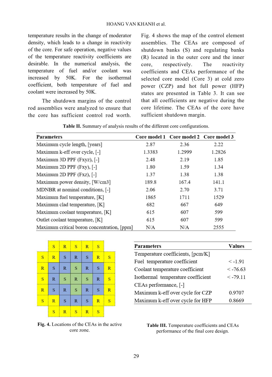
The shutdown margins of the control
rod assemblies were analyzed to ensure that
the core has sufficient control rod worth.
Fig. 4 shows the map of the control element
assemblies. The CEAs are composed of
shutdown banks (S) and regulating banks
(R) located in the outer core and the inner
core, respectively. The reactivity
coefficients and CEAs performance of the
selected core model (Core 3) at cold zero
power (CZP) and hot full power (HFP)
states are presented in Table 3. It can see
that all coefficients are negative during the
core lifetime. The CEAs of the core have
sufficient shutdown margin.
Table II. Summary of analysis results of the different core configurations.
Fig. 4. Locations of the CEAs in the active
core zone.
Table III. Temperature coefficients and CEAs
performance of the final core design.
CONCEPTUAL DESIGN OF A SMALL-PRESSURIZED WATER REACTOR USING THE AP1000
30
IV. CONCLUSIONS
Conceptual design calculation of a 300
MWt SMR based on the fuel assemblies of the
AP1000 reactor has been carried out. The core
consists of 45 fuel assemblies with an active
core height of 190 cm could operate up to 2.22
years without refueling. The Doppler and
moderator temperature coefficients are
negative throughout the core lifetime.
Maximum values of fuel, cladding and coolant
temperatures are within the design limits. The
DNBR remains greater than 3.71 for the active
core region. The analysis results represent that
the final core design satisfies all the design
criteria with significant safety margins.
ACKNOWLEDGEMENTS
This research is funded by Ministry of
Science and Technology (MOST) of Vietnam
under grant number ĐTCB. 02/19/VKHKTHN.
REFERENCES
[1]. International Atomic Energy. “Advances in
Small Modular Reactor Technology
Developments, A Supplement to: IAEA
Advanced Reactors Information System
(ARIS)”, 2018.
[2]. Organisation for Economic Co-operation and
Development, Nuclear Energy Agency. “Current
Status, Technical Feasibility and Economics of
Small Nuclear Reactors”, June 2011.
[3]. Jun Liao, et al.. “Preliminary LOCA Analysis
of the Westinghouse Small Modular Reactor
Using the WCOBRA/TRAC-TF2 Thermal-
Hydraulics Code”, Proceedings of ICAPP'12
Chicago, USA, June 24-28, 2012.
[4]. Keisuke Okumura, Teruhiko Kugo, Kunio
Kaneko and Keichiro Tsuchihashi.
“SRAC2006: A Comprehensive Neutronics
Calculation Code System”, JAEA-Data/Code
2007-004, 2007.
[5]. Keiichi Shibata, et al.. “JENDL-4.0: A New
Library for Nuclear Science and Engineering,
Journal of Nuclear Science and Technology”,
vol. 48, No. 1, p. 1-30, 2011.
[6]. Keisuke Okumura. “COREBN: A Core Burn-
up Calculation Module for SRAC2006”,
JAEA-Data/Code 2007-003, 2007.
[7]. James J. Duderstadt Louis J. Hamilton.
"Nuclear Reactor Analysis", John Wiley &
Sons, Inc., 1976.
[8]. Tong L.S. “Prediction of Departure from
Nucleate Boiling for an Axially Non-Uniform
Heat Flux Distribution”. Journal of Nuclear
Energy, vol. 21, p. 241-248, 1967.
[9]. U.S. Nuclear Regulatory Commission (NRC),
“Westinghouse AP1000 Design Control
Documentation (DCD)”, Rev. 19, Chapter 4,
Westinghouse Electric Company, 2011.
File đính kèm:
 conceptual_design_of_a_small_pressurized_water_reactor_using.pdf

