Blotches detection
Abstract. Blotch detection and removal is an important issue for archive film restoration
and it can be extended in many other field of image processing. In this work, a new
proposal including an automatic detection method and inpainting scheme is introduced.
First, a technique for automatically detecting blotches based on local changes of pixels on
consecutive frames is applied. Specifically, a two-stage Simplified Ranked Order
Difference (SROD) detector is proposed to identify blotches on frames. Next, an improved
inpainting was applied to restore the blotches so that it is undetectable by viewers. Our
proposal is executed automatically without external parameters. The proposal has been
tested on a serial of natural images with different sizes and resolutions. Experimental
results show that the proposed solution has been successfully detected with fairly high
accuracy and quite smooth restored blotches. Based on result analysis, the proposal has
many potential and applications in the future. Index Terms-blotch detection, blotch
removal, restoration, inpainting.
Trang 1
Trang 2
Trang 3
Trang 4
Trang 5
Trang 6
Trang 7
Tóm tắt nội dung tài liệu: Blotches detection
�,��) � �����
∀� ∈ �� ,ĥ (� ) � ���� �
, ,
�� ,� �
and � � . (3)
��−�� ��� ��−�,�� �����
� � � � � � ̌ , ,
���(� ,� )(� ) ������ ,� � ��ĥ(� ,�� ) (� )����� ,� �
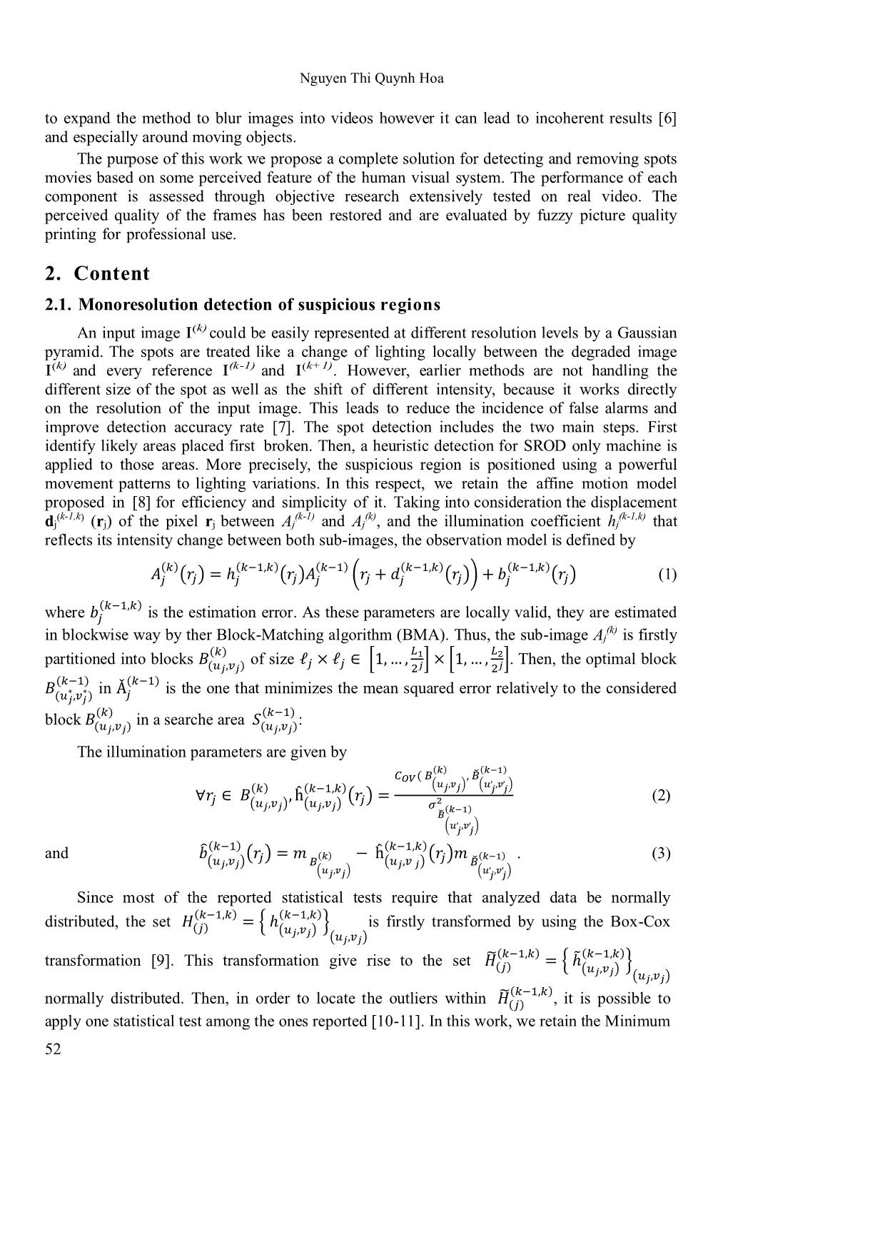
Since most of the reported statistical� � tests require that analyzed� � data be normally
distributed, the set is firstly transformed by using the Box-Cox
��−�,�� ��−�,��
��� (��,��)
transformation [9]. �� This transformation� ��ℎ � give(��,� �) rise to the set
��−�,�� ��−�,��
���� ̃(��,��)
normally distributed. Then, in order to locate the outliers within�� �, � it�ℎ is possible�(��, � to�)
apply one statistical test among the ones reported [10-11]. In this work,� �we−� ,retain�� the Minimum
������
52
Blotches detection
Covariance Determinant (MCD) test for its efficiency and relatively low computational
complexity [10]. The MCD test provides a set of a typical values of the illumination
��−�,��(k) (k-1)
coefficient that are asssociated to candidate blocks in Aj and Aj and are more susceptible to
��� (k)
be blotched. The same procedure is carried out�� to detect suspicious blocks between Aj and
(k+1)
Aj . Only the blocks that are judged as suspicious in both the backward and the forward
(k-1) (k) (k+1) (k)
directions (by considering respectively the pairs (Aj , Aj ) and (Aj , Aj ) are retained for
the final blotch detection step since blotches are considered as illumination variations occuring
in both directions.
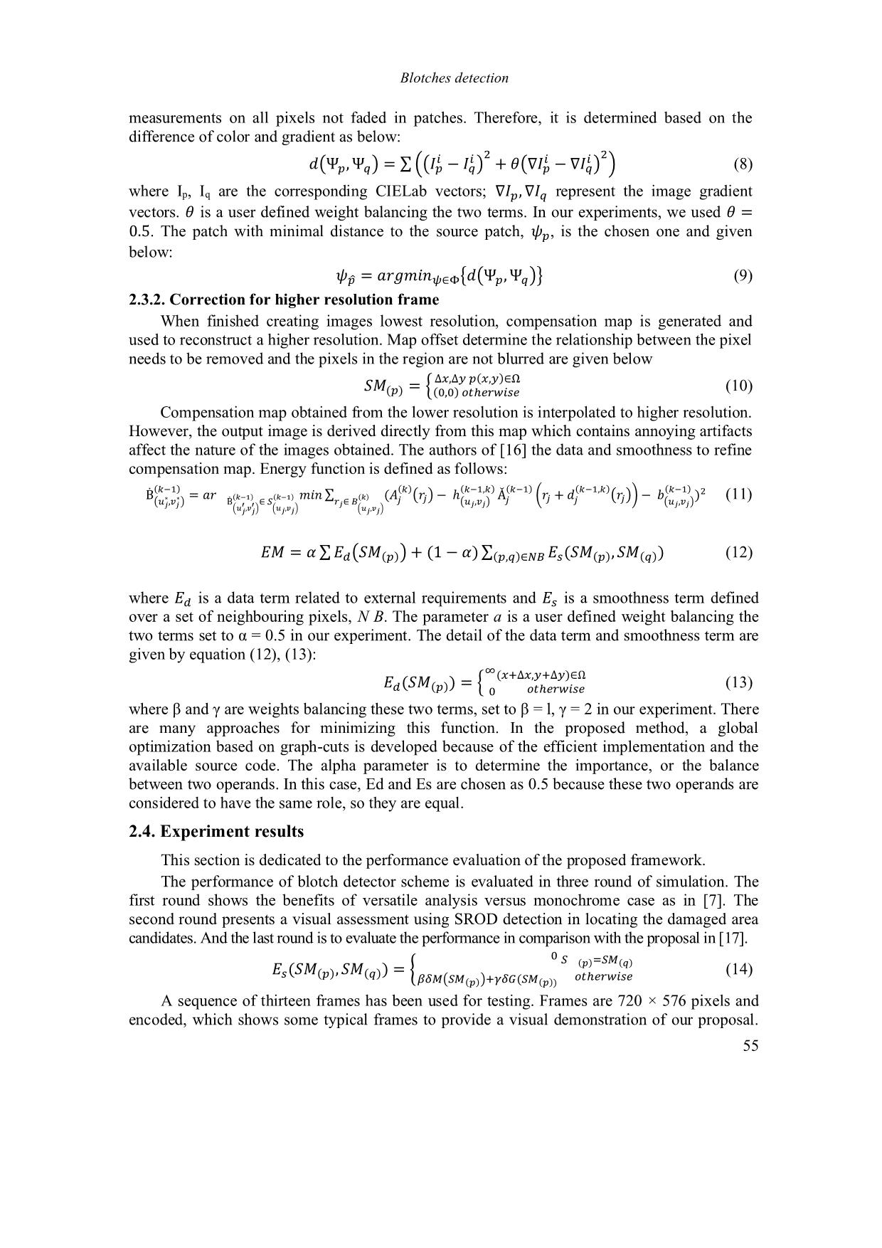
2.2. Blotch detection
Given the positions of the suspicious regions at different resolution levels, it is necessary
to deduce the positions of the retained candidate regions at the initial resolution level. Since
the goal behind resorting to a multiscale analysis is to handle the different sizes of the
blotches, we consider a block at the initial resolution level as suspicious if it has been judged
as such at, at least one resolution level initial resolution level. Since the goal behind resorting
to a multiscale analysis is to handle the different sizes of the blotches, we consider a block at
the initial resolution level as suspicious if it has been judged as such at, at least one resolution
level
The final step consists of detecting the corrupted pixels in each candidate region at the
�,∀1 ≤ � ≤ �.
initial resolution of . For this purpose, one of the reported heuristic detectors as the SDIa,
the ROD, the SROD,��� or the AR based detectors is used between suspicious blocks in and
their homologous in �the motion compensated refrence frames. ���
� �
2.3. Blotch removal
We assume that the spots are identified and detected correctly in the previous step at this
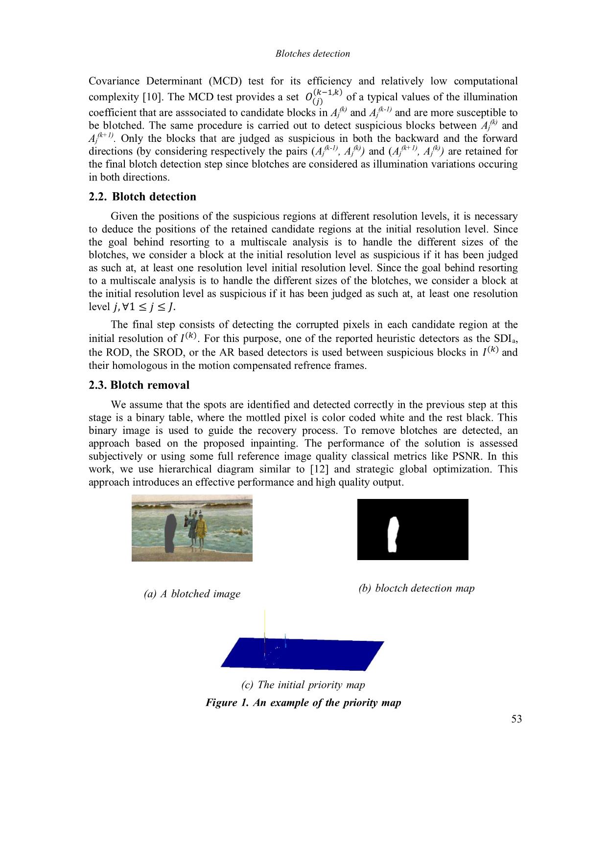
stage is a binary table, where the mottled pixel is color coded white and the rest black. This
binary image is used to guide the recovery process. To remove blotches are detected, an
approach based on the proposed inpainting. The performance of the solution is assessed
subjectively or using some full reference image quality classical metrics like PSNR. In this
work, we use hierarchical diagram similar to [12] and strategic global optimization. This
approach introduces an effective performance and high quality output.
(a) A blotched image (b) bloctch detection map
(c) The initial priority map
Figure 1. An example of the priority map
53
Nguyen Thi Quynh Hoa
Firstly, a Gaussian pyramid was built from the original image to create hierarchical
diagrams of input images. A set of images with different levels of detail can be created with
as the input or original image. Number of pyramid levels depending on the original size
of the image and the minimum resolution allowed. Then, a strategy used to fill in missing areas
with�� �� the lowest resolution, . Athigher resolutions, inpainting problem are modeled as a
graph optimization labels which help to show the selected label for each pixel unknown. It can
be determined by optimizing� � the energy function optimization algorithm by global, multi-
labeled graph cut [13]. A description of the algorithm removes spots is given in Figure 1.
2.3.1. Correction of lowest resolution frame
At lowest resolution, a template-based approach is used to remove the blob by using
priority based on the window and choose the patch. Recommended removal methods work
repeated as follows:
- Detect spots: Identify spots and their boundaries based on the binary image. If no pixels
in the spot, the algorithm is terminated due spots completely erased.
- Define priorities edit: Calculator and randomly select a pixel p with the highest priority
and determines a patch, P, gathered at p. In this work, we used the model of the most common
priorities proposed in [14, 15] Combine the patch: Find a patch is not blurred, , similar to
with mean squared error of pixel squares is not blurred.
�� ��
- Blotch removal: Fill in missing information in patch .
- Information update: Update the binary mask image and return the step 1.
��
Correction priority: So good priorities is essential because it directly affects the quality of
the output. In this work, we used the model of the most common priorities proposed in [15] and
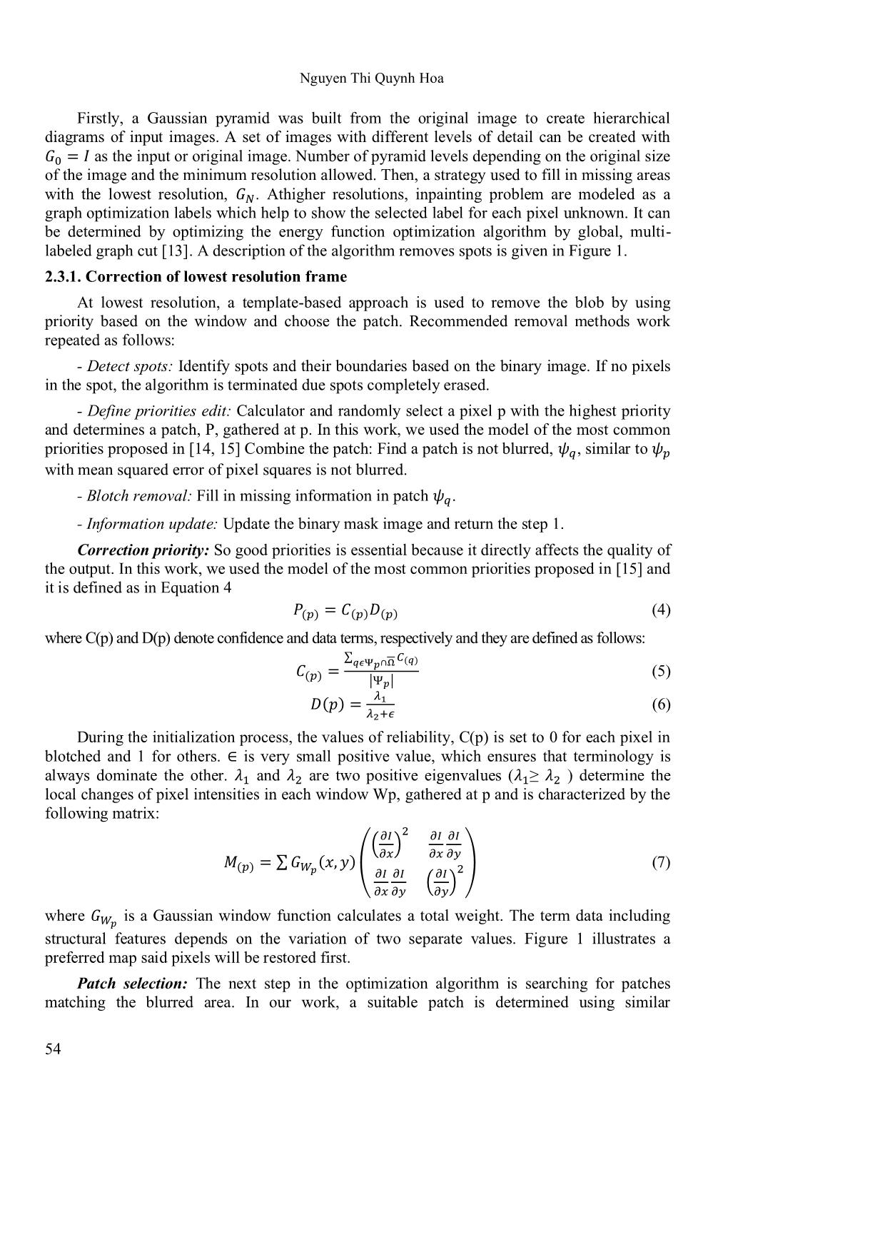
it is defined as in Equation 4
(4)
where C(p) and D(p) denote confidence and data terms, respectively and they are defined as follows:
���� ����������
(5)
∑����∩� ����
���� � |��| (6)
��
During the initialization process, the� values��� � �of�+ reliability,�� C(p) is set to 0 for each pixel in
blotched and 1 for others. is very small positive value, which ensures that terminology is
always dominate the other. and are two positive eigenvalues ( ≥ ) determine the
local changes of pixel intensities∈ in each window Wp, gathered at p and is characterized by the
following matrix: �� �2 �� �2
�� 2 �� �� (7)
���� �� ��
��� ��
� � ∑ � ��, �� � �� �� �� 2��
where is a Gaussian window function calculates�� �� a total��� �weight. The term data including
structural features depends on the variation of two separate values. Figure 1 illustrates a
��
preferred� map said pixels will be restored first.
Patch selection: The next step in the optimization algorithm is searching for patches
matching the blurred area. In our work, a suitable patch is determined using similar
54
Blotches detection
measurements on all pixels not faded in patches. Therefore, it is determined based on the
difference of color and gradient as below:
(8)
2 2
where I , I are the corresponding CIELab vectors;� � � represent� the image gradient
p q �(Ψ�,Ψ�) � ∑ �(�� ���) ��(∇�� � ∇��) ��
vectors. is a user defined weight balancing the two terms. In our experiments, we used
� �
. The patch with minimal distance to the source patch,∇� ,∇ � , is the chosen one and given
below: � � �
�
0.5 � (9)
2.3.2. Correction for higher resolution frame
��̂ � �������∈Φ{�(Ψ�,Ψ�)}�
When finished creating images lowest resolution, compensation map is generated and
used to reconstruct a higher resolution. Map offset determine the relationship between the pixel
needs to be removed and the pixels in the region are not blurred are given below
(10)
Compensation map obtained from the lower∆� ,∆resolution�����,��∈Ω is interpolated to higher resolution.
����� � ���,������������
However, the output image is derived directly from this map which contains annoying artifacts
affect the nature of the images obtained. The authors of [16] the data and smoothness to refine
compensation map. Energy function is defined as follows:
(11)
��−∗ �∗� ����� ����� ��� ��� ��−�,�� ��−�� ��−�,�� ��−�� 2
(��,�� ) �Ḃ ′ ′ ∈�� ��∈�� � � (��,��) � � � � (��,��)
�Ḃ � �� ���,��� ���,������ ∑ ���,����� (� ) ��ℎ Ǎ �� �� (� )���� � �
(12)
�� �� ∑ ��(�����) ��1 ��� ∑��,��∈�� ��������, ������
where is a data term related to external requirements and is a smoothness term defined
over a set of neighbouring pixels, N B. The parameter a is a user defined weight balancing the
two�terms�� �set�to�α�=�0.5�in�our�experiment.�The detail of the data�� term and smoothness term are
given by equation (12), (13):
(13)
∞��+∆�,�+∆��∈Ω
where�β�and�γ�are�weights�balancing�these�two�terms,�set�to�β�=�l,�γ�=�2�in�our�experiment.�There
���������� � � ����������
are many approaches for minimizing this function. In the proposed method, a global
optimization based on graph-cuts is developed because of the efficient implementation and the
available source code. The alpha parameter is to determine the importance, or the balance
between two operands. In this case, Ed and Es are chosen as 0.5 because these two operands are
considered to have the same role, so they are equal.
2.4. Experiment results
This section is dedicated to the performance evaluation of the proposed framework.
The performance of blotch detector scheme is evaluated in three round of simulation. The
first round shows the benefits of versatile analysis versus monochrome case as in [7]. The
second round presents a visual assessment using SROD detection in locating the damaged area
candidates. And the last round is to evaluate the performance in comparison with the proposal in [17].
(14)
��� ���=�����
A sequence of thirteen����� frames���, �� �has���� been���� used(�� for���) +testing.������ �Frames��� ���������� are 720 × 576 pixels and
encoded, which shows some typical frames to provide a visual demonstration of our proposal.
55
Nguyen Thi Quynh Hoa
The first line contains some corrupted frames and the blotch detection is detected and
represented by binary mask frames of the second line. The blotch removal frames are shown in
the last line. In order to evaluate of performance the blotch removal algorithm, we compared
with some state-of-the-art inpainting methods such as A. Criminisi et al. [14], Wu et al. [18] and
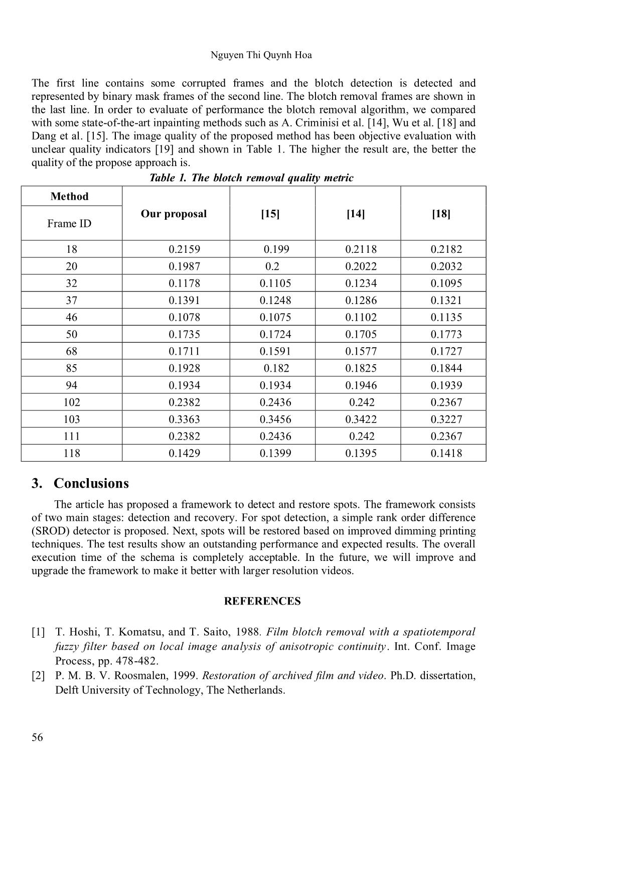
Dang et al. [15]. The image quality of the proposed method has been objective evaluation with
unclear quality indicators [19] and shown in Table 1. The higher the result are, the better the
quality of the propose approach is.
Table 1. The blotch removal quality metric
Method
Our proposal [15] [14] [18]
Frame ID
18 0.2159 0.199 0.2118 0.2182
20 0.1987 0.2 0.2022 0.2032
32 0.1178 0.1105 0.1234 0.1095
37 0.1391 0.1248 0.1286 0.1321
46 0.1078 0.1075 0.1102 0.1135
50 0.1735 0.1724 0.1705 0.1773
68 0.1711 0.1591 0.1577 0.1727
85 0.1928 0.182 0.1825 0.1844
94 0.1934 0.1934 0.1946 0.1939
102 0.2382 0.2436 0.242 0.2367
103 0.3363 0.3456 0.3422 0.3227
111 0.2382 0.2436 0.242 0.2367
118 0.1429 0.1399 0.1395 0.1418
3. Conclusions
The article has proposed a framework to detect and restore spots. The framework consists
of two main stages: detection and recovery. For spot detection, a simple rank order difference
(SROD) detector is proposed. Next, spots will be restored based on improved dimming printing
techniques. The test results show an outstanding performance and expected results. The overall
execution time of the schema is completely acceptable. In the future, we will improve and
upgrade the framework to make it better with larger resolution videos.
REFERENCES
[1] T. Hoshi, T. Komatsu, and T. Saito, 1988. Film blotch removal with a spatiotemporal
fuzzy filter based on local image analysis of anisotropic continuity. Int. Conf. Image
Process, pp. 478-482.
[2] P. M. B. V. Roosmalen, 1999. Restoration of archived film and video. Ph.D. dissertation,
Delft University of Technology, The Netherlands.
56
Blotches detection
[3] Q. Do, A. Beghdadi, and M. Luong, 2013. Color mismatch compensation method based on
a physical model. IEEE Transactions on Circuits and Systems for Video Technology, Vol. 3,
pp. 244-257.
[4] A. Gangal and B. Dizdaroglu, 2006. Automatic restoration of old motion picture films
using spatiotemporal exemplar-based inpainting. Advanced Concepts for Intelligent Vision
Systems, Vol. 4179, pp. 55-66.
[5] W. Yan and M. Kankanhalli, 2002. Erasing video logos based on image inpainting. IEEE
International Conference on Multimedia and Expo (ICME 2002), Vol. 2, pp. 521-524,
[6] Y. Wexler, E. Shechtman, and M. Irani, 2007. Space-time completion of video. IEEE
Transactions on Pattern Analysis and Machine Intelli- gence, Vol. 29, pp. 463-476.
[7] H. Ammar-Badri and A. Benazza-Benyahia, 2011. Improving blotch detection in old films
by a preprocessing step based on outlier statistical test. IEEE EUropean SIgnal Processing
COnference, Barcelona, Spain,
[8] F. J. Hampson and J. C. Pesquet, 2000. Motion estimation in the presence of
illumination variations. Signal processing: Image communication, Vol. 16, No. 4, pp. 373-381.
[9] E. P. G. Box and D. R. Cox, 1964. An analysis of transformations. Journal of Royal
Statistical Society, Series B (Methodological), Vol. 26, pp. 211-252.
[10] P. J. Rousseeuw and K. V. Driessen, 1999. A fast algorithm for the minimum covariance
determinant estimator. American Statistical Association and the American Society for
Quality, Vol. 41, No. 3, pp. 212-223.
[11] M. Riani, A. C. Atkinson, and A. Cerioli, 2009. Finding an unknown number of
multivariate outliers. Journal of the Royal Statistical Society: series B (statistical
methodology), Vol. 71, No. 2, pp. 447-466.
[12] D. T. Trung, A. Beghdadi, and M.-C. Larabi, 2014. A perceptual image completion
approach based on a hierarchical optimization scheme. Signal Processing, Vol. 103,
pp. 127-141.
[13] Y. Boykov, O. Veksler, and R. Zabih, 2001. Fast approximate energy min-imization via
graph cuts. IEEE Transactions on Pattern Analysis and Machine Intelligence, Vol. 23, pp.
1222-1239.
[14] A. Criminisi, P. Perez, and K. Toyama, 2004. Region filling and object removal by
exemplar-based image inpainting. IEEE Transaction of Image Process, Vol. 13(9),
pp. 1200-1212.
[15] T. T. Dang, M. C. Larabi, and A. Beghdadi, 2012 .Multi-resolution patch and window-
based priority for digital image inpainting problem. 3rd International Conference on
Image Processing Theory, Tools and Ap- plications, pp. 280-284.
[16] A. Agarwala, M. Dontcheva, M. Agrawala, S. Drucker, A. Colburn, B. Curless, D.
Salesin, and M. Cohen, 2004. Interactive digital photomon-tage. Proceedings of
SIGGRAPH, pp. 294-302.
[17] M. K. Gullu, O. Urhan, and S. Erturk, 2008. Blotch detection and removal for archive
film restoration. AEU-International Journal of Electronics and Communications, Vol. 62,
No. 7, pp. 534-543.
[18] J. Wu and Q. Ruan, 2006. Object removal by cross isophotes exemplar based image
inpainting, Proceeding of International Conference of Pattern Recognition, pp. 810-813.
[19] T. T. Dang, A. Beghdadi, and M. Larabi, 2013. Perceptual quality assessment for color
image inpainting. IEEE International conference on image processing, ICIP.
57
File đính kèm:
 blotches_detection.pdf

