Analysis of in-vessel accident progression in VVER1000 NPP during SBO accident with external reactor vessel cooling method
In this study, the MELCOR v1.8.6 code was utilized to perform an analysis of the in-vessel
accident progression in VVER1000 reactor during the Station Black-Out (SBO) accident with and
without external reactor vessel cooling (ERVC) strategy. The analysis presented the predictions of the
main phenomena during the accident such as failure of fuel cladding, collapse of lower core support
plate, relocation of core debris to lower plenum and mass of debris components in lower plenum, and
provided comparisons between two cases in term of main parameters such as integrity time of reactor
and structure components of molten pool. These parameters are very important inputs for further
research on the application of external vessel cooling strategy for VVER1000 reactor.
Trang 1
Trang 2
Trang 3
Trang 4
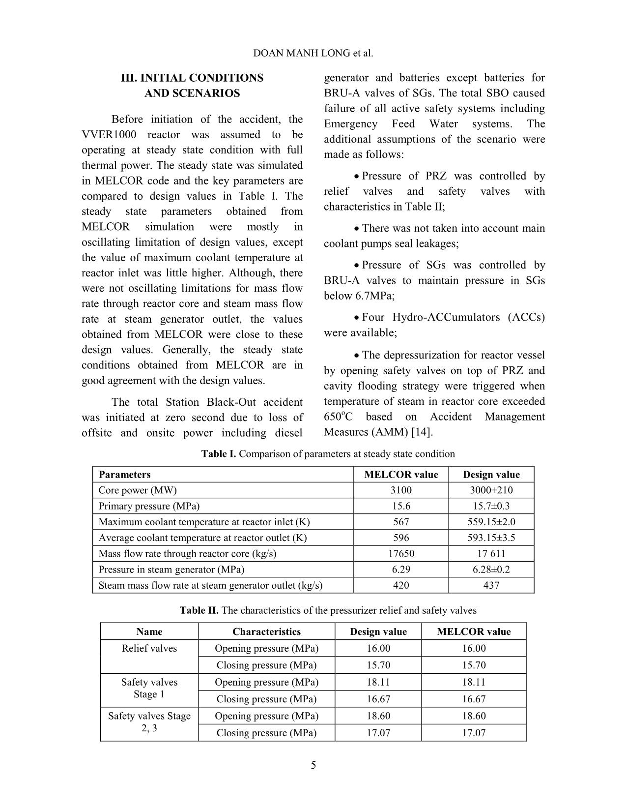
Trang 5
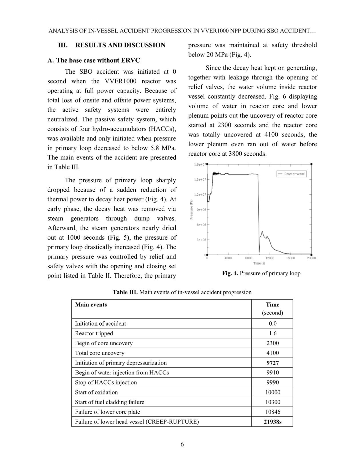
Trang 6
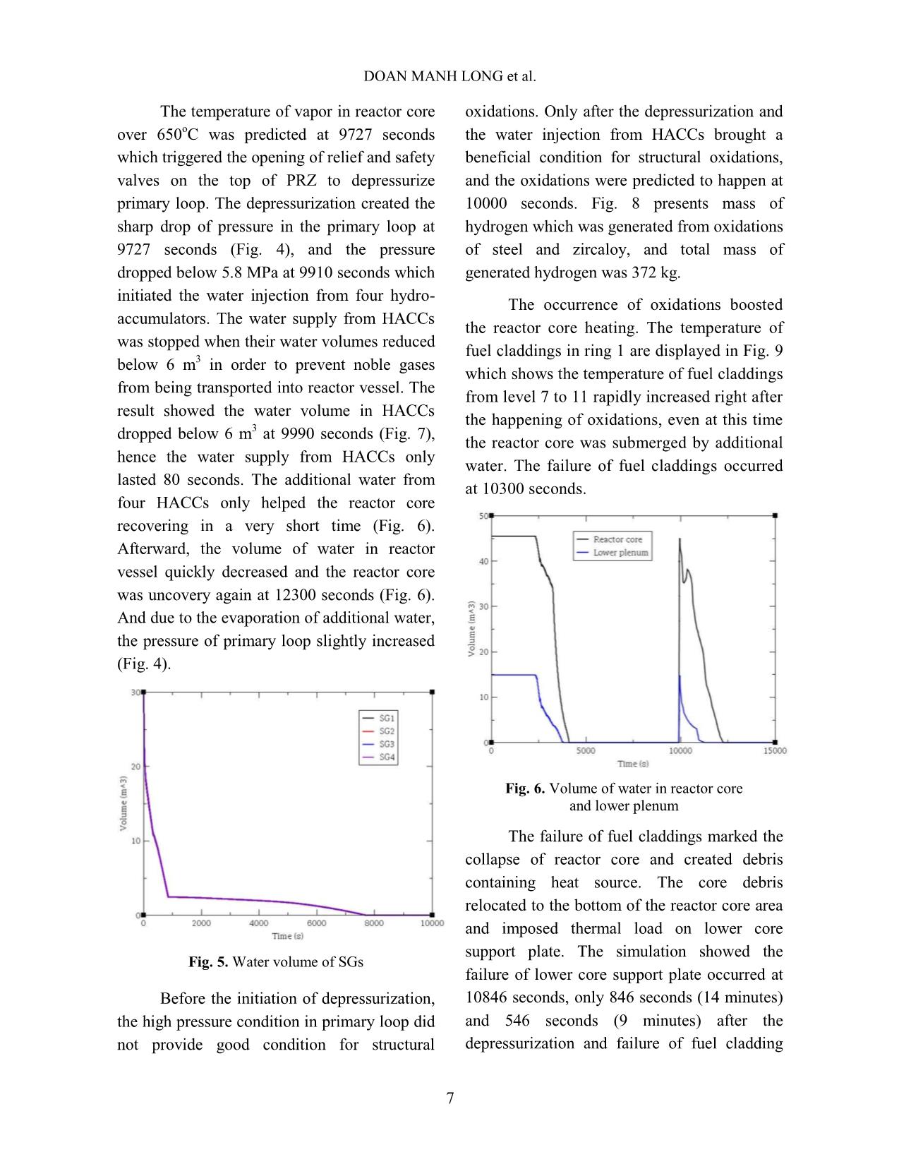
Trang 7
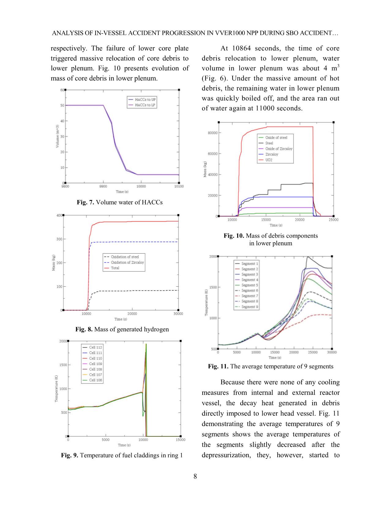
Trang 8
Trang 9
Trang 10
Tải về để xem bản đầy đủ
Tóm tắt nội dung tài liệu: Analysis of in-vessel accident progression in VVER1000 NPP during SBO accident with external reactor vessel cooling method
 of
the segments slightly decreased after the
depressurization, they, however, started to
DOAN MANH LONG et al.
9
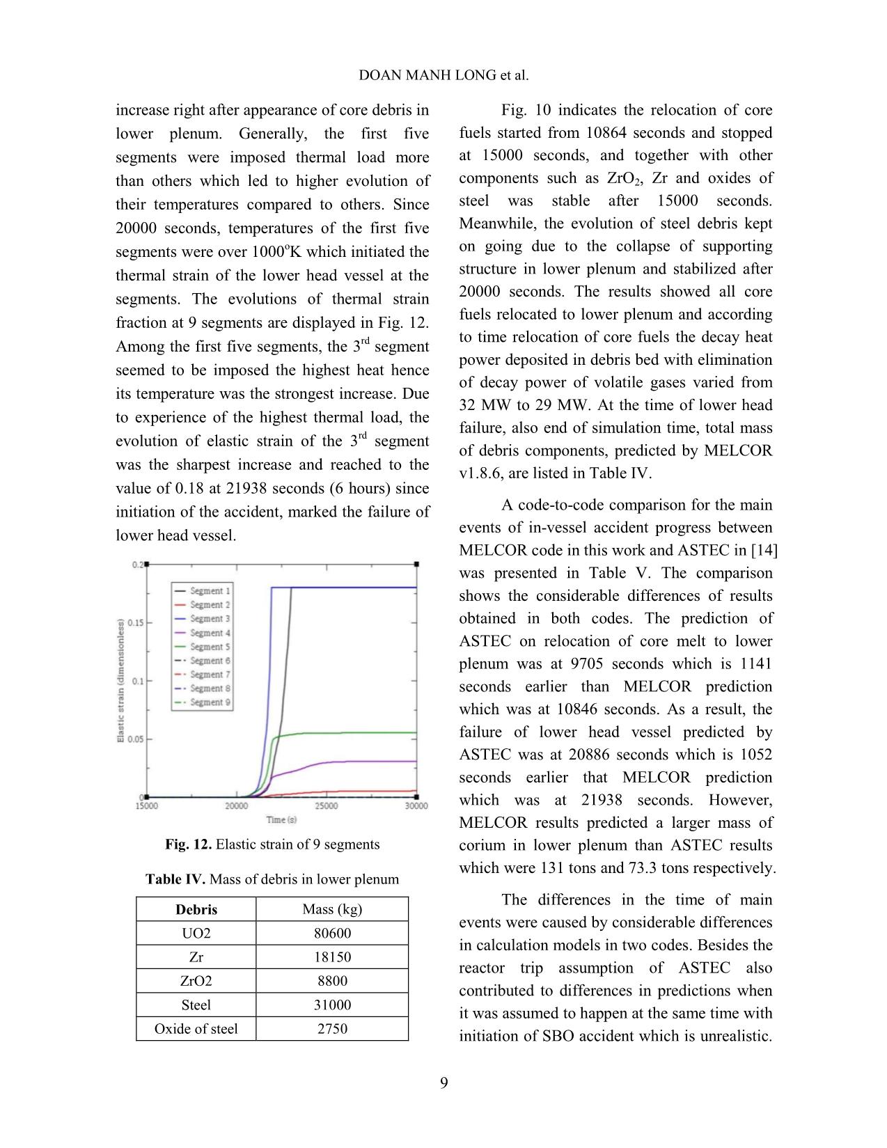
increase right after appearance of core debris in
lower plenum. Generally, the first five
segments were imposed thermal load more
than others which led to higher evolution of
their temperatures compared to others. Since
20000 seconds, temperatures of the first five
segments were over 1000oK which initiated the
thermal strain of the lower head vessel at the
segments. The evolutions of thermal strain
fraction at 9 segments are displayed in Fig. 12.
Among the first five segments, the 3rd segment
seemed to be imposed the highest heat hence
its temperature was the strongest increase. Due
to experience of the highest thermal load, the
evolution of elastic strain of the 3rd segment
was the sharpest increase and reached to the
value of 0.18 at 21938 seconds (6 hours) since
initiation of the accident, marked the failure of
lower head vessel.
Fig. 12. Elastic strain of 9 segments
Table IV. Mass of debris in lower plenum
Debris Mass (kg)
UO2 80600
Zr 18150
ZrO2 8800
Steel 31000
Oxide of steel 2750
Fig. 10 indicates the relocation of core
fuels started from 10864 seconds and stopped
at 15000 seconds, and together with other
components such as ZrO2, Zr and oxides of
steel was stable after 15000 seconds.
Meanwhile, the evolution of steel debris kept
on going due to the collapse of supporting
structure in lower plenum and stabilized after
20000 seconds. The results showed all core
fuels relocated to lower plenum and according
to time relocation of core fuels the decay heat
power deposited in debris bed with elimination
of decay power of volatile gases varied from
32 MW to 29 MW. At the time of lower head
failure, also end of simulation time, total mass
of debris components, predicted by MELCOR
v1.8.6, are listed in Table IV.
A code-to-code comparison for the main
events of in-vessel accident progress between
MELCOR code in this work and ASTEC in [14]
was presented in Table V. The comparison
shows the considerable differences of results
obtained in both codes. The prediction of
ASTEC on relocation of core melt to lower
plenum was at 9705 seconds which is 1141
seconds earlier than MELCOR prediction
which was at 10846 seconds. As a result, the
failure of lower head vessel predicted by
ASTEC was at 20886 seconds which is 1052
seconds earlier that MELCOR prediction
which was at 21938 seconds. However,
MELCOR results predicted a larger mass of
corium in lower plenum than ASTEC results
which were 131 tons and 73.3 tons respectively.
The differences in the time of main
events were caused by considerable differences
in calculation models in two codes. Besides the
reactor trip assumption of ASTEC also
contributed to differences in predictions when
it was assumed to happen at the same time with
initiation of SBO accident which is unrealistic.
ANALYSIS OF IN-
10
In addition, the difference in model of core
debris relocation to lower plenum caused a
significant difference in prediction of mass of
UO2 relocating to lower plenum. In MELCOR
code, the relocation of core debris was
triggered when the lower core support plate
was failed by both mechanical and thermal
load, and when the lower core support plate in
a ring failed and lost capability of supporting,
its entire structure and all material resting on it
would totally collapse and relocate to lower
plenum. Meanwhile, ASTEC code [16] did not
predict the mechanical failure of the lower core
support plate but only its thermal failure, and
the core debris only relocated to lower plenum
by melting the plate and crossing through the
plate hole to lower plenum. In this case,
results of MELCOR simulation showed the
lower core support plate in five rings
completely collapsed, therefore all core fuel
relocated to lower plenum. In case of ASTEC,
the mass of core debris relocating to lower
plenum depended on the size of the hole in the
plate hence somehow the size was not large
enough for all core fuel relocating to lower
plenum in this scenario.
Table V. MELCOR and ASTEC main events
Main events Time (second)
MELCOR ASTEC
Initiation of accident 0.0 0.0
Reactor tripped 1.6 0.0
Opening of steam-dump to atmosphere valves (BRU- A) 8.0 45.0
Begin of core uncovery 2300 -
Heating up of the core 4000 8767
Total core uncovery 4100 -
Steam dry-out 8000 3800.0
Closing of BRU-A valves 8000 7200
Initiation of primary depressurization 9727 10341
Begin of water injection from HACCs 9910 10514
Stop of HACCs injection 9990 17545
First material slump in lower plenum 10846 9705
Failure of lower head vessel (CREEP-RUPTURE) 21938 20886
Total mass of corium in lower head (tons) 131 73.33
B. Deployment of IVR strategy with ERVC
In this study, the external vessel cooling
strategy was adopted in order to cool down
the hot debris from external surface of the
VVER1000 lower head vessel by injecting
water into the cavity. The water injection was
initiated when the vapor temperature in
reactor core exceeded 650oC. The water level
in reactor cavity was maintained at the height
of cold leg. Until now, there has not been
official design of ERVC for VVER1000
reactor. Therefore, the study proposed a
simplified scheme of ERVC strategy for
VVER1000 reactor which included a cooling
channel formed by reactor vessel and a frame
structure, and an unlimited water resource.
Fig. 13 demonstrated a nodalizational scheme
of the ERVC in MELCOR code.
DOAN MANH LONG et al.
11
The SBO accident was re-simulated with
deployment of ERVC strategy. The results
showed the performance of ERVC strategy did
not affect the in-core accident progress. The
evolution of the accident remained the same as
the scenario without implementing ERVC
strategy. A comparison of main events between
two SBO scenarios with and without deploying
IVR strategy is presented in Table VI.
The initiation of ERVC strategy was
simultaneously happened at 9727 seconds with
the primary depressurization when vapor
temperature in reactor core exceeded 650oC.
Fig. 14 demonstrated water level in reactor
cavity and the water level reached the height of
cold leg at 12500 seconds, then it was
maintained at the level. Figs. 15-17 displayed
the temperature of 9 segments of VVER1000
lower head wall in two both scenarios. The
solid lines and the dash lines present the results
of the scenario without ERVC strategy and
with ERVC strategy respectively. The figures
indicate the decrease of temperature of lower
head walls in both cases happened right after
the initiation of depressurization at 9727
seconds. However, in case of implementing
ERVC (dash line) the temperature of lower
head at 9 segments decreased deeper.
Fig. 13. A nodalization for external reactor vessel
cooling strategy
Fig. 14. Water level in cooling channel and cavity
Table VI. Main events of in-vessel accident progression
Main events Time (seconds)
With IVR Without IVR
Initiation of accident 0.0 0.0
Reactor tripped 1.6 1.6
Begin of core uncovery 2300 2300
Total core uncovery 4100 4100
Initiation of primary depressurization 9727 9727
Start of cavity flooding 9727 9727
Begin of water injection from HACCs 9910 9910
Stop of HACCs injection 9990 9990
Start of oxidation 10000 10000
Start of fuel cladding failure 10300 10300
Failure of lower core plate 10846 10846
Failure of lower head vessel (CREEP-RUPTURE) 27341 21938
ANALYSIS OF IN-
12
Fig. 15. Temperature of segments 1-3
Fig. 15 and Fig. 16 indicate the
temperature at segments 1-6 started to increase
at 15000 seconds, and it strongly increased at
17000 seconds. Meanwhile, Fig. 17 shows the
temperature of lower head wall at segments 7-9
was efficiently cooled and kept at low
temperature below 600oC. Together with the
increase of temperature of segments 1-6, the
heat transfer between lower head vessel and
water drastically increased as well, which
caused the vibration of water level in cooling
channel (Fig. 14). Fig. 16 shows the temperature
of segments 4-6 was kept under 1000oK (727oC).
Fig. 16. Evolution of temperature of segments 4-6
However, Fig. 15 indicates the
temperature of segments 1-3 increased beyond
1000oK, among them the temperature of
segments 1 and 3 were beyond 1000oK at
24000 and 26000 seconds respectively which
caused the occurrence of thermal strain of the
segments. Fig. 18 displayed the evolution of
thermal strain fraction of all segments. The
results show the thermal strain of lower head at
segment 1 reached the value of 0.18 at 27341
seconds which marked the failure of
VVER1000 lower head reactor vessel.
Fig. 17. Evolution of temperature of segments 7-9
Fig. 18. Evolution of thermal strain of segments
DOAN MANH LONG et al.
13
IV. CONCLUDING REMARKS
In this paper, the in-vessel accident
progress during the Station Black-Out (SBO)
accident combined with externally vessel
cooling was analyzed for VVER1000 reactor
by using MELCOR v.1.8.6 code. Some
conclusions were given as following:
Under SBO accident, only water
from four hydro-accumulators could not
prevent the collapse of reactor core and
relocation of core debris to lower plenum. The
collapse of reactor core marked by failure of
fuel cladding was occurred at 10300 seconds
(2.86 hours), the appearance of first core debris
in lower plenum was at 10846 seconds (3.01
hours), and all core fuels relocated to lower
plenum at 15000 seconds (4.2 hours). The
decay heat power deposited in debris bed
locating in lower plenum was estimated from
32 to 29 MW with taking the elimination of
decay power of volatile gases into
consideration. All the outcomes would be
significant information for further study on
thermal behavior of debris bed/molten pool in
lower plenum and thermal response of
VVER1000 lower head vessel as well;
In the base case without
implementing IVR strategy, the VVER1000
lower head vessel was failed at 21938 seconds
(6.09 hours) due to thermal creep-rupture.
Meanwhile, in the case of IVR strategy
deployment, the results indicated the strategy
could not prevent VVER1000 lower head
vessel from failure caused by thermal creep-
rupture and only prolonged the existence of
VVER1000 lower head vessel for 5437
seconds (1.5 hours) compared to the base case;
The flat shape of VVER1000 lower
head vessel also raises a concern about the
occurrence of failure at low position when the
critical heat fluxes at the low positions were
low as seen in results of ULPU [7]. The
results of the study also showed the failure of
VVER1000 lower head vessel happened at
low positions, therefore, it is necessary to
optimize geometry of cooling channel for
VVER1000 reactor;
In addition, the comparison on the
main phenomena during accident progress
between MELCOR and ASTEC suggested it is
necessary to take further investigation on in-
vessel accident progression in case of SBO
accident by other severe accident codes in
order to set up a range of key parameters for
the bounding configuration of molten pool in
VVER1000 lower plenum and specify decay
heat power deposited molten pool as well.
ABBREVIATIONS
AMM Accident Management Measures
BRU-A A kind of atmospheric dump
valves of steam generators
CC Cold Collector
CL Cold Leg
CP Cold Part
CV Control Volume
ERVC External Reactor Vessel Cooling
HACCs Hydro-ACCumulators
HC Hot Collector
HL Hot Leg
HP Hot Part
IVR In-Vessel melt Retention
LBLOCA Large Break Lost of Coolant
Accident
LP Lower Plenum
MSH Main Steam Header
NPP Nuclear Power Plant
ANALYSIS OF IN-
14
PORV Pilot-Operated Relief Valve
PRZ PRessuriZer
SBO Station Black-Out
SG Steam Generator
SL Steam Line
UP Upper Plenum
ACKNOWLEDGEMENT
The authors are grateful for financial
funding of Ministry of Science and Technology
and Vietnam Atomic Energy Institute. This
work was performed under ministerial project
on
05/01/2018.
REFERENCES
[1]. Tuomisto, H., and Theofanous, T.G. A
consistent approach to severe accident
management . Nuclear Engineering and
Design 148, 171-183, 1994.
[2]. Kym l inen, O., et al. In-vessel retention of
corium at the Loviisa plant . Nuclear
Engineering and Design, 169, 109-130, 1997.
[3]. Theofanous, T.G., et al. In-vessel cool-ability
and retention of a core melt , DOE/ID-10460,
Volume 1, Revised October, 1996.
[4]. Esmaili, H., and Khatib-Rahbar, M. Analysis of
in-vessel retention and ex-vessel fuel coolant
interaction for AP1000 . Energy Research, Inc.,
ERI/NRC 04-21, NUREG/CR-6849, 2004.
[5]. Rempe, J.L., et al. In Vessel Retention
strategy for higher power reactors . Final
Report, INEEL/EXT-04-02561, 2005.
[6]. Ji Xing et al. HPR1000: Advanced
pressurized water reactor with Active and
Passive safety Engineering 2 79-87, 2016.
[7]. Theofanous, T.G., et al. In-vessel cool-ability
and retention of a core melt , DOE/ID-10460,
Volume 1, Revised October, 1996.
[8]. Esmaili, H., et al. An Assessment of Ex-
Vessel Steam Explosions in the AP600
Advanced Pressurized Water Reactor , Energy
Research, Inc., ERI/NRC 95-211, 1996.
[9]. Bui and Dinh. Modeling of heat transfer in
heated-generating liquid pools by an effective
diffusivity-convectivity approach , In:
Proceedings of 2nd European Thermal-Sciences
Conference, Rome, Italy, pp. 1365 1372, 1992.
[10].Tran, C.T., and Dinh, T.N. The effective
convectivity model for simulations of melt
pool heat transfer in a light water reactor
pressure vessel lower head . Part I&II.
Progress in Nuclear Energy 51, 849 871, 2009.
[11].Dombrovskii, L.A., et al. Numerical
Simulation of the Stratified-Corium
Temperature Field and Melting of the Reactor
Vessel for a Severe Accident in a Nuclear
Power Station . Thermal Engineering, Vol. 45,
No. 9, pp. 775-765, 1998.
[12]. Yue Jin et al. In-and ex-vessel coupled analysis of
IVR-ERVC phenomenon for large scale PWR .
Annals of Nuclear Energy 80 322-337, 2015.
[13].SANGIORGI Marco et al. In-Vessel Melt
Retention Analysis of a VVER1000 NPP .
EUR 27951; doi 10.2790/62596, 2016.
[14].Polina Tusheva et al. Analysis of severe
accidents in VVER1000 reactors using integral
code ASTEC . Proceeding of the 17th
International Conference on Nuclear
Engineering, Brussels, Belgium, 2009.
[15].Sandia National Laboratories, MELCOR
computer code manuals , Ver.1.8.6, Rev.3 vol.
NUREG/CG 6119, 2005.
[16].Belon, S., et al. Insight of core degradation
simulation in integral codes throughout
ASTEC/MELCOR crosswalk comparisons and
ASTEC sensitivities studies . The 8th
European Review Meeting on Severe Accident
Research, Warsaw, Poland, 2017.
File đính kèm:
 analysis_of_in_vessel_accident_progression_in_vver1000_npp_d.pdf

