Reactivity induced transient analysis when the occurrence of leakage in the dry irradiation channels of the Dalat Nuclear Research Reactor
The leakage from the reactor pool back into the dry irradiation channels due to corrosion or
mechanics based reason is a postulated event that could occur under operating conditions of the Dalat
nuclear research reactor (DNRR), especially the channel 7-1 which has been installed more than 30
years. When it occurs, the air space in these channels will be occupied by the water, subsequently a
water column will appear in fuel region. The appearance of water column considerably enhances
medium of neutron moderation for its surrounding fuel assemblies. As a result, a positive reactivity is
inserted in the core and this event is classified as an insertion of excess reactivity. This event needs to
be addressed by analysis and assessment from safety point of view and the results of analysis are also
important for updating the reactor operating procedures. This paper presents assumptions, computer
models and the results of analysis for such event in the DNRR by using MCNP5 code (code for
neutronics analysis) and EUREKA-2/RR code (code for transient analysis). The calculation results
include value of reactivity insertion, change in power of reactor, as well as surface temperature of the
hottest fuel assembly. This research contributes to updating the reactor operating procedure.
Trang 1
Trang 2
Trang 3
Trang 4
Trang 5
Trang 6
Trang 7
Trang 8
Trang 9
Tóm tắt nội dung tài liệu: Reactivity induced transient analysis when the occurrence of leakage in the dry irradiation channels of the Dalat Nuclear Research Reactor
 irradiation channels
of the Dalat Nuclear Research Reactor
Dau Duc Tu, Nguyen Minh Tuan, Le Vinh Vinh, Huynh Ton Nghiem,
Nguyen Kien Cuong, Tran Quoc Duong, Bui Phuong Nam
Reactor Center, Dalat Nuclear Research Institute, VINATOM
01 Nguyen Tu Luc Str., Dalat, Lamdong, Vietnam.
E-mail: tudd.re@dnri.vn
(Received 06 December 2018, accepted 28 December 2018)
Abstract: The leakage from the reactor pool back into the dry irradiation channels due to corrosion or
mechanics based reason is a postulated event that could occur under operating conditions of the Dalat
nuclear research reactor (DNRR), especially the channel 7-1 which has been installed more than 30
years. When it occurs, the air space in these channels will be occupied by the water, subsequently a
water column will appear in fuel region. The appearance of water column considerably enhances
medium of neutron moderation for its surrounding fuel assemblies. As a result, a positive reactivity is
inserted in the core and this event is classified as an insertion of excess reactivity. This event needs to
be addressed by analysis and assessment from safety point of view and the results of analysis are also
important for updating the reactor operating procedures. This paper presents assumptions, computer
models and the results of analysis for such event in the DNRR by using MCNP5 code (code for
neutronics analysis) and EUREKA-2/RR code (code for transient analysis). The calculation results
include value of reactivity insertion, change in power of reactor, as well as surface temperature of the
hottest fuel assembly. This research contributes to updating the reactor operating procedure.
Keywords: Dalat nuclear research reactor (DNRR), MCNP5, EUREKA-2/RR, reactivity
insertion, transient analysis.
I. INTRODUCTION
A. General information
The Dalat reactor, which is a swimming
pool type reactor and uses light water as
moderator and coolant, has 500 kW thermal
power and put into operation in March, 1984. It
was reconstructed and upgraded from the USA
made 250 kW TRIGA reactor. A number of
structures from the original TRIGA reactor such
as the aluminum tank with the surrounding
concrete shield, four beam-ports, thermal
column and the graphite reflector were
remained.
The reactor core is currently loaded 92
low enriched fuel (LEU) assemblies (19.75%),
3 irradiation channels (2 dry channels and 1
wet channel), 12 beryllium rods and a neutron
trap [1]. The fuel assemblies are VVR-M2
tubular fuel assemblies designed
and manufactured in Russia. Each fuel
assembly consists of three coaxial annular
tubes as well as a header and a tail. The
outermost fuel element has a hexagonal shape
of 32 mm in width across parallel sides and the
other two inner ones have a circular shape of
22 mm and 11 mm in outer diameter,
respectively. The beryllium rods of the reactor
have a hexagonal shape of 32 mm in width
across its parallel sides [1].
B. Description of dry irradiation channels
In the reactor core, there are two dry
irradiation channels located in cells 7-1 and 13-
REACTIVITY INDUCED TRANSIENT ANALYSIS WHEN THE OCCURRENCE OF
2
2 and designed for neutron activation analysis
(NAA). Their characteristics are described in
Table I. They are vertical channels and made
of watertight aluminum tubes. Samples for
NAA are packaged in small plastic bags and
then placed in a high purity polyethylene
irradiation capsule (so-called rabbit). Finally,
the capsules are sent to and returned from the
channels by a pneumatic transfer system
(PTS). At these two channels, samples are
irradiated for a short time from 5 seconds to 5
minutes to analyze elements by measuring
emission ray gamma spectrum of the short-
lived radionuclides. The PTS of channel 7-1 is
a remote-control system located nearby the
reactor building. The PTS of channel 13-2 is
mainly used for fast analysis of elements. Its
terminal station and measuring equipments are
located in the reactor building [2]. These
channels enter the reactor from the top surface
of the reactor pool, pass through the pool,
penetrate into cells 7-1 and 13-2 of the reactor
core and terminate 25 cm from the bottom of
the reactor core as shown in Figures 1 and 2.
Table I. Characteristics of the dry vertical irradiation channels
Characteristics Channel 7-1 Channel 13-2
Thermal neutron flux, n/cm
2
/s (3.8 ÷ 4.4) 1012 (3.8 ÷ 4.2) 1012
Epithermal neutron flux, n/cm
2
/s (4.0 ÷ 4.5) 1011 (3.7 ÷ 4.1) 1011
Fast neutron flux, n/cm
2
/s (3.0 ÷ 5.0) 1012 (3.0 ÷ 6.0) 1012
Loading capacity, gram 20 4
Irradiation time (min.), sec 45 5
Irradiation time (max.), min. 20 30
Sample moving speed, m/s 10 20
Fig. 1. Technical drawing of pneumatic transfer channel 13-2 [2]
DAU DUC TU et al.
3
Fig. 2. The layout of pneumatic transfer systems (PTS) [2]
C. The leakage and assumptions for the
transient analysis
Under normal operating conditions, the
leakage from the reactor pool back into the
pneumatic irradiation channels due to
corrosion or mechanics based reasons is a
postulated event that could occur at the DNRR.
When it occurs, the air space in these channels
will be occupied by the water, subsequently a
water column will appear in fuel region. The
appearance of water column considerably
enhances medium of neutron moderation for its
surrounding fuel assemblies. As a result, a
positive reactivity is inserted in the core that
leads to an unwanted increase in fission rate,
reactor power and fuel temperature. The value
and speed of reactivity insertion mainly depend
on the leakage rate, volume and location of the
channels, power level and coolant temperature,
etc. This event is classified as an event of
insertion of excess reactivity. The events of
insertion of excess reactivity that has the most
potential consequences as a shim rod (SR) or
the automatic regulating rod (AR) of the
reactor can be withdrawn with the maximum
speed of 3.4 mm/s and 20 mm/s, respectively,
has been analyzed and described in the safety
analysis report (SAR) for the DNRR [2].
However, the event presented here has not
been analyzed in detail so far and the result of
this analysis is important to develop and update
the DNRR operating procedures after 35 years
of operation.
The main assumption selected for
transient analysis is a small break occurring at
one of two dry irradiation channels (channel 7-
1 or 13-2) with diameter of 2 mm (Ø = 2 mm)
when the reactor is operating at the nominal
power (500 kW). This assumption was made in
order to simulate the above mentioned leakage.
The other physics parameters needed for the
transient analysis are given in Table II.
MCNP5 Monte Carlo code and ENDF/B-VII.0
nuclear data library were used to analyze
reactivity insertion and EUREKA-2/RR code
was used to study the transient of core power
and fuel surface temperature. In fact, the
possibility of simultaneous leakage at the 2 dry
channels is extremely low; therefore it was not
included in this investigation.
II. CALCULATION MODELS
In the investigation, the reactor core and
its components such as fuel assemblies, control
rods, beryllium blocks, graphite reflector, beam
ports, thermal column, etc. were modeled
almost as exactly as they are. Figures 3 and 4
show in detail MCNP5 model for the core
configuration with 92 fuel assemblies of low
enriched fuel (LEU) and the irradiation
channels of the DNRR [3].
REACTIVITY INDUCED TRANSIENT ANALYSIS WHEN THE OCCURRENCE OF
4
Table II. Summary of the reactor and safety parameters needed for the transient analysis
Parameters Values
Power, kW 500
Coolant inlet temperature,
o
C 32
Reactor kinetics parameters
- Prompt neutron life, s 8.925 10-5
- Delayed neutron fraction (1$) 7.551 10-3
Temperature reactivity coefficients
- Moderator, (ΔK/K); (293 - 400oK) - 1.264 10-2
- Fuel, (ΔK/K)/oC;
 (293 - 400
o
K) - 1.86 10-3
 (400 - 500
o
K) - 1.92 10-3
 (500 - 600
o
K) - 1.56 10-3
- Void, ΔK/K % of void
 (0 - 5%) -0.2432
 (5 - 10%) -0.2731
 (10 - 20%) -0.3097
Reactivity control
- Shutdown worth, % (2 safety rods) 4.98
- Maximum withdrawal speed of one shim rod,
mm/s
3.4
 and of the regulating rod, mm/s 20
Reactor protection characteristics
- Response time to overpower scram, s 0.16
- Response time to fast period scram, s
 Start-up range 9.1
 Working range 6.7
- Drop time of control rods, s 0.67
Fig. 3. Cross-sectional and vertical views of the reactor modeled by MCNP5
Channel No.2
Channel No.1
Channel No.3
Channel No.4
DAU DUC TU et al.
5
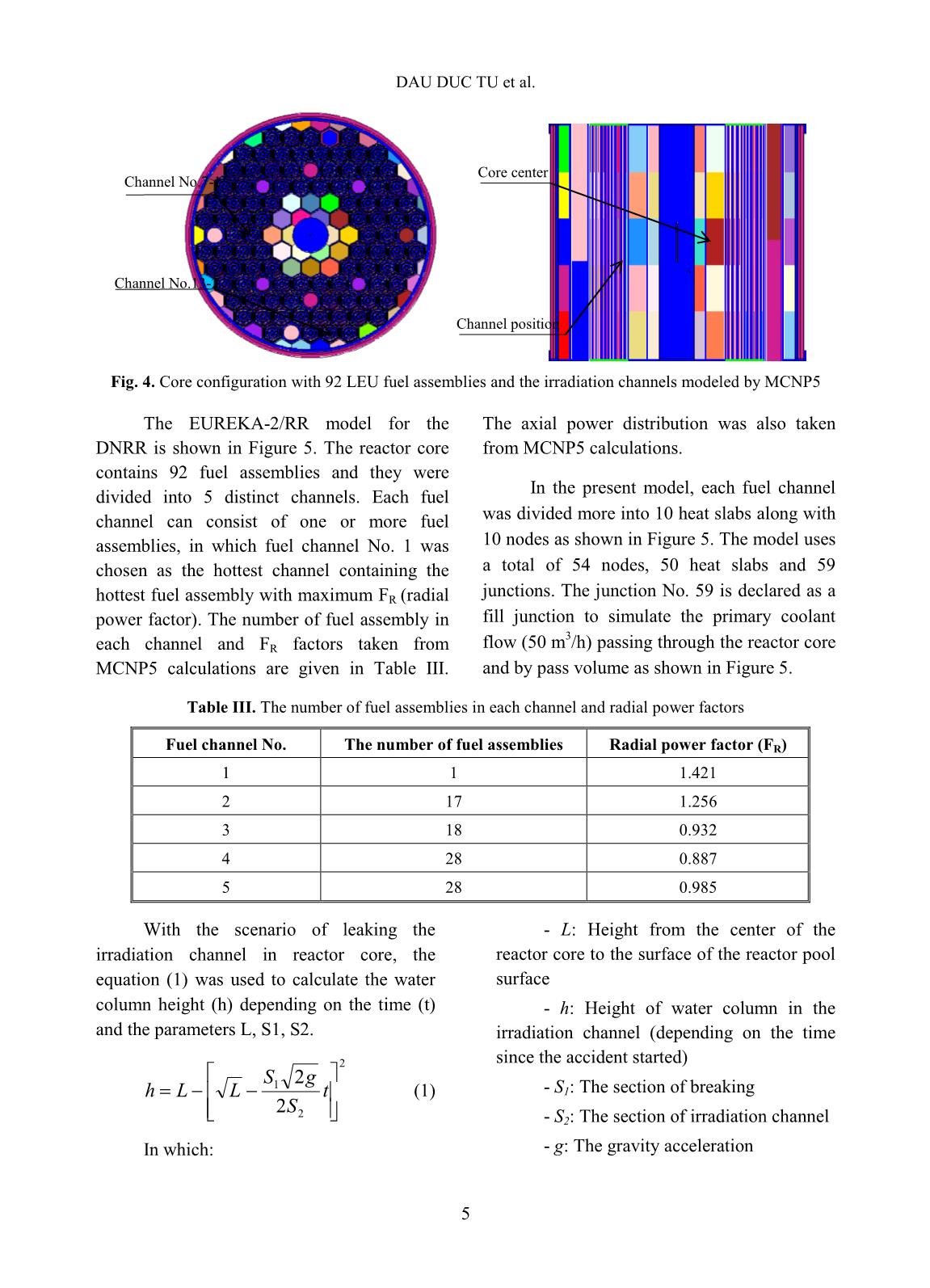
Fig. 4. Core configuration with 92 LEU fuel assemblies and the irradiation channels modeled by MCNP5
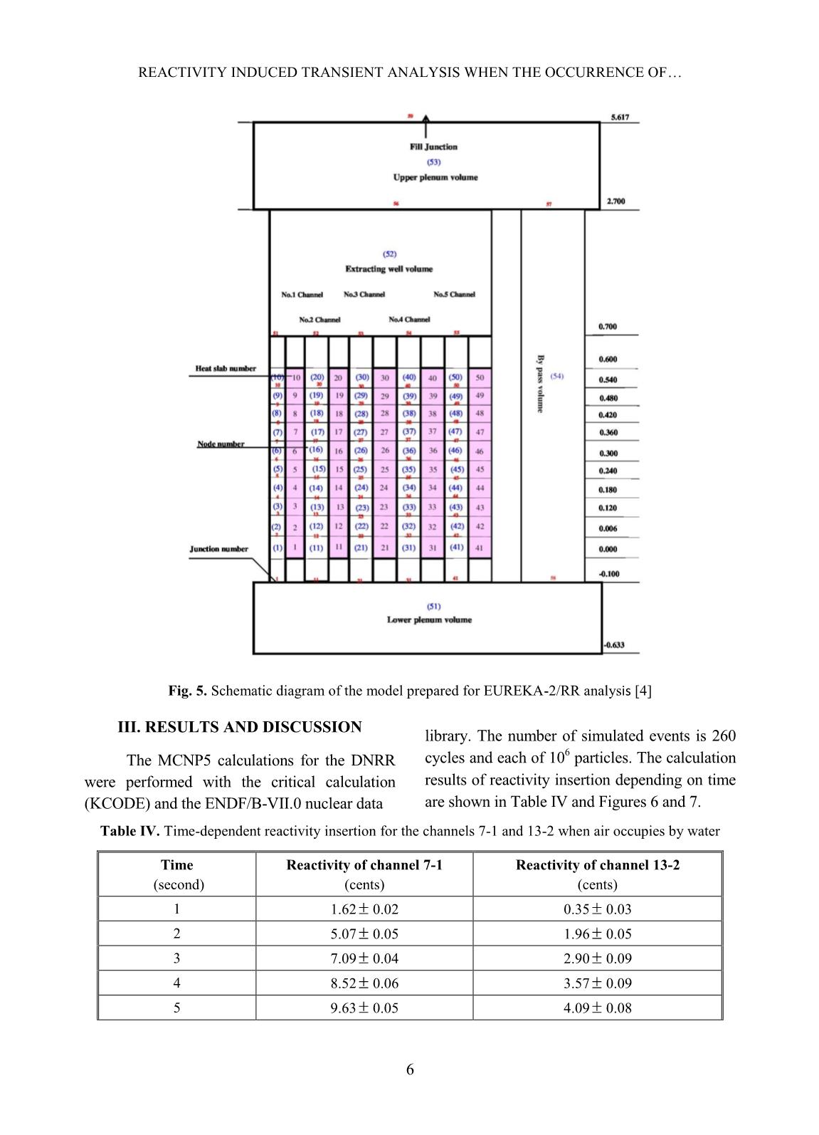
The EUREKA-2/RR model for the
DNRR is shown in Figure 5. The reactor core
contains 92 fuel assemblies and they were
divided into 5 distinct channels. Each fuel
channel can consist of one or more fuel
assemblies, in which fuel channel No. 1 was
chosen as the hottest channel containing the
hottest fuel assembly with maximum FR (radial
power factor). The number of fuel assembly in
each channel and FR factors taken from
MCNP5 calculations are given in Table III.
The axial power distribution was also taken
from MCNP5 calculations.
In the present model, each fuel channel
was divided more into 10 heat slabs along with
10 nodes as shown in Figure 5. The model uses
a total of 54 nodes, 50 heat slabs and 59
junctions. The junction No. 59 is declared as a
fill junction to simulate the primary coolant
flow (50 m
3
/h) passing through the reactor core
and by pass volume as shown in Figure 5.
Table III. The number of fuel assemblies in each channel and radial power factors
Fuel channel No. The number of fuel assemblies Radial power factor (FR)
1 1 1.421
2 17 1.256
3 18 0.932
4 28 0.887
5 28 0.985
With the scenario of leaking the
irradiation channel in reactor core, the
equation (1) was used to calculate the water
column height (h) depending on the time (t)
and the parameters L, S1, S2.
2
2
1
2
2
 t
S
gS
LLh (1)
In which:
- L: Height from the center of the
reactor core to the surface of the reactor pool
surface
- h: Height of water column in the
irradiation channel (depending on the time
since the accident started)
- S1: The section of breaking
- S2: The section of irradiation channel
- g: The gravity acceleration
Channel No.7-1
Channel No.13-2
Channel position
Core center
REACTIVITY INDUCED TRANSIENT ANALYSIS WHEN THE OCCURRENCE OF
6
Fig. 5. Schematic diagram of the model prepared for EUREKA-2/RR analysis [4]
III. RESULTS AND DISCUSSION
The MCNP5 calculations for the DNRR
were performed with the critical calculation
(KCODE) and the ENDF/B-VII.0 nuclear data
library. The number of simulated events is 260
cycles and each of 10
6
 particles. The calculation
results of reactivity insertion depending on time
are shown in Table IV and Figures 6 and 7.
Table IV. Time-dependent reactivity insertion for the channels 7-1 and 13-2 when air occupies by water
Time
 (second)
Reactivity of channel 7-1
(cents)
Reactivity of channel 13-2
(cents)
1 1.62 0.02 0.35 0.03
2 5.07 0.05 1.96 0.05
3 7.09 0.04 2.90 0.09
4 8.52 0.06 3.57 0.09
5 9.63 0.05 4.09 0.08
DAU DUC TU et al.
7
6 10.54 0.07 4.51 0.06
7 11.31 0.07 4.87 0.05
8 11.97 0.06 5.18 0.06
9 12.55 0.04 5.46 0.08
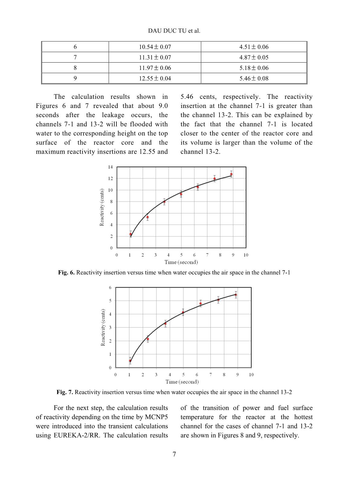
The calculation results shown in
Figures 6 and 7 revealed that about 9.0
seconds after the leakage occurs, the
channels 7-1 and 13-2 will be flooded with
water to the corresponding height on the top
surface of the reactor core and the
maximum reactivity insertions are 12.55 and
5.46 cents, respectively. The reactivity
insertion at the channel 7-1 is greater than
the channel 13-2. This can be explained by
the fact that the channel 7-1 is located
closer to the center of the reactor core and
its volume is larger than the volume of the
channel 13-2.
Fig. 6. Reactivity insertion versus time when water occupies the air space in the channel 7-1
Fig. 7. Reactivity insertion versus time when water occupies the air space in the channel 13-2
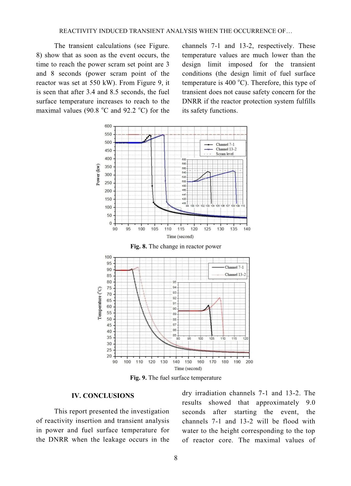
For the next step, the calculation results
of reactivity depending on the time by MCNP5
were introduced into the transient calculations
using EUREKA-2/RR. The calculation results
of the transition of power and fuel surface
temperature for the reactor at the hottest
channel for the cases of channel 7-1 and 13-2
are shown in Figures 8 and 9, respectively.
REACTIVITY INDUCED TRANSIENT ANALYSIS WHEN THE OCCURRENCE OF
8
The transient calculations (see Figure.
8) show that as soon as the event occurs, the
time to reach the power scram set point are 3
and 8 seconds (power scram point of the
reactor was set at 550 kW). From Figure 9, it
is seen that after 3.4 and 8.5 seconds, the fuel
surface temperature increases to reach to the
maximal values (90.8
o
C and 92.2
o
C) for the
channels 7-1 and 13-2, respectively. These
temperature values are much lower than the
design limit imposed for the transient
conditions (the design limit of fuel surface
temperature is 400
o
C). Therefore, this type of
transient does not cause safety concern for the
DNRR if the reactor protection system fulfills
its safety functions.
Fig. 8. The change in reactor power
Fig. 9. The fuel surface temperature
IV. CONCLUSIONS
This report presented the investigation
of reactivity insertion and transient analysis
in power and fuel surface temperature for
the DNRR when the leakage occurs in the
dry irradiation channels 7-1 and 13-2. The
results showed that approximately 9.0
seconds after starting the event, the
channels 7-1 and 13-2 will be flood with
water to the height corresponding to the top
of reactor core. The maximal values of
DAU DUC TU et al.
9
reactivity insertion determined by MCNP5
for the channels 7-1 and 13-2 were
12.55 0.04 and 5.46 0.08 cents,
respectively. The transient analysis by
EUREKA-2/RR showed that the fuel surface
temperature does not exceed 92.2
o
C that is
very low compared to design limit (400
o
C).
 The results of this investigation are
considered to update the operating procedures
of the DNRR after 35 years of operation.
REFERENCE
[1]. Nuclear Research Institute, Regulations of
operation of Dalat nuclear reactor, March 2014.
[2]. Nuclear Research Institute, Safety analysis
report for the Dalat nuclear reactor, 2012.
[3]. MCNP - A General Monte Carlo N-Particle
Transport Code, Version 5, April, 2003.
[4]. EUREKA-2/RR: A Computer Code for the
Reactivity Accident Analyses in Research
Reactors, Private Communication.
File đính kèm:
 reactivity_induced_transient_analysis_when_the_occurrence_of.pdf

