Reactive power compensation in distributed system using centralized control
In technology development, the electric devices (loads) require higher voltage quality.
Maintaining the voltage quality always at a high level will help electric devices perform
the highest efficiency, prolong, and decrease losses. Notwithstanding, it is complex to
solve voltage quality problem because it contains several minor problems as voltage
deviation, voltage fluctuation, flicker, harmonic, asymmetric voltage [1]. There are also a
bunch of ways to deal with voltage regulation. For the case which needs to adjust quickly,
Static Var Compensator (SVC) or STATCOM will be used. However, both of them are
centralized devices while the loads are distributed in plural types and locate at different
positions. The loads are often accessed from a common connection point via transmission
line (TL). On these TLs, the voltage attenuation and heat loss will occur. The centralized
voltage control devices such as SVC or STATCOM could not reduce the TLs losses and it
is difficult to calculate required voltage in each load [2].
Therefore, the aim of this paper is to propose a system of voltage control distributed
devices using centralized control in order to increase the efficiency of the voltage quality’s
adjustment and improvement on specific load in factories [3, 4]. By this solution, active
power’s loss is decreased; the electric device’s performance is higher and prolongs their
longevity [4].
Trang 1
Trang 2
Trang 3
Trang 4
Trang 5
Trang 6
Trang 7
Trang 8
Trang 9
Trang 10
Tải về để xem bản đầy đủ
Tóm tắt nội dung tài liệu: Reactive power compensation in distributed system using centralized control
lectric devices perform
the highest efficiency, prolong, and decrease losses. Notwithstanding, it is complex to
solve voltage quality problem because it contains several minor problems as voltage
deviation, voltage fluctuation, flicker, harmonic, asymmetric voltage [1]. There are also a
bunch of ways to deal with voltage regulation. For the case which needs to adjust quickly,
Static Var Compensator (SVC) or STATCOM will be used. However, both of them are
centralized devices while the loads are distributed in plural types and locate at different
positions. The loads are often accessed from a common connection point via transmission
line (TL). On these TLs, the voltage attenuation and heat loss will occur. The centralized
voltage control devices such as SVC or STATCOM could not reduce the TLs losses and it
is difficult to calculate required voltage in each load [2].
Therefore, the aim of this paper is to propose a system of voltage control distributed
devices using centralized control in order to increase the efficiency of the voltage quality’s
adjustment and improvement on specific load in factories [3, 4]. By this solution, active
power’s loss is decreased; the electric device’s performance is higher and prolongs their
longevity [4].
2. VOLTAGE REGULATION DISTRIBUTED SYSTEM USING CENTRALIZED
CONTROL
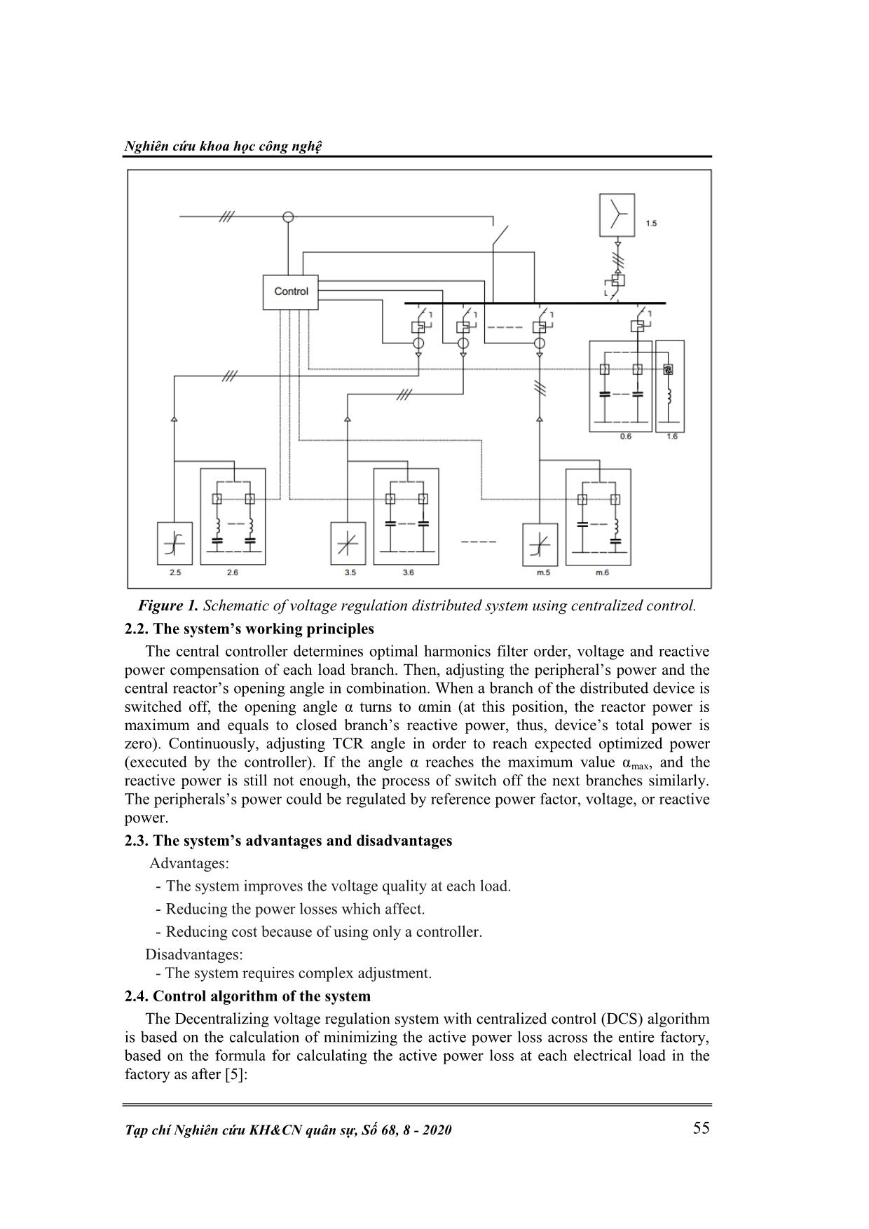
Figure. 1 illustrates a voltage regulation distributed system using centralized control.
2.1. The main elements of system
- The controller: including power measurement systems through current and voltage
signals in each branch. The voltage regulation process will be calculated by changing
both central and peripheral equipments power.
- Central control reactor 1.6: is the Thyristor Control Reactor (TCR) device basically.
To combine switch on/off peripherals and vary TCR opening phase angle, the
device’s power is adjusted smoothly.
- Central reactive power compensation device 0.6: to add needed-power for voltage
regulation system or replacing a device which has a failure.
- The peripherals 2.6, 3.6, m.6 are the hamonics filters, capacitors or mixed harmonic
filter and capacitor that switch on/off based on harmonic order at distributed load
system 2.5, 3.5, m.5 (non linear, linear and mixed none linear, linear loads
respectively). 1.5 is unbalanced load which is close in distance with transformer.
Nghiên cứu khoa học công nghệ
Tạp chí Nghiên cứu KH&CN quân sự, Số 68, 8 - 2020 55
Figure 1. Schematic of voltage regulation distributed system using centralized control.
2.2. The system’s working principles
The central controller determines optimal harmonics filter order, voltage and reactive
power compensation of each load branch. Then, adjusting the peripheral’s power and the
central reactor’s opening angle in combination. When a branch of the distributed device is
switched off, the opening angle α turns to αmin (at this position, the reactor power is
maximum and equals to closed branch’s reactive power, thus, device’s total power is
zero). Continuously, adjusting TCR angle in order to reach expected optimized power
(executed by the controller). If the angle α reaches the maximum value αmax, and the
reactive power is still not enough, the process of switch off the next branches similarly.
The peripherals’s power could be regulated by reference power factor, voltage, or reactive
power.
2.3. The system’s advantages and disadvantages
 Advantages:
- The system improves the voltage quality at each load.
- Reducing the power losses which affect.
- Reducing cost because of using only a controller.
Disadvantages:
- The system requires complex adjustment.
2.4. Control algorithm of the system
The Decentralizing voltage regulation system with centralized control (DCS) algorithm
is based on the calculation of minimizing the active power loss across the entire factory,
based on the formula for calculating the active power loss at each electrical load in the
factory as after [5]:
Kỹ thuật điều khiển & Điện tử
N. T. Dung, D. N. Quang, P. T. Dung, “Reactive power  using centralized control.” 56
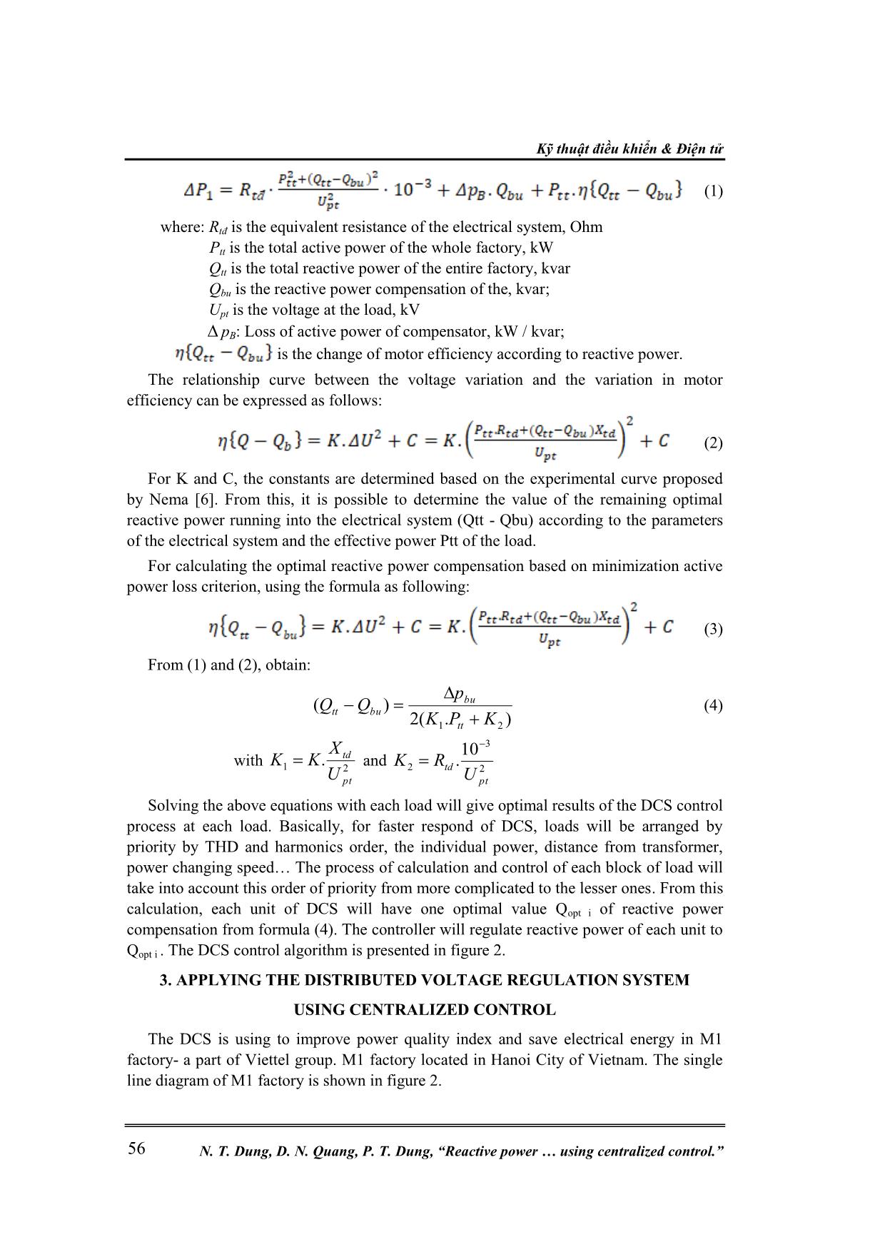
 (1)
where: Rtđ is the equivalent resistance of the electrical system, Ohm
 Ptt is the total active power of the whole factory, kW
 Qtt is the total reactive power of the entire factory, kvar
 Qbu is the reactive power compensation of the, kvar;
 Upt is the voltage at the load, kV
 pB: Loss of active power of compensator, kW / kvar;
 is the change of motor efficiency according to reactive power.
The relationship curve between the voltage variation and the variation in motor
efficiency can be expressed as follows:
 (2)
For K and C, the constants are determined based on the experimental curve proposed
by Nema [6]. From this, it is possible to determine the value of the remaining optimal
reactive power running into the electrical system (Qtt - Qbu) according to the parameters
of the electrical system and the effective power Ptt of the load.
For calculating the optimal reactive power compensation based on minimization active
power loss criterion, using the formula as following:
 (3)
From (1) and (2), obtain:
).(2
)(
21 KPK
p
QQ
tt
bu
butt
 (4)
with
21
.
pt
td
U
X
KK and
2
3
2
10
.
pt
td
U
RK
Solving the above equations with each load will give optimal results of the DCS control
process at each load. Basically, for faster respond of DCS, loads will be arranged by
priority by THD and harmonics order, the individual power, distance from transformer,
power changing speed The process of calculation and control of each block of load will
take into account this order of priority from more complicated to the lesser ones. From this
calculation, each unit of DCS will have one optimal value Qopt i of reactive power
compensation from formula (4). The controller will regulate reactive power of each unit to
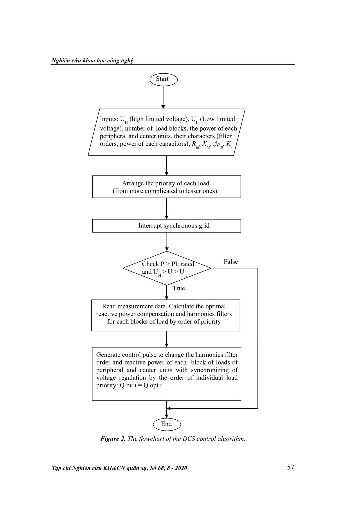
Qopt i . The DCS control algorithm is presented in figure 2.
3. APPLYING THE DISTRIBUTED VOLTAGE REGULATION SYSTEM
USING CENTRALIZED CONTROL
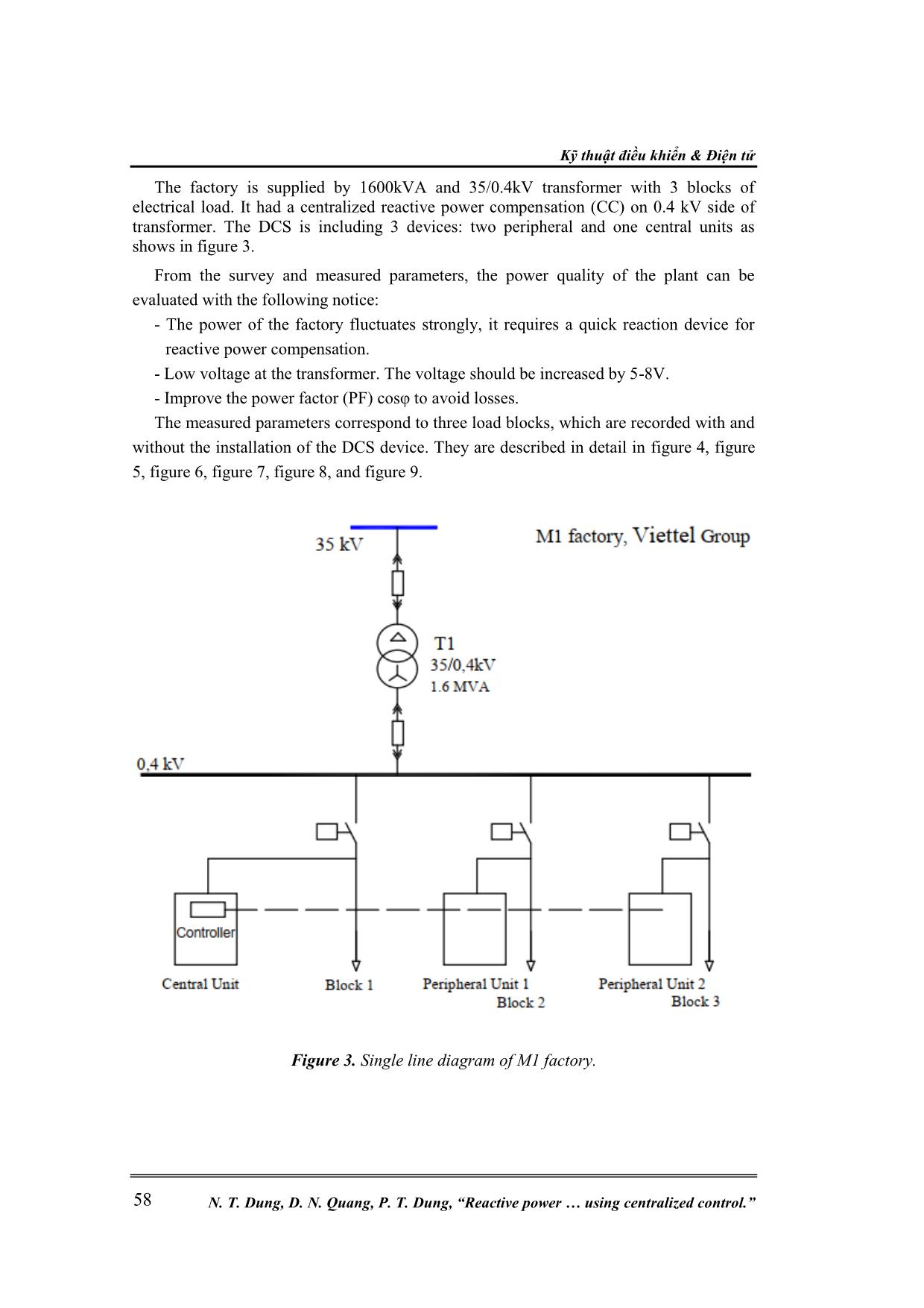
The DCS is using to improve power quality index and save electrical energy in M1
factory- a part of Viettel group. M1 factory located in Hanoi City of Vietnam. The single
line diagram of M1 factory is shown in figure 2.
Nghiên cứu khoa học công nghệ
Tạp chí Nghiên cứu KH&CN quân sự, Số 68, 8 - 2020 57
Figure 2. The flowchart of the DCS control algorithm.
Start
Interrupt synchronous grid
Check P > PL rated
and U
H
> U > U
L
False
True
End
Inputs: U
H
 (high limited voltage), U
L
 (Low limited
voltage), number of load blocks, the power of each
peripheral and center units, their characters (filter
orders, power of each capacitors), R
td
, X
td
, Δp
B
, K
i
Arrange the priority of each load
(from more complicated to lesser ones).
Read measurement data. Calculate the optimal
reactive power compensation and harmonics filters
for each blocks of load by order of priority
Generate control pulse to change the harmonics filter
order and reactive power of each block of loads of
peripheral and center units with synchronizing of
voltage regulation by the order of individual load
priority: Q bu i = Q opt i
Kỹ thuật điều khiển & Điện tử
N. T. Dung, D. N. Quang, P. T. Dung, “Reactive power  using centralized control.” 58
The factory is supplied by 1600kVA and 35/0.4kV transformer with 3 blocks of
electrical load. It had a centralized reactive power compensation (CC) on 0.4 kV side of
transformer. The DCS is including 3 devices: two peripheral and one central units as
shows in figure 3.
From the survey and measured parameters, the power quality of the plant can be
evaluated with the following notice:
- The power of the factory fluctuates strongly, it requires a quick reaction device for
reactive power compensation.
- Low voltage at the transformer. The voltage should be increased by 5-8V.
- Improve the power factor (PF) cosφ to avoid losses.
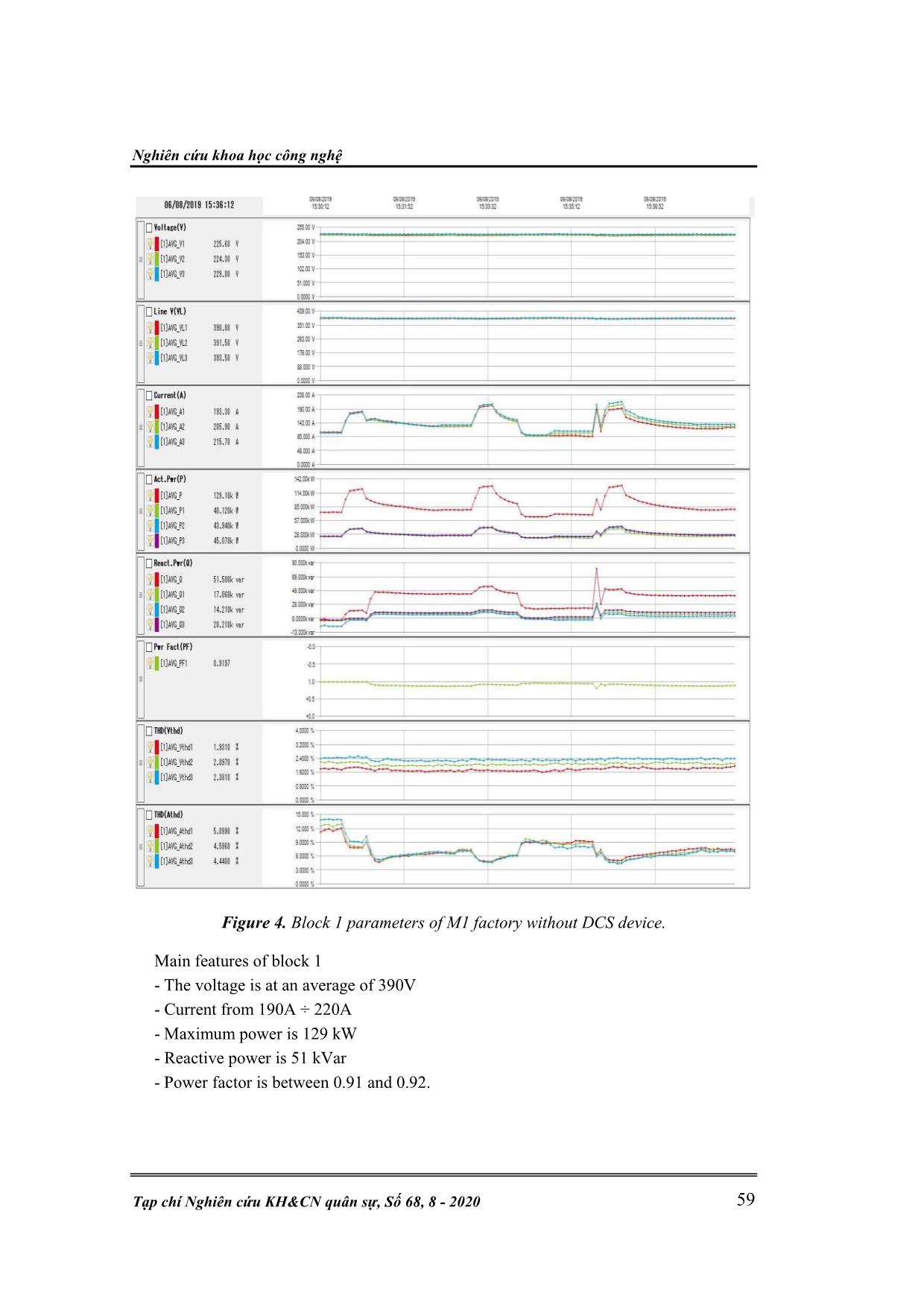
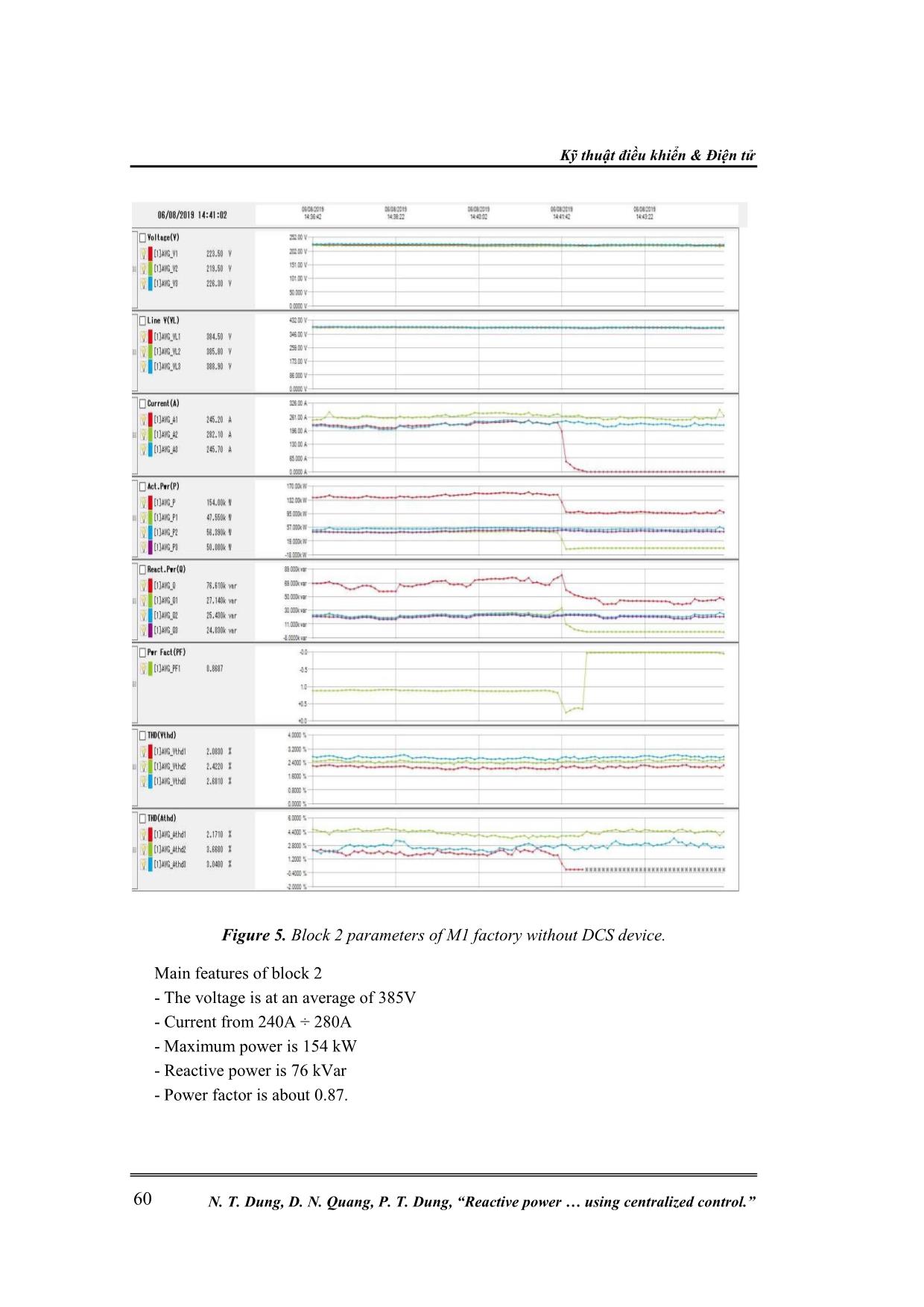
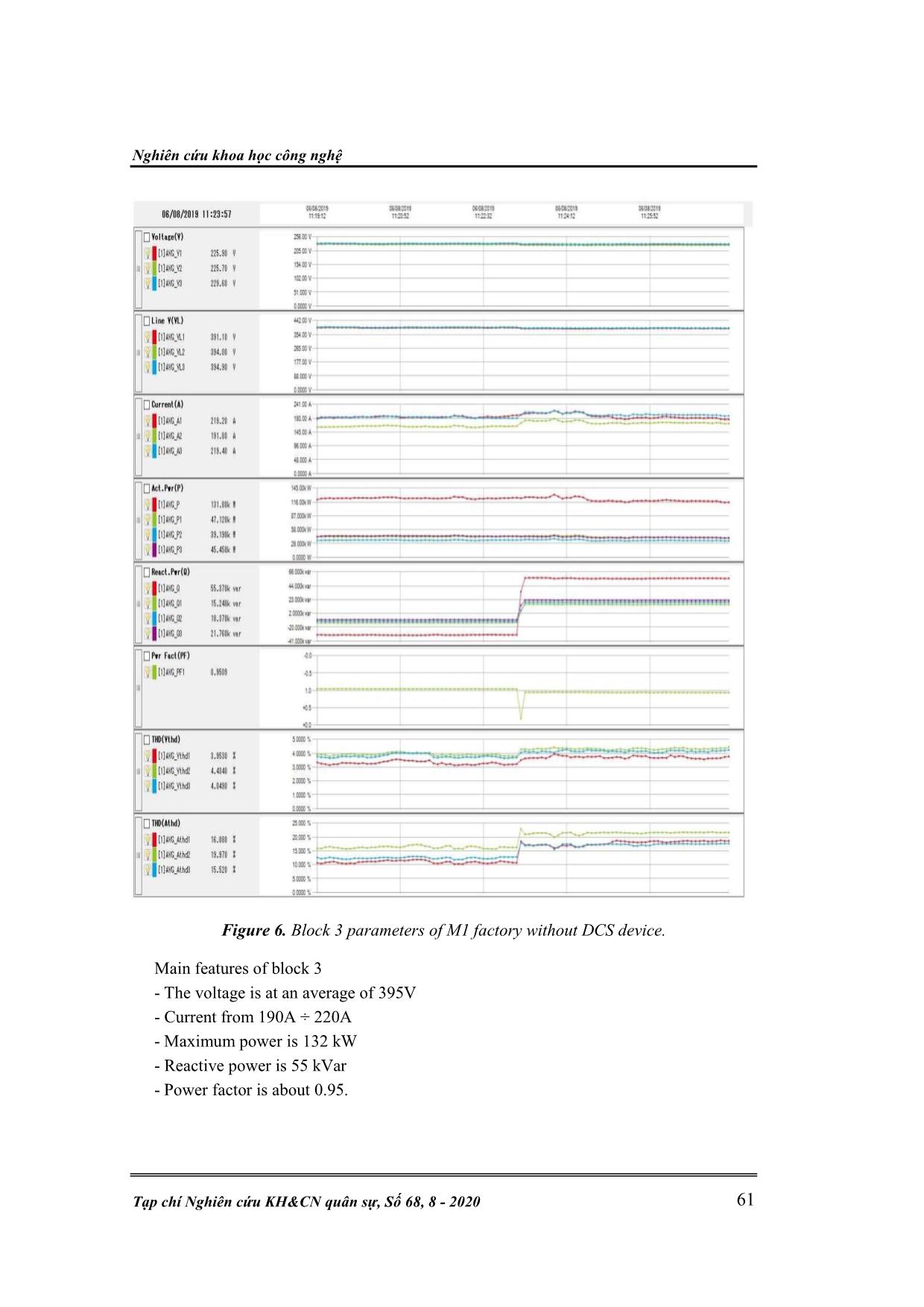
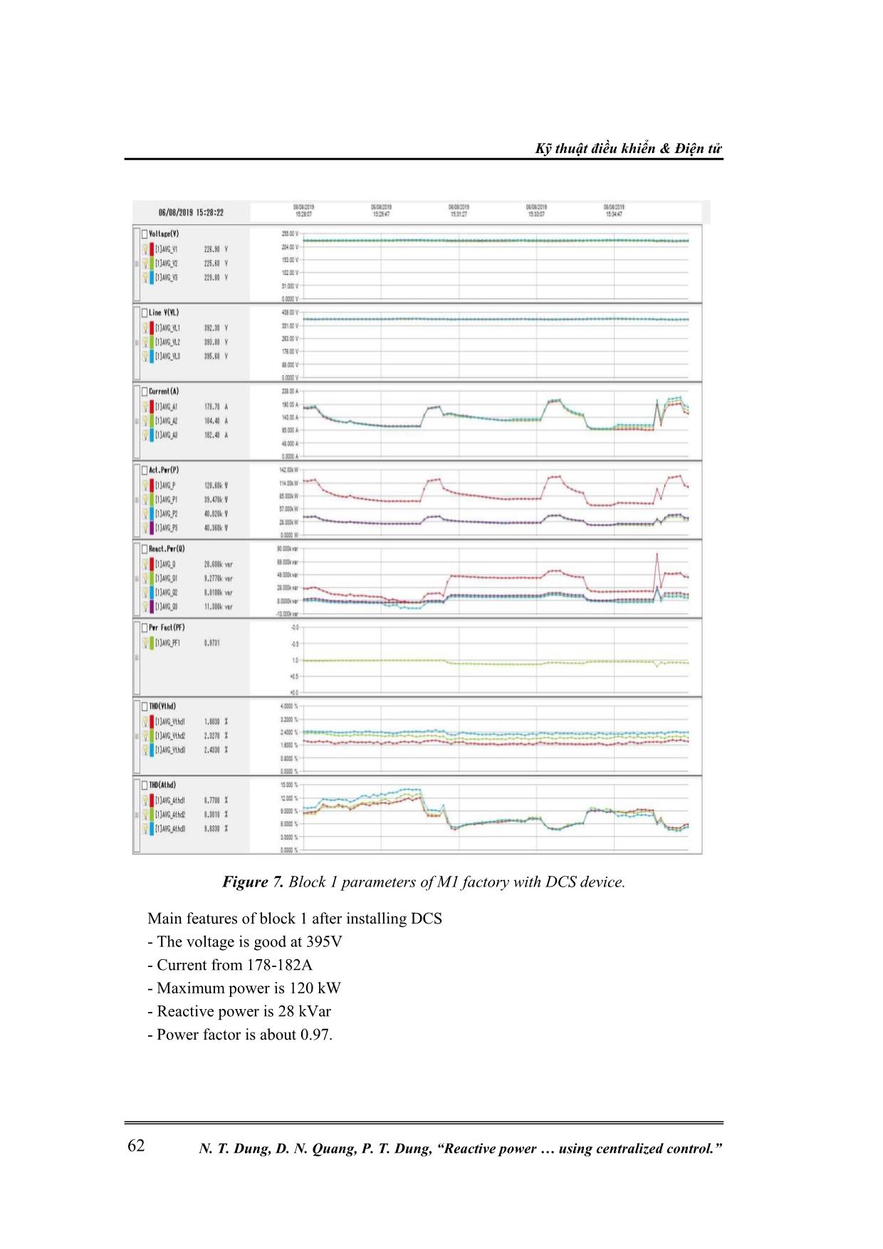
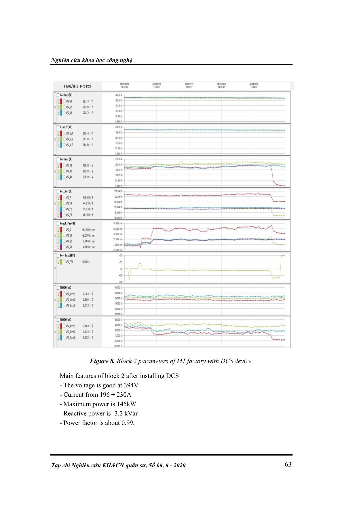
The measured parameters correspond to three load blocks, which are recorded with and
without the installation of the DCS device. They are described in detail in figure 4, figure
5, figure 6, figure 7, figure 8, and figure 9.
Figure 3. Single line diagram of M1 factory.
Nghiên cứu khoa học công nghệ
Tạp chí Nghiên cứu KH&CN quân sự, Số 68, 8 - 2020 59
Figure 4. Block 1 parameters of M1 factory without DCS device.
Main features of block 1
- The voltage is at an average of 390V
- Current from 190A ÷ 220A
- Maximum power is 129 kW
- Reactive power is 51 kVar
- Power factor is between 0.91 and 0.92.
Kỹ thuật điều khiển & Điện tử
N. T. Dung, D. N. Quang, P. T. Dung, “Reactive power  using centralized control.” 60
Figure 5. Block 2 parameters of M1 factory without DCS device.
Main features of block 2
- The voltage is at an average of 385V
- Current from 240A ÷ 280A
- Maximum power is 154 kW
- Reactive power is 76 kVar
- Power factor is about 0.87.
Nghiên cứu khoa học công nghệ
Tạp chí Nghiên cứu KH&CN quân sự, Số 68, 8 - 2020 61
Figure 6. Block 3 parameters of M1 factory without DCS device.
Main features of block 3
- The voltage is at an average of 395V
- Current from 190A ÷ 220A
- Maximum power is 132 kW
- Reactive power is 55 kVar
- Power factor is about 0.95.
Kỹ thuật điều khiển & Điện tử
N. T. Dung, D. N. Quang, P. T. Dung, “Reactive power  using centralized control.” 62
Figure 7. Block 1 parameters of M1 factory with DCS device.
Main features of block 1 after installing DCS
- The voltage is good at 395V
- Current from 178-182A
- Maximum power is 120 kW
- Reactive power is 28 kVar
- Power factor is about 0.97.
Nghiên cứu khoa học công nghệ
Tạp chí Nghiên cứu KH&CN quân sự, Số 68, 8 - 2020 63
Figure 8. Block 2 parameters of M1 factory with DCS device.
Main features of block 2 after installing DCS
- The voltage is good at 394V
- Current from 196 ÷ 230A
- Maximum power is 145kW
- Reactive power is -3.2 kVar
- Power factor is about 0.99.
Kỹ thuật điều khiển & Điện tử
N. T. Dung, D. N. Quang, P. T. Dung, “Reactive power  using centralized control.” 64
Figure 9. Block 3 parameters of M1 factory with DCS device.
Main features of block 3 after installing DCS
- The voltage is good at 400V
- Current from 168 ÷ 202A
- Maximum power is 127kW
- Reactive power is -31 kVar
- Power factor is about 0.96.
The experimental process devided by two phases: with CC and with DCS. The
observing parameters included: block voltages and currents, maximum active and reactive
power, total active power loss on cables and transformer, the power factors.
Nghiên cứu khoa học công nghệ
Tạp chí Nghiên cứu KH&CN quân sự, Số 68, 8 - 2020 65
The main results of using DCS comparing to use CC are obtained as following:
- The voltage in blocks is higher and better (from 395-400 V)
- The maximum active power Pmax is lower 29kW (or 5.67%)
- The total power loss is lower 3.45kW (or 17.8%)
- The block current is lower (from 8 to 18%)
The detail comparison of using CC and DCS is shown on table I.
Table I. The comparison of technical parameters with using CC and DCS.
 Items Regime U (V) I (A) Pmax (kW) P (kW) Q (kvar) PF
Block 1
With CC 390 220 129 3.84 51 0.92
With DCS 395 182 120 3.26 28 0.97
Difference 5.0 -38.0 -9.0 -0.58 -23.0 0.05
Block 2
With CC 385 280 154 7.77 76 0.87
With DCS 394 230 145 5.61 -3 1
Difference 9.0 -50.0 -9.0 -2.16 -79.0 0.13
Block 3
With CC 395 220 132 7.73 55 0.95
With DCS 400 202 127 7.02 -31 0.96
Difference 5.0 -18.0 -5.0 -0.71 -86.0 0.01
As can be seen from table I, with the DCS installation, the power quality is markedly
improved namely: the voltage keeps stable, the current decreases, the power factor
increases, especially the energy consumption and power significantly decrease.
4. CONCLUSION
The distributed voltage regulation system using centralized control is more complex,
however, it has high efficiency comparing to the common centralized control systems.
Furthermore, it helps to adjust voltage better by reducing voltage drop at load. Due to this
advantage, the loads will be more productive, save energy, and prolong the device’s
longevity.
Acknowledgement: This research is funded by the Ministry of Industry and Trade (MOIT)
under grant number 147.2018.ĐT.BO/HĐKHCN. The authors wish to thank Electric Power
University (EPU) for their help during our measurement and experimentations
REFERENCES
[1]. B. Singh, A. Chandra, K. Al-Haddad, Anuradha, and D. P. Kothari, ‘Reactive power
compensation and load balancing in electric power distribution systems’,
International Journal of Electrical Power & Energy Systems, vol. 20, no. 6, pp. 375–
381, Aug. 1998, doi: 10.1016/S0142-0615(98)00008-8.
[2]. D. E. Olivares et al., ‘Trends in Microgrid Control’, IEEE Trans. Smart Grid, vol. 5,
no. 4, pp. 1905–1919, Jul. 2014, doi: 10.1109/TSG.2013.2295514.
[3] .A. Khodaei, ‘Provisional Microgrids’, IEEE Trans. Smart Grid, vol. 6, no. 3, pp.
1107–1115, May 2015, doi: 10.1109/TSG.2014.2358885.
[4]. D. I. Brandao, T. Caldognetto, F. P. Marafao, M. G. Simoes, J. A. Pomilio, and P.
Tenti, ‘Centralized Control of Distributed Single-Phase Inverters Arbitrarily
Kỹ thuật điều khiển & Điện tử
N. T. Dung, D. N. Quang, P. T. Dung, “Reactive power  using centralized control.” 66
Connected to Three-Phase Four-Wire Microgrids’, IEEE Trans. Smart Grid, vol. 8,
no. 1, pp. 437–446, Jan. 2017, doi: 10.1109/TSG.2016.2586744.
[5]. Nguyen Tien Dung, Dinh Ngoc Quang, Bui Anh Tuan, “Giải pháp nâng cao chất
lượng điện áp đối với các thiết bị động cơ công suất lớn,” TC. KH&CN Năng lượng,
số 22, (2020), tr. 48-56.
[6]. Standard, Nema MG 1-12-45.
TÓM TẮT
HỆ THỐNG BÙ CÔNG SUẤT PHẢN KHÁNG
KIỂU PHÂN TÁN ĐIỀU KHIỂN TẬP TRUNG
Bài báo đề xuất thiết bị bù công suất phản kháng dạng phân tán điều khiển tập
trung. Thiết bị này bao gồm hệ thống các tụ bù đặt gần các phụ tải tiêu thụ điện
nhưng chỉ gồm một bộ điều khiển chung duy nhất. Bộ điều khiển, thu thập dữ liệu về
dòng điện, điện áp cũng như công suất của từng nhánh phụ tải điện để từ đó, tiến
hành điều chỉnh trơn công suất phản kháng tổng theo một trình tự ưu tiên, Thiết bị
này sẽ giúp nâng cao chất lượng điện áp tại các phụ tải điện, giảm tổn thất công
suất tác dụng và nâng cao tuổi thọ của các thiết bị điện.
Từ khóa: Bù công suất phản kháng; Thiết bị phân tán điều khiển tập trung; Static Var Compensator (SVC);
Thyristor Control Reactor (TCR).
Received date, 29
th
 May, 2020
Revised manuscript, 17
th
 July, 2020
Published 03
rd
August, 2020
Author affiliations:
1
Electric Power University, Hanoi, Vietnam;
2
Innovative Grid Solutions Company, Hanoi, Vietnam;
3
 Le Quy Don Technical University, Hanoi, Vietnam.
*
Corresponding author: dungnt@epu.edu.vn.
File đính kèm:
 reactive_power_compensation_in_distributed_system_using_cent.pdf

