Evaluation of the Potential for Containment Bypass due to Steam Generator Tube Rupture in VVER-1000/V320 Reactor during Extended SBO sequence using SCDAP/RELAP5 code
A severe accident-induced of a Steam Generator (SG) tube releases radioactivity from
the Reactor Coolant System (RCS) into the SG secondary coolant system from where it may escape
to the environment through the pressure relief valves and an environmental release in this manner is
called “Containment Bypass”. This study aims to evaluate the potential for “Containment Bypass”
in VVER/V320 reactor during extended Station Blackout (SBO) scenarios that challenge the tubes
by primarily involving a natural circulation of superheated steam inside the piping loop and then
induce creep rupture tube failure. Assessments are made of SCDAP/RELAP5 code capabilities for
predicting the plant behavior during an SBO event and estimates are made of the uncertainties
associated with the SCDAP/RELAP5 predictions for key fluid and components condition and for
the SG tube failure margins.
Trang 1
Trang 2
Trang 3
Trang 4
Trang 5
Trang 6
Trang 7
Tóm tắt nội dung tài liệu: Evaluation of the Potential for Containment Bypass due to Steam Generator Tube Rupture in VVER-1000/V320 Reactor during Extended SBO sequence using SCDAP/RELAP5 code
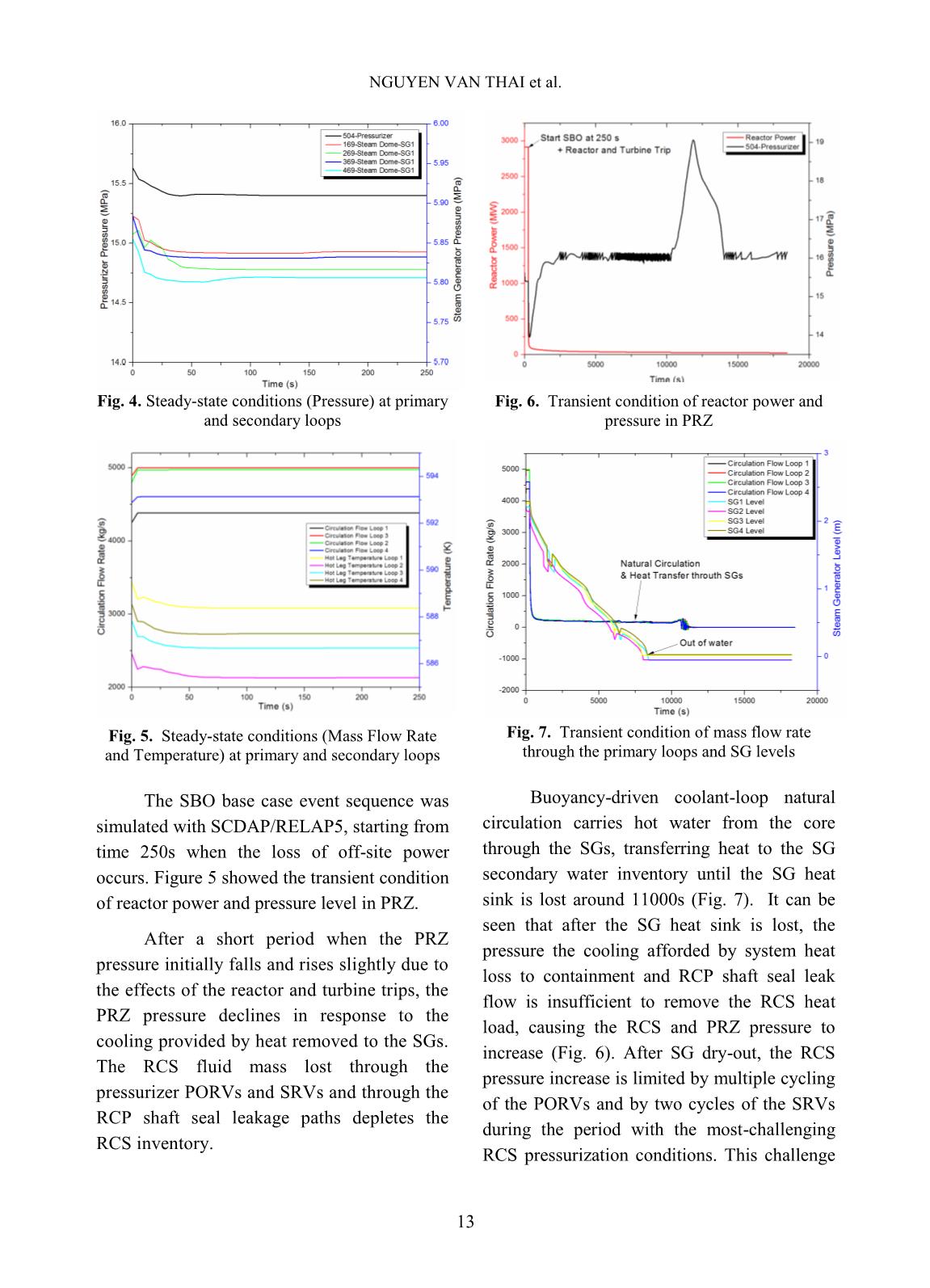
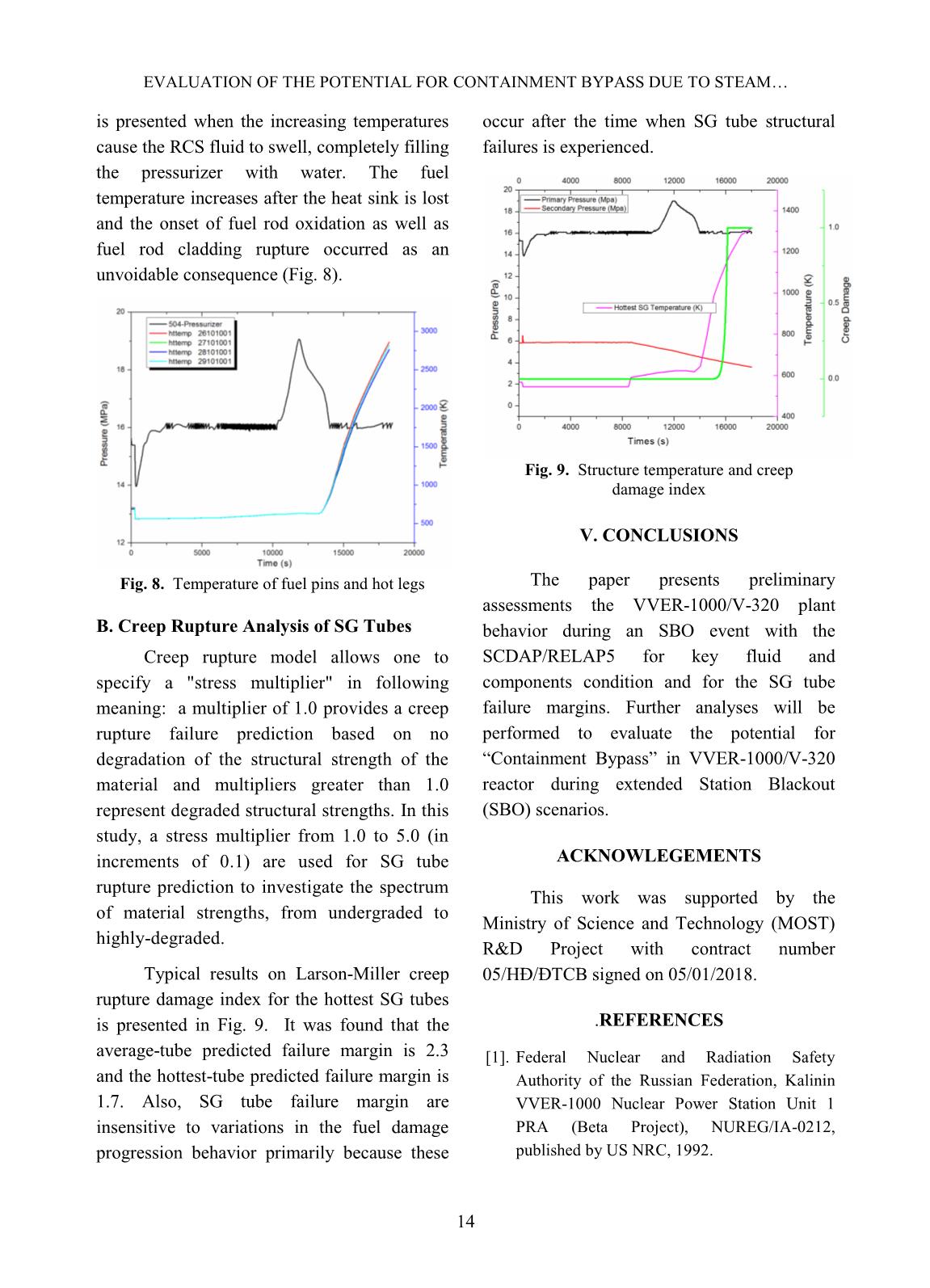
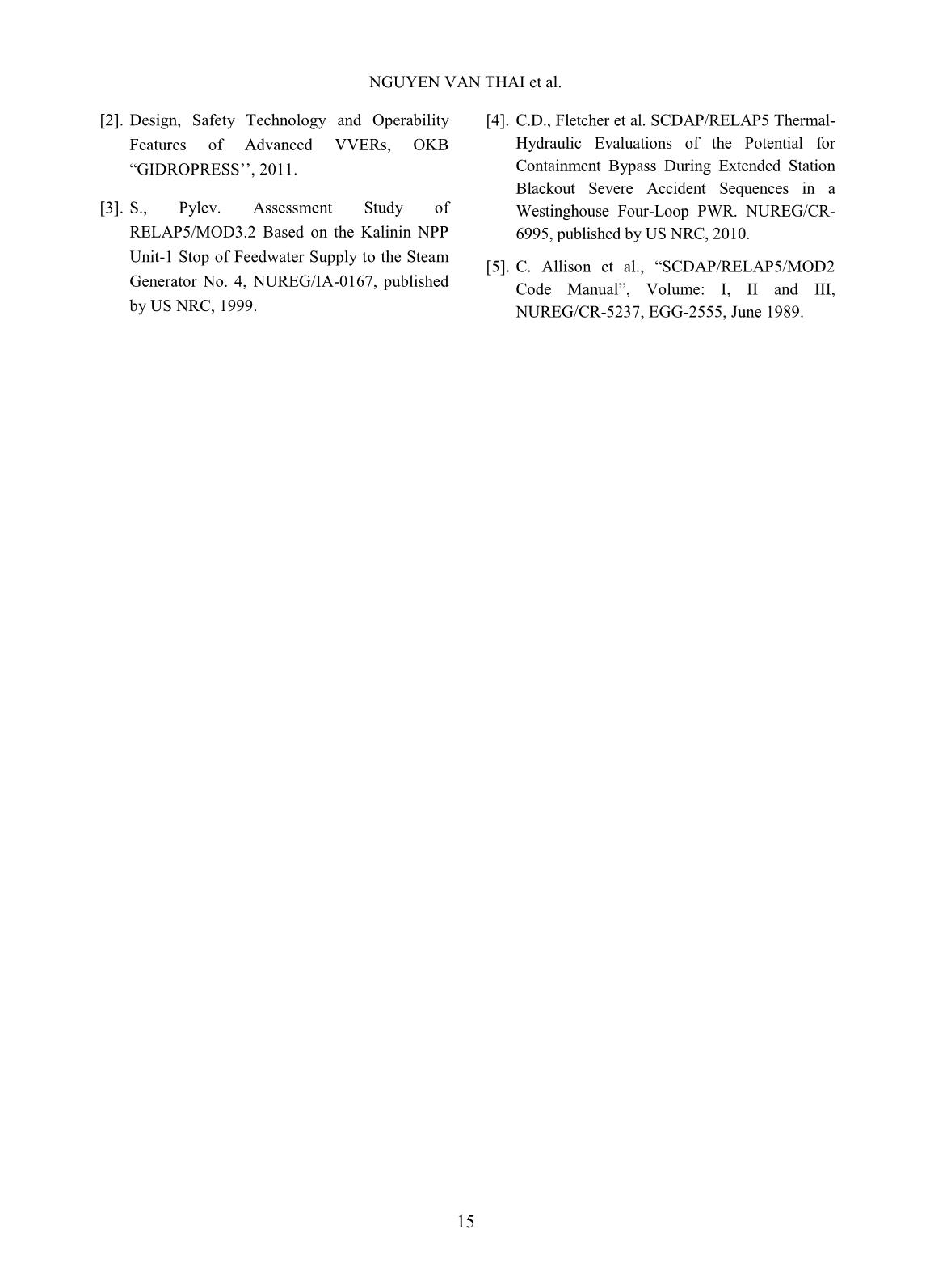
a wide-scope PRA and the PRA model represents the set of accident sequences following the initial events (IEs) up to the end state of each sequence. The reports indicated that the most significant release category for offsite consequences is containment failure as a result of an IE with a leak from the primary to the secondary circuit [1]. In this aspect, steam generator tubes comprise a majority of the reactor coolant system pressure boundary and failure of steam generator tubes prior to the failure of one of other components (hot leg piping, pressurizer surge-line piping, and the reactor vessel) leads to discharge of some fission products into the steam generator secondary system from where they may be discharged to the environment through the pressure-relief valves. This sequence is potentially more risk-significant since it involves a containment bypass scenario. The relative timing of these structural failures therefore affects the event sequence and whether the containment is bypassed. This paper present thermal-hydraulic evaluations of VVER-1000/V-320 during extended SBO event using the SCDAP/RELAP5 systems analysis code. In general, the design features of VVER-1000/V- 338 are similar to the standard VVER-1000/V- 320, excepted of the main circulation loops EVALUATION OF THE POTENTIAL FOR CONTAINMENT BYPASS DUE TO STEAM 10 configuration which is equipped with main gate valves on the cold and hot legs (CLs and HLs) [2]. The potential for “Containment Bypass” is associated with natural circulation of superheated steam inside the piping loop that might induce creep rupture tube failure. SCDAP/RELAP5 predictions provide key fluid and components condition for estimation of the SG tube failure margins. II. DESCRIPTIONS OF ACCIDENT SCENARIO AND PLANT BEHAVIOR The low-probability SBO base case accident event scenario results in a severe accident because none of the systems that normally provide core cooling are assumed to be operable nor is any alternate equipment (e.g., security-related mitigation methods) assumed to be available [4]. The accident event is initiated by a loss of off-site alternating current (AC) power, which immediately results in reactor and turbine trips and the coast-down of the four reactor coolant pumps (RCPs). Also, assumptions are made as follows: The diesel-electric generators fail to start and all AC power sources are lost; Letdown flow is isolated and the pressurizer level control and RCP seal injection functions of the charging system are lost; The high-pressure and low-pressure safety injection systems are unavailable as a result of the AC power loss; The accumulator systems (four HAs) are available for injecting coolant into the cold legs should the RCS pressure fall below the initial accumulator pressure, 5.9 MPa; The main feedwater (MFW) flow stops and the motor-driven auxiliary feedwater (MDAFW) system is unavailable as a result of the AC power loss; The turbine-driven auxiliary feedwater (TDAFW) system is assumed to independently fail, so no MFW or auxiliary feedwater (AFW) system is available; A station battery life of four hours is assumed; after that time all automatic and operator control of the pressurizer PORVs and SG secondary system PORVs is lost; During the initial portion of the accident scenario, buoyancy-driven coolant-loop natural circulation carries hot water from the core through the SGs, transferring heat to the SG secondary water inventory. The SG water inventory is boiled and the steam is released through the SG PORVs. The secondary water inventory declines and is eventually fully depleted since the MFW and AFW systems are not operative. After that time, the core decay power heats and swells the RCS water, increasing its temperature and pressure. The basic physical processes during this regard the transport of hot steam from the core outward into the other regions of the reactor vessel (RV) and coolant loops. Two coolant loop natural circulation flow patterns that may be encountered subsequent to the uncovering and heat-up of the reactor core, based upon whether or not the loop seals (the cold leg piping connecting the outlets of the SGs to the inlets of the RCPs) remain liquid-plugged. If liquid is cleared from a loop seal (along with the region of the RV lower plenum that extends above the bottom of the core barrel, the "downcomer skirt"), hot steam is transported from the core through the HL, SG tubes and cold legs in the normal direction of flow (i.e., that seen during plant operation). This flow pattern transports the hot steam directly (without benefit of mixing) through all of the SG tubes, leading to SG tube failure NGUYEN VAN THAI et al. 11 prior to HL or pressurizer surge line failure. However, if a loop seal remains liquid- plugged, the more complex flow pattern develops instead. Hot steam is transported through the upper portion of the HL cross section to the SG inlet plenum, where it is mixed with cooler steam emanating from circulations set up within the SGs, with some of the tubes flowing in the normal direction and the remaining tubes flowing in the reverse direction. The mixing process within the SG inlet plenum determines the temperatures of the steam entering the SG tubes and the steam that is returned to the RV through the lower portion of the HL cross section. Fluid mixing in the SG inlet plenum buffers the entry of hot steam into the SG tubes, thus delaying SG tube failure and making it more likely that some other component (HL, pressurizer surge line or RV) will be the first to fail. The issues of primary interest for containment bypass are: (1) do the loop seals in all coolant loops remain liquid plugged and if so (2) does the fluid mixing in the SG inlet plenum sufficiently slow the SG tube heat-up process so that the HL, pressurizer surge line or RV will fail prior to a SG tube? [4]. The analyses in this paper address these issues. Fig. 1. RCS Layout of VVER-100/V-320 [3] 471 472 473 478 479 461 462 463 464 465 466 474 475 476 171 172 173 178 179 161 162 163 164 165 166 174 175 176 15-1714-16 18-20 19-21 22-24 23-25 26 28 29 27 1 2 3 4 5 6 7 8 9 30 32 33 31 34 4 3 2 1 35 1 1 37-4036 6 41-44 6 7 8 45-48 51-52 63-64 3-4 54 56 7-8 6 5 4 3 2 1 6 5 4 3 2 1 10-129-11 61-62 1-2 5-6 425 424 423 422 421 400 1 2 3 4 504 506 502 402 410 411 412 413 414 415 416 436 435 434 433 432 431 430 11 444 441442 9 440 125 124 123 122 121 100 1234 102 110 111 112 113 114 115 116136 135 134 133 132 131 130 11144141 142 9 140 167 168 169 Separator Volume above perforated sheets Steam dome 177 Volume between tube bundles and perforated sheets 150 152 Volume between tube bundles and perforated sheets 450 452 467 468 469 Separator Volume above perforated sheets Steam dome 477 480 482484 490 492 180 182 184 190 192 186 486286 386 194 196 TURBINE MSIV 187 MSIV 287 MSIV 387 MSIV 487 1 508 511 PORV 49-50 ACC ACC ACCACC JNG50 086 JNG60 087 JNG70 088 JNG80 089 REG Valve 185 REG Valve 285 REG Valve 385 REG Valve 485 BRU-A1 BRU-In1 BRU-A1 BRU-In1 191 189 489 491 Fig. 2. Nodalization scheme of VVER-1000/V-320 Plant EVALUATION OF THE POTENTIAL FOR CONTAINMENT BYPASS DUE TO STEAM 12 III. PLANT NODALIZATION AND PARAMETERS SETUP WITH SCDAP/RELAP5 The SCDAP/RELAP5 computer code calculates the overall RCS thermal-hydraulic response for severe accident situations that include core damage progression and RV heat- up and damage. The computer code is the result of a merging of the RELAP5 and SCDAP computer codes. Prediction of structural failure are made based on the structure configuration, its material properties and the fluid conditions that are locally present. The code also includes models for calculating the creepture failure of structural components and these are used to predict failure time for the hot legs, pressurizer surge line, and SG tubes [5]. The SCDAP/RELAP5 VVER- 1000/V320 plant model represents the fluid volumes and structures in the core, RV and primary and secondary coolant system regions in the plant as shown in Fig 1. The nodalization diagrams for the final SCDAP/RELAP5 VVER-1000/V-320 four-loop plant model are provided in Fig. 2. In this work, creep rupture failure calculations are performed for the hot average SG tubes in which pressure and temperature conditions of fluid and heat structures in four SGs are used as inputs for the analyses. A parameter that measure creep damage is calculated each time step for each structure being monitored for creep rupture by following equation: tt t tDttD r cc (1) Where tDc is creep damage at problem time t, t is time step at current problem time and ttr is time required for the structure to fail by creep rupture at current state of temperature and stress. If the value of Dc is zero, the structure has not experienced any creep damage. If the value is one, the structure has failed due to creep damage. Two different theories (Larson Miller and Manson-Haferd) are applied in SCDAP/RELAP5 which are dependent upon the structural materials and the range of stress and summarized in Table I. Table I. Equations for the time to creep rupture [5] Since SG tubes are made from heat- resistant steel (08X18H10T) which is similar to heat-resistant Stainless Steel, equations for creep rupture time of 316 Stainless Steel in Table i are selected in this study. Estimated stress in SG tubes (cylindrical shaped structure) is calculated as follows: io ooii rr rPrP )( (2) Fig. 3. Model ofSG ubes IV. RESULTS AND DISCUSSION A. Plant behaviors The SCDAP/RELAP5 plant model was run to a steady solution. The plant model using the nodalization scheme to establish full-power steady-state conditions from which the SBO transient accident sequence is initiated (Figures.4&5). NGUYEN VAN THAI et al. 13 Fig. 4. Steady-state conditions (Pressure) at primary and secondary loops Fig. 5. Steady-state conditions (Mass Flow Rate and Temperature) at primary and secondary loops The SBO base case event sequence was simulated with SCDAP/RELAP5, starting from time 250s when the loss of off-site power occurs. Figure 5 showed the transient condition of reactor power and pressure level in PRZ. After a short period when the PRZ pressure initially falls and rises slightly due to the effects of the reactor and turbine trips, the PRZ pressure declines in response to the cooling provided by heat removed to the SGs. The RCS fluid mass lost through the pressurizer PORVs and SRVs and through the RCP shaft seal leakage paths depletes the RCS inventory. Fig. 6. Transient condition of reactor power and pressure in PRZ Fig. 7. Transient condition of mass flow rate through the primary loops and SG levels Buoyancy-driven coolant-loop natural circulation carries hot water from the core through the SGs, transferring heat to the SG secondary water inventory until the SG heat sink is lost around 11000s (Fig. 7). It can be seen that after the SG heat sink is lost, the pressure the cooling afforded by system heat loss to containment and RCP shaft seal leak flow is insufficient to remove the RCS heat load, causing the RCS and PRZ pressure to increase (Fig. 6). After SG dry-out, the RCS pressure increase is limited by multiple cycling of the PORVs and by two cycles of the SRVs during the period with the most-challenging RCS pressurization conditions. This challenge EVALUATION OF THE POTENTIAL FOR CONTAINMENT BYPASS DUE TO STEAM 14 is presented when the increasing temperatures cause the RCS fluid to swell, completely filling the pressurizer with water. The fuel temperature increases after the heat sink is lost and the onset of fuel rod oxidation as well as fuel rod cladding rupture occurred as an unvoidable consequence (Fig. 8). Fig. 8. Temperature of fuel pins and hot legs B. Creep Rupture Analysis of SG Tubes Creep rupture model allows one to specify a "stress multiplier" in following meaning: a multiplier of 1.0 provides a creep rupture failure prediction based on no degradation of the structural strength of the material and multipliers greater than 1.0 represent degraded structural strengths. In this study, a stress multiplier from 1.0 to 5.0 (in increments of 0.1) are used for SG tube rupture prediction to investigate the spectrum of material strengths, from undergraded to highly-degraded. Typical results on Larson-Miller creep rupture damage index for the hottest SG tubes is presented in Fig. 9. It was found that the average-tube predicted failure margin is 2.3 and the hottest-tube predicted failure margin is 1.7. Also, SG tube failure margin are insensitive to variations in the fuel damage progression behavior primarily because these occur after the time when SG tube structural failures is experienced. Fig. 9. Structure temperature and creep damage index V. CONCLUSIONS The paper presents preliminary assessments the VVER-1000/V-320 plant behavior during an SBO event with the SCDAP/RELAP5 for key fluid and components condition and for the SG tube failure margins. Further analyses will be performed to evaluate the potential for “Containment Bypass” in VVER-1000/V-320 reactor during extended Station Blackout (SBO) scenarios. ACKNOWLEGEMENTS This work was supported by the Ministry of Science and Technology (MOST) R&D Project with contract number 05/HĐ/ĐTCB signed on 05/01/2018. .REFERENCES [1]. Federal Nuclear and Radiation Safety Authority of the Russian Federation, Kalinin VVER-1000 Nuclear Power Station Unit 1 PRA (Beta Project), NUREG/IA-0212, published by US NRC, 1992. NGUYEN VAN THAI et al. 15 [2]. Design, Safety Technology and Operability Features of Advanced VVERs, OKB “GIDROPRESS’’, 2011. [3]. S., Pylev. Assessment Study of RELAP5/MOD3.2 Based on the Kalinin NPP Unit-1 Stop of Feedwater Supply to the Steam Generator No. 4, NUREG/IA-0167, published by US NRC, 1999. [4]. C.D., Fletcher et al. SCDAP/RELAP5 Thermal- Hydraulic Evaluations of the Potential for Containment Bypass During Extended Station Blackout Severe Accident Sequences in a Westinghouse Four-Loop PWR. NUREG/CR- 6995, published by US NRC, 2010. [5]. C. Allison et al., “SCDAP/RELAP5/MOD2 Code Manual”, Volume: I, II and III, NUREG/CR-5237, EGG-2555, June 1989.
File đính kèm:
 evaluation_of_the_potential_for_containment_bypass_due_to_st.pdf

