Design analyses for full core conversion of the dalat nuclear research reactor
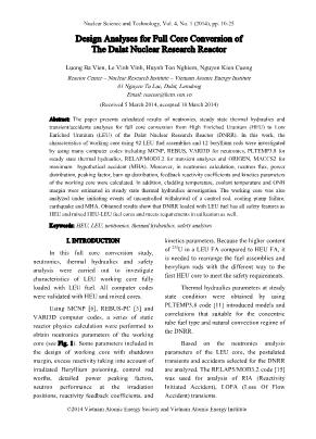
The paper presents calculated results of neutronics, steady state thermal hydraulics and
transient/accidents analyses for full core conversion from High Enriched Uranium (HEU) to Low
Enriched Uranium (LEU) of the Dalat Nuclear Research Reactor (DNRR). In this work, the
characteristics of working core using 92 LEU fuel assemblies and 12 beryllium rods were investigated
by using many computer codes including MCNP, REBUS, VARI3D for neutronics, PLTEMP3.8 for
steady state thermal hydraulics, RELAP/MOD3.2 for transient analyses and ORIGEN, MACCS2 for
maximum hypothetical accident (MHA). Moreover, in neutronics calculation, neutron flux, power
distribution, peaking factor, burn up distribution, feedback reactivity coefficients and kinetics parameters
of the working core were calculated. In addition, cladding temperature, coolant temperature and ONB
margin were estimated in steady state thermal hydraulics investigation. The working core was also
analyzed under initiating events of uncontrolled withdrawal of a control rod, cooling pump failure,
earthquake and MHA. Obtained results show that DNRR loaded with LEU fuel has all safety features as
HEU and mixed HEU-LEU fuel cores and meets requirements in utilization as well.
Trang 1
Trang 2
Trang 3
Trang 4
Trang 5
Trang 6
Trang 7
Trang 8
Trang 9
Trang 10
Tải về để xem bản đầy đủ
Tóm tắt nội dung tài liệu: Design analyses for full core conversion of the dalat nuclear research reactor
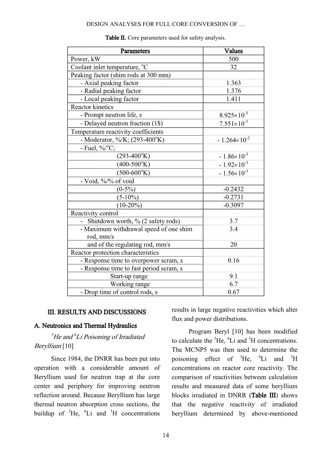
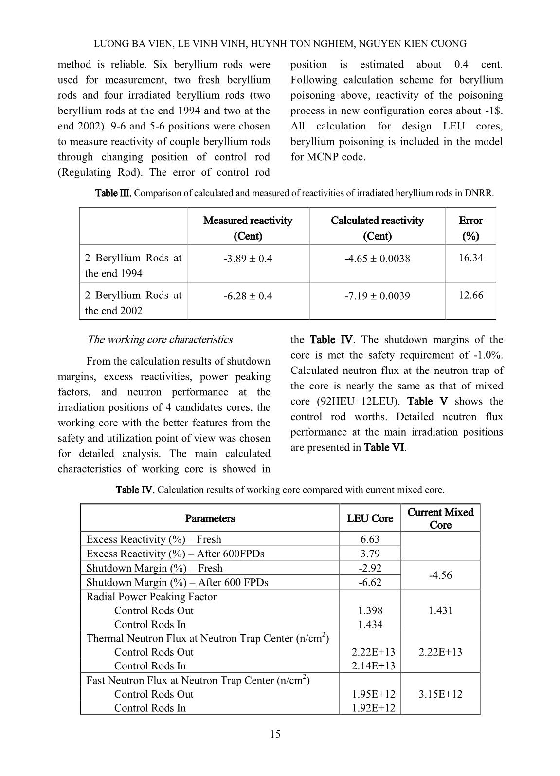
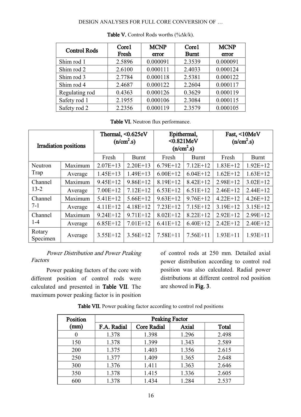
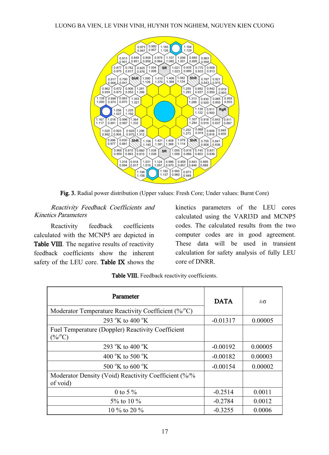
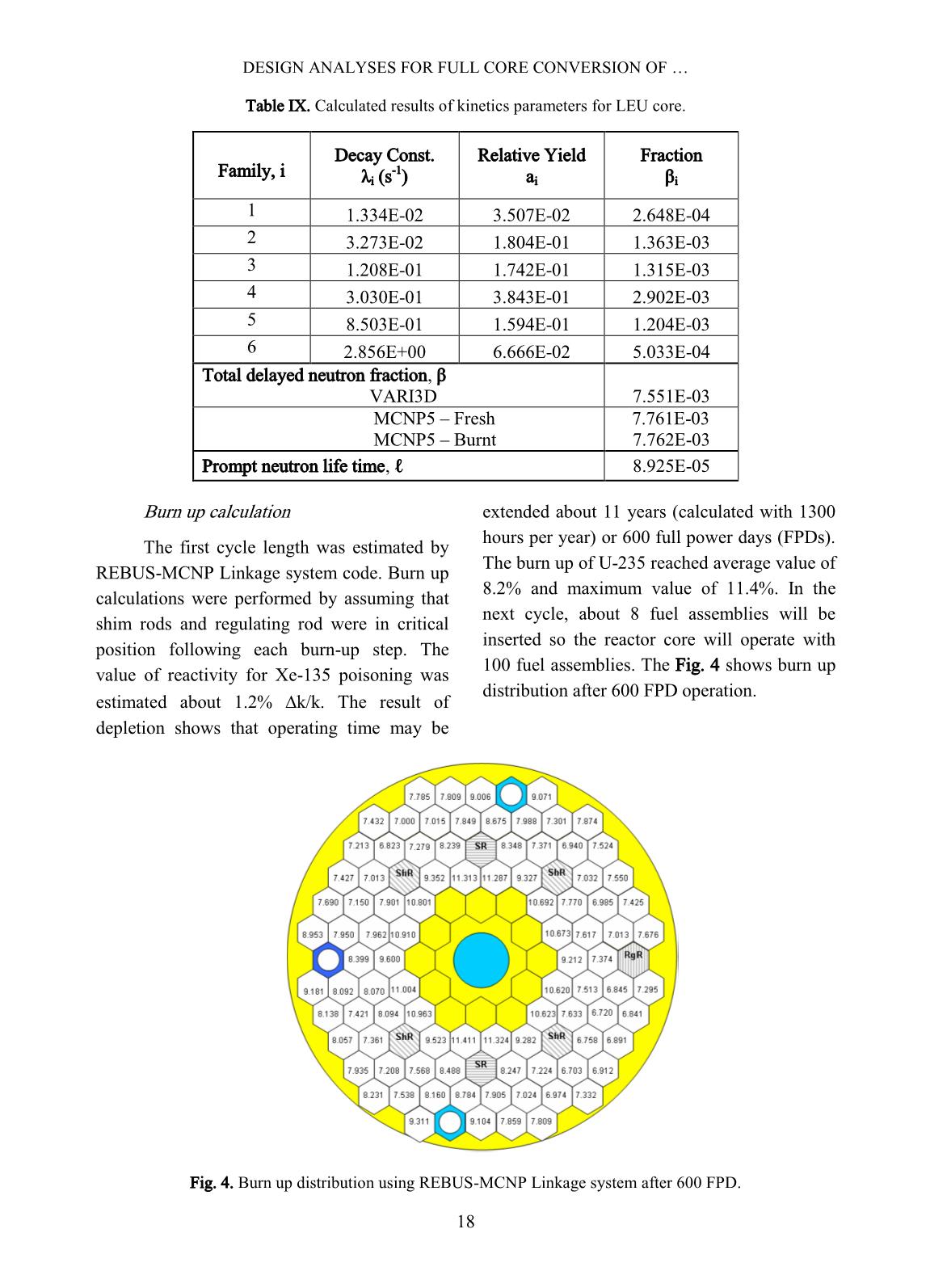
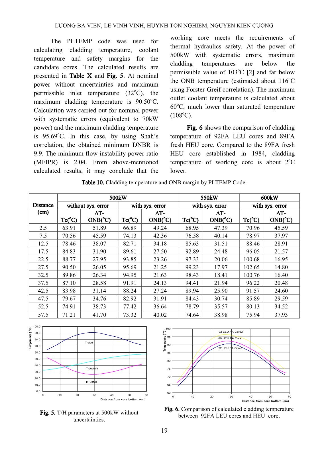
0.9 1.0 0 2 4 6 8 10 12 14 16 18 20 Time (s) P o w e r (M W ) 0 2 4 6 8 10 12 14 16 18 20 D N B R Period scram Overpower scram with set point 110% FP DNBR 40 50 60 70 80 90 100 110 120 0 2 4 6 8 10 12 14 16 18 20 Time (s) T e m p e ra tu re ( o C ) Period scram Overpower scram with set point 110% FP Fig. 7. Reactor power and cladding temperature transient of one shim rod withdrawal from a stable operation of 100%FP. Cooling pump failure In the event of in-service primary or secondary cooling pumps stopped working, the reactor is automatically shutdown by an abnormal technological signal on low flow rate (the setpoint is 40 m 3 /h for the primary flow, and 70 m 3 /h for the secondary flow). The residual heat after shutdown is about 6% FP (30 kW) in maximum and the natural convection process can itself assure the good cooling of the core. If the reactor is purposely maintained at full power operation, failure of cooling pumps leads to loss of heat removal from the pool water, and thus gradually increases of the pool water temperature. The results show that the clad temperature reaches the maximum allowable operating clad temperature of 103 o C at about 55 min; i.e. the reactor could continue its operation for 55 minutes within the envelope of the limiting conditions of operation. The results also show that even at the end of the simulation (7000 s) the clad temperature has been well below that of the acceptance criterion for anticipated operational occurrences. Earthquake The postulated event of an earthquake of intensity grade VI is assumed to occur while the reactor is at full power. Owing to the measures undertaken in design and construction, the removal of all control rods would not exceed 10 mm and insert a step positive reactivity estimated of 0.3$. With this reactivity insertion, the scram set-point of reactor overpower is attained almost instantaneously. If the reactor scram is initiated by overpower signal with a delay of 0.16 sec, the fuel surface temperature increases slightly before decreases with the power, the residual heat after shutdown is sufficiently removed from the fuel by natural convection of pool water without considerable increase of the temperature. Fig. 8 shows the analyzing results of the earthquake event assuming the protection system fails to shutdown the reactor, and Because of the loss of offsite power due to the earthquake, the primary and secondary pumps stop operating. In this case, the reactor power increases to the max value of 1.525 MW after 200 seconds from the initiation of this event. The reactor power then rapidly decreases because the significant increasing of core water temperature so that the positive reactivity insertion is overtaken by the negative reactivity feedback (about -0.44$). The reactor is then kept at subcritical state. The cladding temperature reaches a maximum value of 118.2 o C, then decreases with no DESIGN ANALYSES FOR FULL CORE CONVERSION OF 11 22 significant overheating of the fuel. The maximum outlet water reaches 89 o C and gradually decreases to a value at about 60 o C, which is still far below the saturation temperature. The minimum DNBR of 4.79 is much higher than the acceptance value. In case the cooling pumps remain working after the earthquake event (very unlikely); the peak power reaches 1.57 MW within 300 seconds and decreases due to negative temperature feedback to a stable value of about 1.12 MW. The cladding temperature reaches to a maximum value of 118.38 o C then gradually decreases to a stable value of 115 o C without nucleate boiling. The maximum temperature of outlet water is 89 o C at the peak power then decreases and stabilizes at about 82 o C, well below the saturation point. The minimum DNBR in this case estimated about 4.74 is still far from the acceptance criterion. Fig. 9. Power and Temperature responses to earthquake event while cooling pumps are stopped functioning. Fuel cladding failure (MHA) For the derivation of source term of this event, it is assumed that no core melting occurs but cladding rupture of one fuel assembly is involved. It is also assumed that the damaged fuel assembly is irradiated at the maximum neutron flux position in the core and the fuel damage occurs immediately at the end of operating cycle of 100 hrs with no decay. From the damaged fuel assembly, 100% of noble gases (Xe, Kr), 25% halogens (I), and 1% of other radionuclides (Cs, Te) [21] are released directly to the reactor building with the assumption of no retention of volatile fission products in the pool water. During the accident evolution, the emergency ventilation system is not in place, the normal ventilation system V1 is in operation but HEPA filter with 95% efficiency is not available, and there are no decay and deposition of radionuclides within the reactor building. The evaluation of dose to a member of the public is calculated by code MACCS2 version 1.13.1, using the following assumptions: (1) The radionuclides are released to the environment through the 40 m stack; (2) The Gaussian plume model is used to calculate air concentration of radioactivity; (3) Tadmor and Gur parameterization is used for this analysis; (4) No building in the vicinity (an open area release), plume rise mechanics only due to momentum rise (non-buoyant plume) and no wet deposition are assumed; (5) The dry deposition velocity is assumed to be 0.01 m/s, which corresponds to a particle with an aerodynamic equivalent diameter of 2 m to 4 m (for unfiltered particulate releases) [15]; (6) 0.0 0.2 0.4 0.6 0.8 1.0 1.2 1.4 1.6 0 500 1000 1500 2000 2500 3000 3500 4000 4500 5000 Time (s) P o w e r (M W ) 0 2 4 6 8 10 12 14 16 D N B R DNBR Power 30 40 50 60 70 80 90 100 110 120 0 500 1000 1500 2000 2500 3000 3500 4000 4500 5000 Time (s) T e m p e ra tu te ( o C ) Max. Cladding Temperature Max. Water Temperature at Outlet Water Temperature at Inlet LUONG BA VIEN, LE VINH VINH, HUYNH TON NGHIEM, NGUYEN KIEN CUONG 11 23 Surface roughness length is specified as 50 cm; (7) Mixing layer height is assumed to be 500 m (see Table 36 in Appendix VII of Ref. 21); (8) The breathing rate is 3.3x10 -4 m 3 /s; (9) No shielding and sheltering are assumed; (10) Doses at each downwind distance are calculated for one year after the arrival of the plume (11). The environmental release is assumed to begin at the start of the weather conditions: Pasquill class D2.0 (most frequent stability class and most frequent wind speed). The effective equivalent doses, including cloudshine dose, inhalation dose and groundshine dose, as a function of the distance from the source are shown in Table XII and Fig. 10. It is seen that radiation exposure to the general public with the maximum effective dose of 0.64 mSv/year at distance from 400 m to 500 m from the stack. This value is lower than the annual dose limit of 1.0 mSv specified for the public [22]. Table XII. The annual effective dose to the public vs distance for the MHA. Distance (m) Effective Dose (mSv) Distance (m) Effective Dose (mSv) 50 4.80E-02 1100 3.18E-01 150 1.43E-01 1300 2.59E-01 250 4.95E-01 1500 2.16E-01 350 6.42E-01 1700 1.83E-01 450 6.44E-01 1900 1.57E-01 550 5.94E-01 2250 1.23E-01 650 5.33E-01 2750 9.14E-02 750 4.74E-01 3250 7.08E-02 850 4.21E-01 3750 5.66E-02 950 3.75E-01 4250 4.64E-02 Fig. 10. The annual effective dose to the public in MHA event within 5 km. 0.00E+00 1.00E-01 2.00E-01 3.00E-01 4.00E-01 5.00E-01 6.00E-01 7.00E-01 0 500 1000 1500 2000 2500 3000 3500 4000 4500 5000 Downwind Distance, m E ff ec ti v e E q u iv a le n t D o se , m S v DESIGN ANALYSES FOR FULL CORE CONVERSION OF 24 IV. CONCLUSIONS Neutronics, steady-state thermal- hydraulic and transient/accidents analyses for Dalat Nuclear Research Reactor show that with a slight change in arrangement of Be rods, the main features of 92 LEU WWR-M2 FA cores are equivalent to those of HEU and current mixed fuel cores. The negative values of reactivity feedback coefficients show the inherent safety feature and shutdown margin of both candidate cores meets the safety required value of -1% k/k. The working core with 92 fresh LEU fuel assemblies can be operated for 600FPDs or about 11 years based on the current operating schedule without shuffling. The neutron fluxes at the irradiation positions are not much different from those of the current mixed fuel core. In thermal hydraulics aspect, the requirement of thermal-hydraulic safety margin for two candidate cores in normal operational condition is satisfied. The calculated maximum cladding temperature in operational condition is below the permissible value of 103 o C. In transient/accidents aspect, some postulated initiating events and accident related to the conversion of the DNRR to full LEU core were selected and analyzed. Based on the calculated results, conclusions might be withdrawn as following: - The excess reactivity insertions when inadvertent withdrawals of control rod from start-up or nominal power operation are prevented by safety settings to initiate the reactor scram at overpower and fast period. None of these initiators would lead to the ONB and DNB, ensuring the integrity of the fuel cladding. The residual heat after shutdown is sufficiently removed from the fuel by natural convection of pool water. - If one of the cooling pumps stopped working, the reactor is automatically shutdown by a scram signal on low flow rate. The decay heat is removed from the fuel by natural convection of pool water. In this event, if the reactor was purposely maintained at full power, it could be safely operated for 55 minutes when maximum cladding temperature is still lower than the permissible value of 103 o C. - The postulated earthquake event of MSK intensity grade VI would cause a step reactivity insertion of 0.3$. Even if the reactor fails to be scrammed, this positive reactivity can be covered by negative temperature feedback if the cooling pumps are stopped simultaneously, keeping the reactor sub-critical. In case the cooling pumps continue operating after earthquake event, the negative temperature feedbacks act to bring the reactor power to a stable level of about 1.12 MW without nucleate boiling. The minimum DNBR is much higher than the acceptance criterion of 1.5. - The maximum hypothetical accident assumes 100% of noble gases (Xe, Kr), 25% halogens (I), and 1% of other radio-nuclides (Cs, Te) in a most power fuel assembly after a long run are released into the environment through 40m high stack. This event is considered to be very unlikely to occur for the DNRR. Even so, it would not cause undue radiological risk to the environment or the public. ACKNOWLEADGMENTS The authors would like to express their gratitude to experts from the Reduced Enrichment for Research and Test Reactors (RERTR) program of Argonne National Laboratory for financial support as well as very useful discussions during design calculation of full core conversion for the Dalat Nuclear Research Reactor. LUONG BA VIEN, LE VINH VINH, HUYNH TON NGHIEM, NGUYEN KIEN CUONG 11 25 REFERENCES [1] Safety Analysis Report for the Dalat Nuclear Research Reactor, (2003). [2] VVR-M2 and VVR-M5 Fuel Assemblies- Operation Manual, 0001.04.00.000 PЭ, (2006). [3] Report on the 7th Core Loading for the Dalat Nuclear Research Reactor, NRI, Dalat, (in Vietnamese), (2009). [4] J.R. Deen, W.L. Woodruff, C.I. Costescu, and L. S. Leopando, “WIMS-ANL User Manual Rev. 5”, ANL/RERTR/TM-99-07, Argonne National Laboratory, (February 2003). [5] P. Olson, “A Users Guide for the REBUS-PC Code, Version 1.4,” ANL/RERTR/TM02-32, (December 21, 2001). [6] J. F. Briesmeister, Ed., “MCNP – A General Monte Carlo N-Particle Transport Code, Version 4C”, LA-13709-M (April 2000). [7] John G. Stevens, “The REBUS-MCNP Linkage”, Argonne National Laboratory, (2007). [8] N.A. Hanan, J.R. Deen, J.E. Matos, “Analyses for Inserting Fresh LEU Fuel Assemblies Instead of Fresh Fuel Assemblies in the DNRR in Vietnam, 2004 International Meeting on RERTR, Vienna, (2004). [9] V. V. Le, T. N. Huynh, B. V. Luong, V. L. Pham, J. R. Liaw, J. Matos, “Comparative Analyses for Loading LEU Instead of HEU Fuel Assemblies in the DNRR”, RERTR Int’l Meeting, Boston, (2005). [10] Teresa Kulikowska et al., Raport IAE-40/A, (1999). [11] Arne P. Olson, M. Kalimullah, “A users guide to the PLTEMP/ANL V3.8 Code”, ANL/RERTR, Argonne National Laboratory, (June, 2009). [12] Le Vinh Vinh, Huynh Ton Nghiem and Nguyen Kien Cuong, “Preliminary results of full core conversion from HEU to LEU fuel of the Dalat Nuclear Research Reactor”, RERTR Int’l Meeting, Beijing, (2009). [13] Technical Design for Reconstruction and Enlargement of the Dalat Nuclear Research Reactor - Volume 3. State Design Institute, USSR State Committee for the Utilization of Atomic Energy, Moscow, (in Russian) (1979). [14] Additional Physics and Thermal-Hydraulic Data for Reactor IVV-9, State Design Institute, USSR State Committee for the Utilization of Atomic Energy, Moscow, (in Russian) (1980). [15] RELAP5/MOD3 Code Manual, SCIENTECH, Inc. Rockville, Maryland, (1999). [16] W. L. Woodruff, et al., A comparison of the PARET/ANL and RELAP5/MOD3 Codes for the Analysis of IAEA Benchmark Transients and the SPERT Experiments, RERTR Program, ANL. [17] V. V. Le and T. N. Huynh, Application of RELAP5/MOD3.2 for the DNRR, Proceedings of JAEA Conf. 2006-001. [18] M. M. Shah, Improved General Correlation for Critical Heat Flux during Upflow in Uniformly Heated Vertical Tubes, International Journal of Heat and Fluid Flow, Vol. 8, No. 4, pp. 326- 335 (1987). [19] MACCS2 Computer Code Application Guidance for Documented Safety Analysis, U.S. Department of Energy, (June 2004). [20] A.G. Croff, A User Manual for the ORIGEN2 Computer Code, Oak Ridge National Laboratory, (1980). [21] INTERNATIONAL ATOMIC ENEGY AGENCY, Derivation of the Source Term and Analysis of Radiological Consequences for Research Reactor Accidents, SAFETY REPORTS SERIES No. 53, VIENNA (2008). [22] Governmental Decree for the Implementation of the Ordinance on Radiation Protection and Control, Government of the Socialist Republic of Vietnam, No. 50/1998/ND-CP, Hanoi, (in Vietnamese) (1998).
File đính kèm:
 design_analyses_for_full_core_conversion_of_the_dalat_nuclea.pdf

