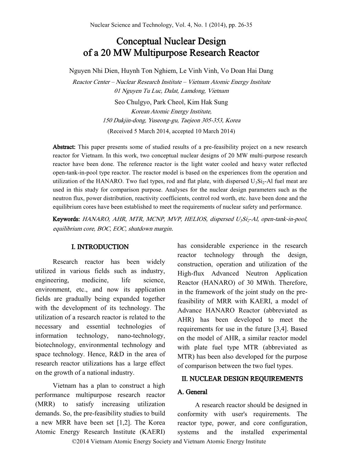
Conceptual nuclear design of a 20 MW multipurpose research reactor
This paper presents some of studied results of a pre-feasibility project on a new research
reactor for Vietnam. In this work, two conceptual nuclear designs of 20 MW multi-purpose research
reactor have been done. The reference reactor is the light water cooled and heavy water reflected
open-tank-in-pool type reactor. The reactor model is based on the experiences from the operation and
utilization of the HANARO. Two fuel types, rod and flat plate, with dispersed U3Si2-Al fuel meat are
used in this study for comparison purpose. Analyses for the nuclear design parameters such as the
neutron flux, power distribution, reactivity coefficients, control rod worth, etc. have been done and the
equilibrium cores have been established to meet the requirements of nuclear safety and performance.
Trang 1
Trang 2
Trang 3
Trang 4
Trang 5
Trang 6
Trang 7
Trang 8
Trang 9
Trang 10
Tóm tắt nội dung tài liệu: Conceptual nuclear design of a 20 MW multipurpose research reactor
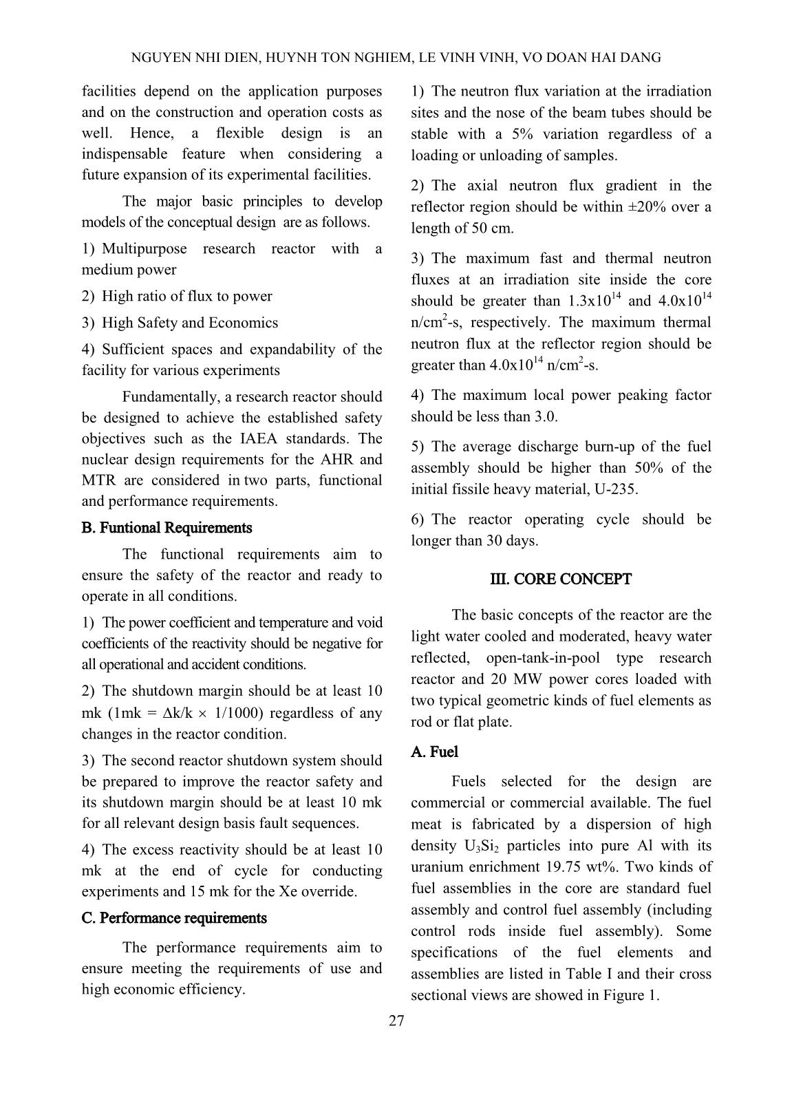
d MTR standard and control fuel assemblies
B. Core Arrangement
The core has 23 lattices that consist of
fourteen standard assemblies, four control
assemblies and three in-core irradiation sites.
The heavy water reflector tank of 200 cm in
diameter and 120 cm in height surrounds the
core. The reactor regulating system shares
control rods with the reactor protection system.
Fig. 2 shows the horizontal cross sectional
view of the AHR and MTR cores. Some
specifications of the cores are listed in Table II.
Fig. 2. The horizontal cross sectional view of the AHR and MTR cores
 a) AHR standard b) AHR Control c) MTR standard d) MTR control
NGUYEN NHI DIEN, HUYNH TON NGHIEM, LE VINH VINH, VO DOAN HAI DANG
29
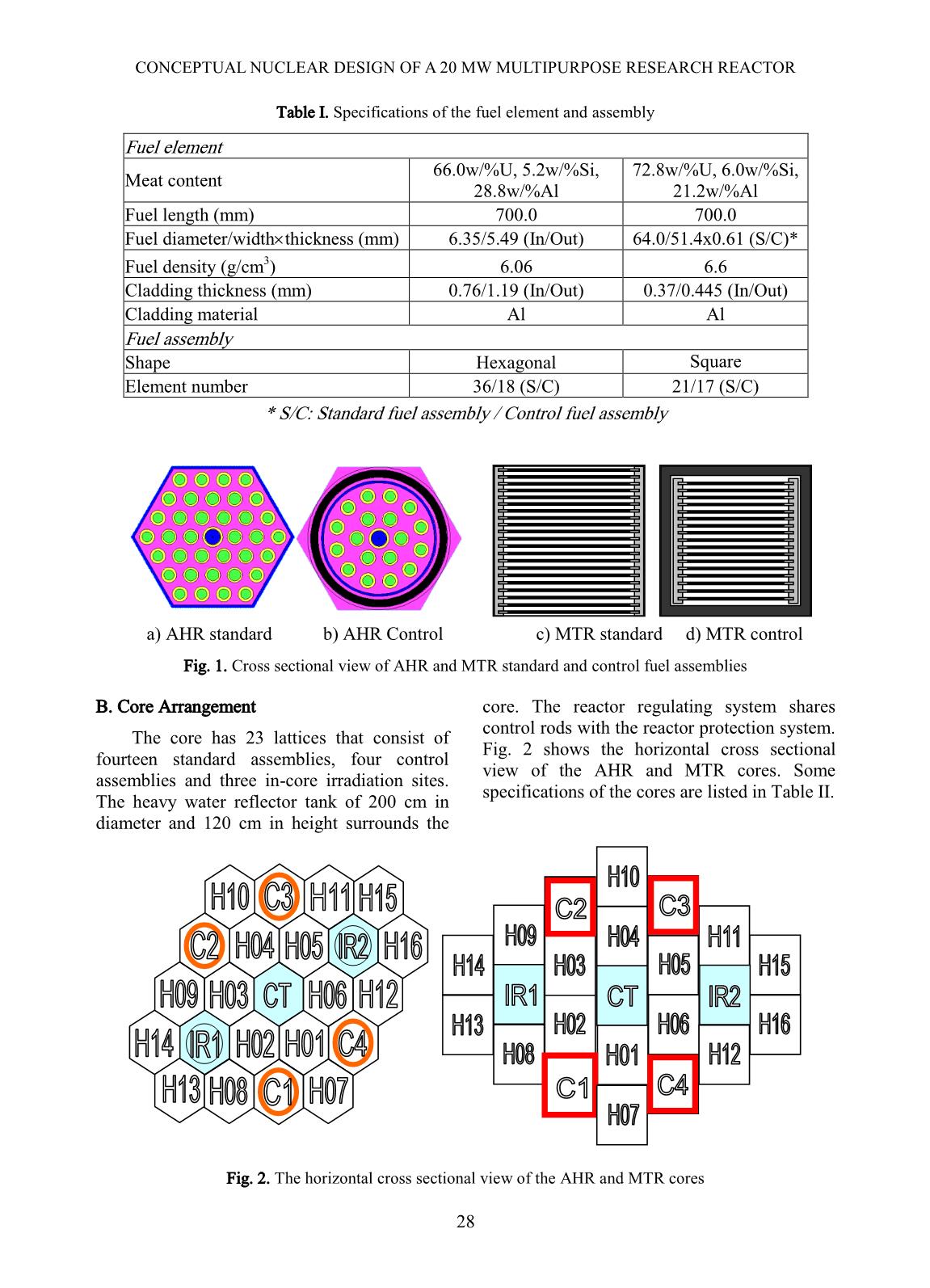
Table II. The specifications of the cores
Reactor type AHR MTR
Core volume (cm3) 1199.5 x 70 1527.7 x 70
Fuel assembly Number 16 S + 4 C 16 S + 4 C
Control rod Number 4 4
Absorber material Hf Hf
Total weight U-235 (kg) 9,87 10,12
In-core irradiation sites 3 3
IV. NUCLEAR ANALYSIS
To confirm that the conceptual cores
satisfy the functional and performance
requirements, nuclear analyses are performed
for fresh core and equilibrium core with
several code systems such as MCNP [5], MVP
[6], HELIOS [7], etc.
A. Fresh Core
The basic analysis of the core
characteristics was performed for the fresh core
with and without irradiation facilities.
The core configuration should be
designed to meet the functional and
performance requirements. The neutron flux at
the in-core irradiation sites and the reflector
region of the cores without irradiation facilities
was calculated by the MCNPX code [8] using a
mesh tally. On the other hand, the power
distribution, the reactivity of the core and the
reactivity worth of control rods were also
assessed to meet the requirements. Two core
configurations with one and three in-core
irradiation sites were proposed. Although the
first configuration (with one irradiation site) is
better in the fuel saving point of view, the
configuration with three in-core irradiation
sites was selected to meet predicted utilization
of in-core irradiation in the future.
As the ultimate goal of a research reactor
is its utilization, the irradiation facilities should
be designed in conformity with the user's
requirements. The required irradiation facilities
should be located at proper positions to
maximize neutron utilization and minimize
reactivity effect. Based on the neutron flux
distribution of the reflector region, the
arrangement by their purposes has been studied
to achieve the objectives above. Their
Fig. 3. The layout of the experimental sites of the AHR and MTR
CONCEPTUAL NUCLEAR DESIGN OF A 20 MW MULTIPURPOSE RESEARCH REACTOR
30
reactivity worth is considered as a priority
because of the influence to the reactor core.
Various layouts of the irradiation facilities
were proposed, and one of them was selected.
To evaluate the stability of neutron flux at the
irradiation sites, their neutron fluxes were
calculated when the control rods are located at
300 mm and fully withdrawn.
The reactivity effect by the irradiation
facilities was estimated to be 20.2 mk and 28.9
mk and the total control rods worth 182.4 mk
and 217.7 mk for AHR and MTR, respectively.
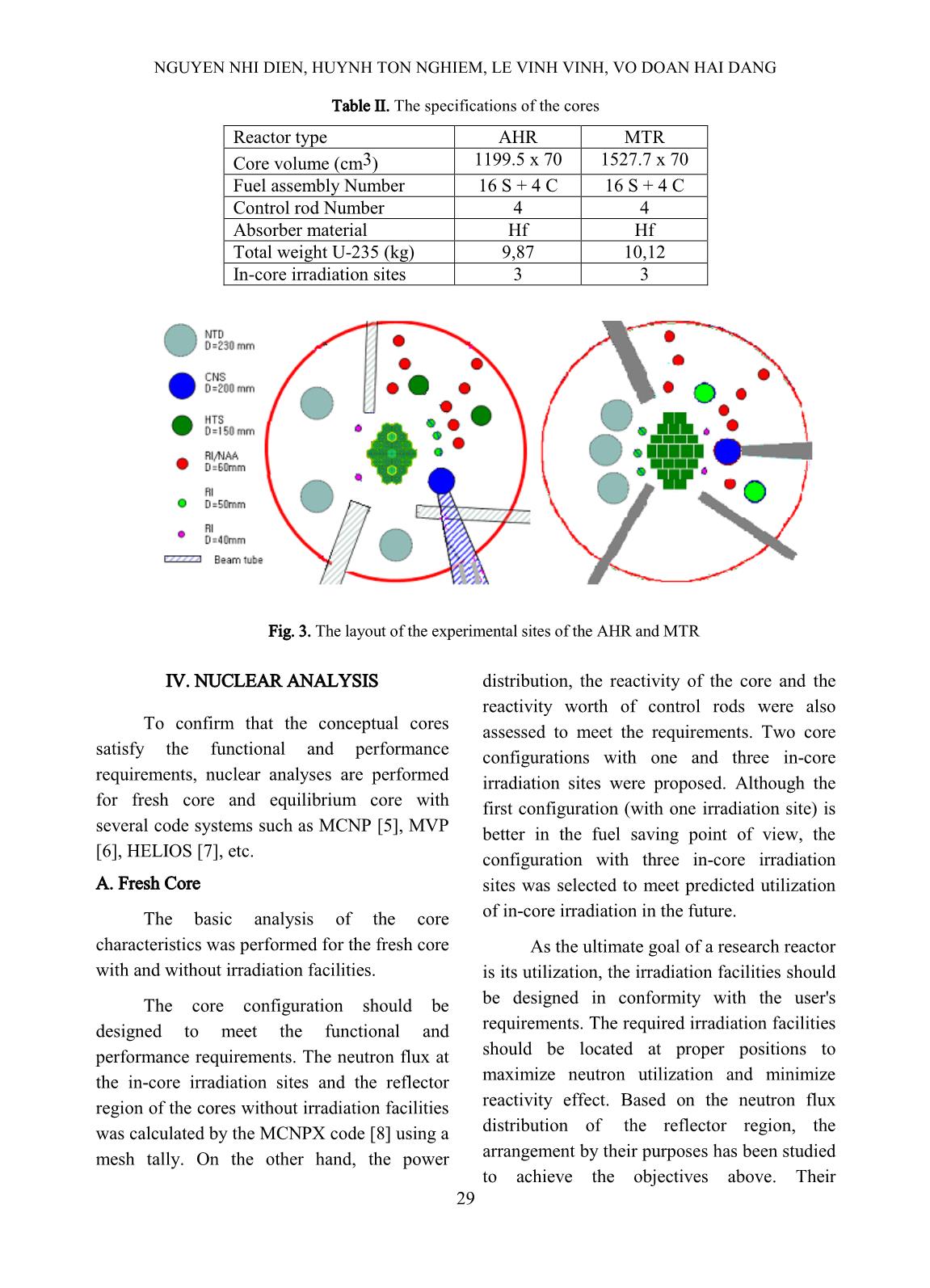
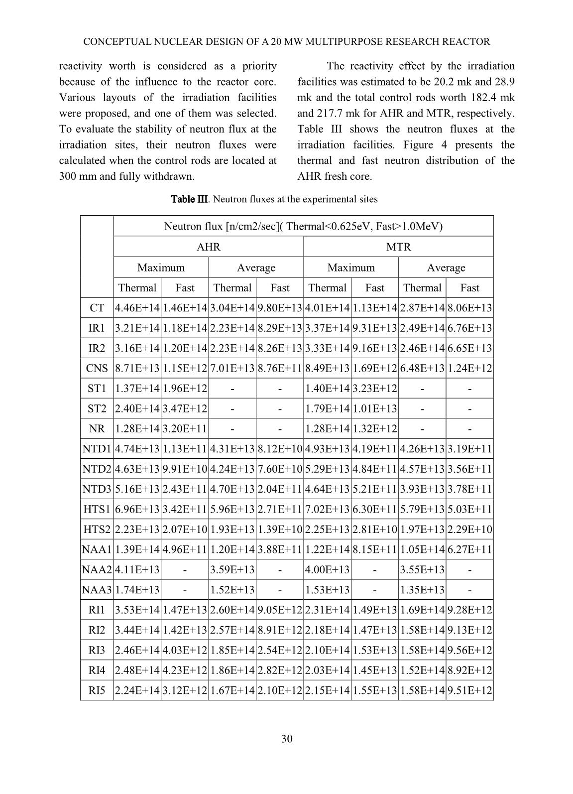
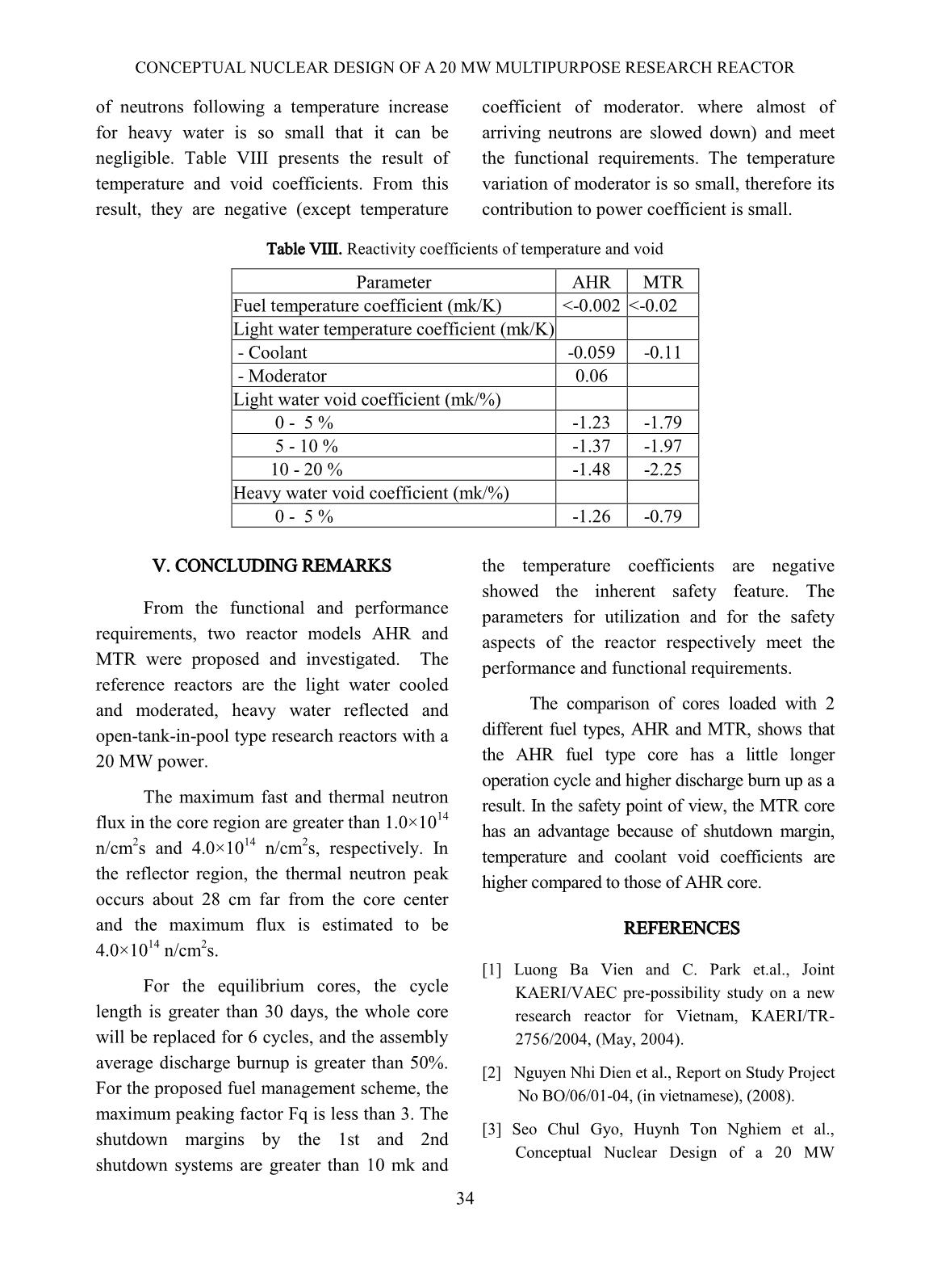
Table III shows the neutron fluxes at the
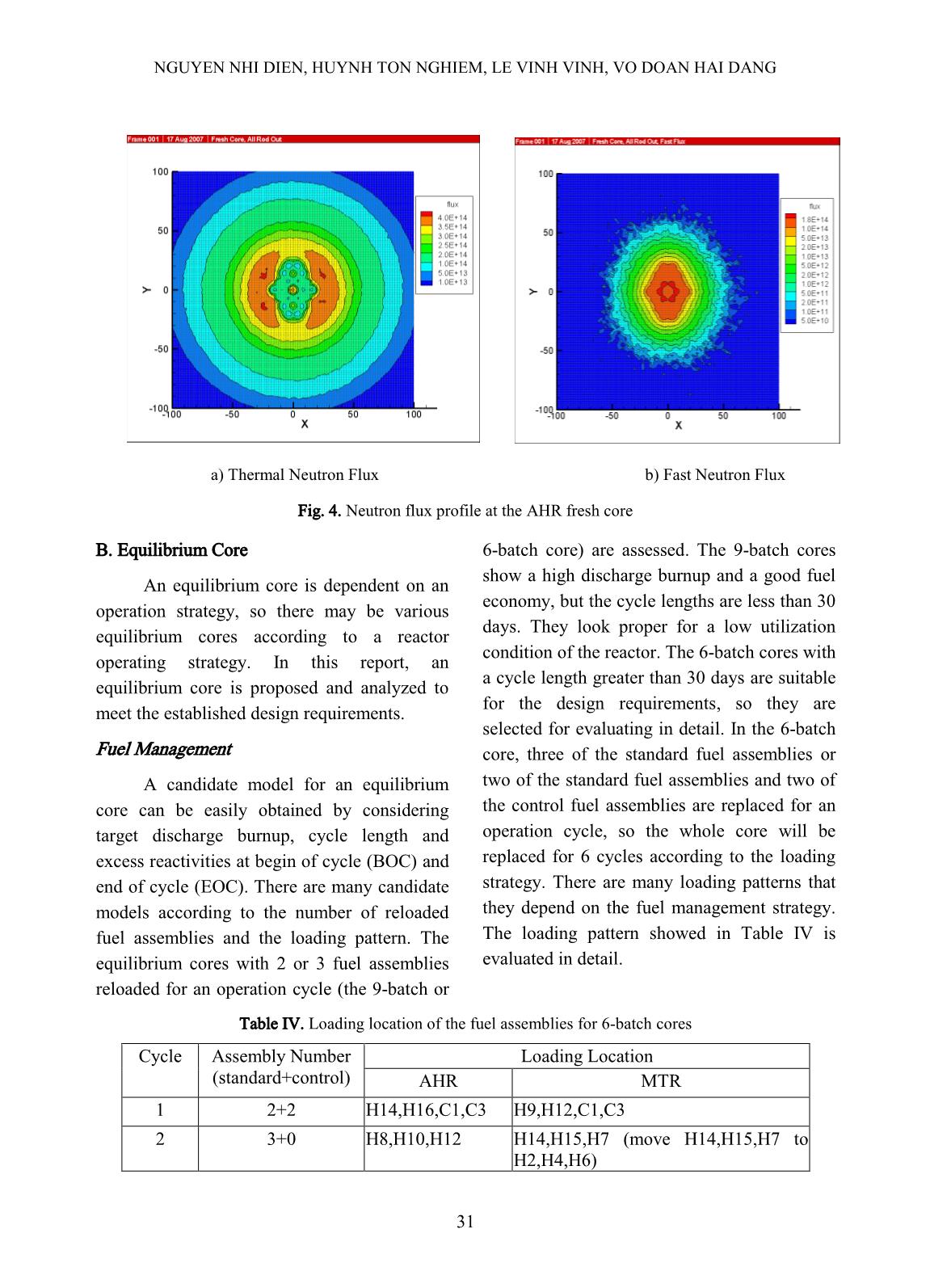
irradiation facilities. Figure 4 presents the
thermal and fast neutron distribution of the
AHR fresh core.
Table III. Neutron fluxes at the experimental sites
Neutron flux [n/cm2/sec]( Thermal1.0MeV)
AHR MTR
Maximum Average Maximum Average
Thermal Fast Thermal Fast Thermal Fast Thermal Fast
CT 4.46E+14 1.46E+14 3.04E+14 9.80E+13 4.01E+14 1.13E+14 2.87E+14 8.06E+13
IR1 3.21E+14 1.18E+14 2.23E+14 8.29E+13 3.37E+14 9.31E+13 2.49E+14 6.76E+13
IR2 3.16E+14 1.20E+14 2.23E+14 8.26E+13 3.33E+14 9.16E+13 2.46E+14 6.65E+13
CNS 8.71E+13 1.15E+12 7.01E+13 8.76E+11 8.49E+13 1.69E+12 6.48E+13 1.24E+12
ST1 1.37E+14 1.96E+12 - - 1.40E+14 3.23E+12 - -
ST2 2.40E+14 3.47E+12 - - 1.79E+14 1.01E+13 - -
NR 1.28E+14 3.20E+11 - - 1.28E+14 1.32E+12 - -
NTD1 4.74E+13 1.13E+11 4.31E+13 8.12E+10 4.93E+13 4.19E+11 4.26E+13 3.19E+11
NTD2 4.63E+13 9.91E+10 4.24E+13 7.60E+10 5.29E+13 4.84E+11 4.57E+13 3.56E+11
NTD3 5.16E+13 2.43E+11 4.70E+13 2.04E+11 4.64E+13 5.21E+11 3.93E+13 3.78E+11
HTS1 6.96E+13 3.42E+11 5.96E+13 2.71E+11 7.02E+13 6.30E+11 5.79E+13 5.03E+11
HTS2 2.23E+13 2.07E+10 1.93E+13 1.39E+10 2.25E+13 2.81E+10 1.97E+13 2.29E+10
NAA1 1.39E+14 4.96E+11 1.20E+14 3.88E+11 1.22E+14 8.15E+11 1.05E+14 6.27E+11
NAA2 4.11E+13 - 3.59E+13 - 4.00E+13 - 3.55E+13 -
NAA3 1.74E+13 - 1.52E+13 - 1.53E+13 - 1.35E+13 -
RI1 3.53E+14 1.47E+13 2.60E+14 9.05E+12 2.31E+14 1.49E+13 1.69E+14 9.28E+12
RI2 3.44E+14 1.42E+13 2.57E+14 8.91E+12 2.18E+14 1.47E+13 1.58E+14 9.13E+12
RI3 2.46E+14 4.03E+12 1.85E+14 2.54E+12 2.10E+14 1.53E+13 1.58E+14 9.56E+12
RI4 2.48E+14 4.23E+12 1.86E+14 2.82E+12 2.03E+14 1.45E+13 1.52E+14 8.92E+12
RI5 2.24E+14 3.12E+12 1.67E+14 2.10E+12 2.15E+14 1.55E+13 1.58E+14 9.51E+12
NGUYEN NHI DIEN, HUYNH TON NGHIEM, LE VINH VINH, VO DOAN HAI DANG
31
Fig. 4. Neutron flux profile at the AHR fresh core
B. Equilibrium Core
An equilibrium core is dependent on an
operation strategy, so there may be various
equilibrium cores according to a reactor
operating strategy. In this report, an
equilibrium core is proposed and analyzed to
meet the established design requirements.
Fuel Management
A candidate model for an equilibrium
core can be easily obtained by considering
target discharge burnup, cycle length and
excess reactivities at begin of cycle (BOC) and
end of cycle (EOC). There are many candidate
models according to the number of reloaded
fuel assemblies and the loading pattern. The
equilibrium cores with 2 or 3 fuel assemblies
reloaded for an operation cycle (the 9-batch or
6-batch core) are assessed. The 9-batch cores
show a high discharge burnup and a good fuel
economy, but the cycle lengths are less than 30
days. They look proper for a low utilization
condition of the reactor. The 6-batch cores with
a cycle length greater than 30 days are suitable
for the design requirements, so they are
selected for evaluating in detail. In the 6-batch
core, three of the standard fuel assemblies or
two of the standard fuel assemblies and two of
the control fuel assemblies are replaced for an
operation cycle, so the whole core will be
replaced for 6 cycles according to the loading
strategy. There are many loading patterns that
they depend on the fuel management strategy.
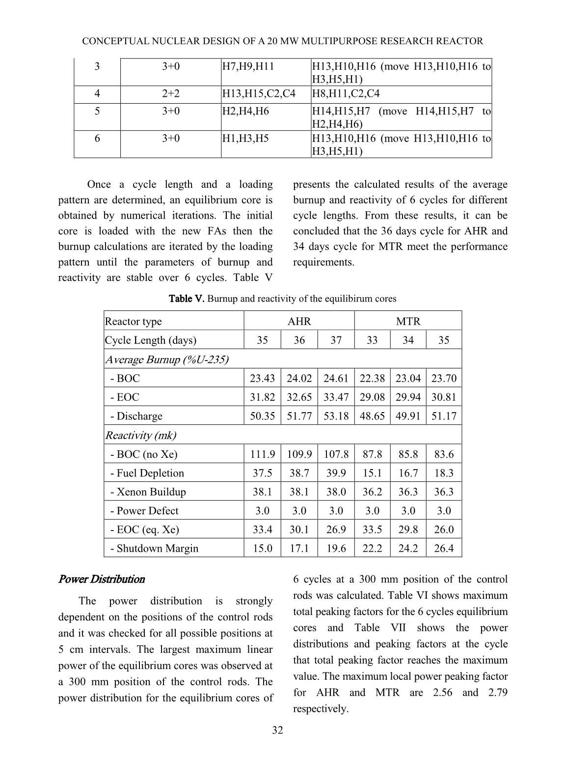
The loading pattern showed in Table IV is
evaluated in detail.
Table IV. Loading location of the fuel assemblies for 6-batch cores
Cycle Assembly Number
(standard+control)
Loading Location
AHR MTR
1 2+2 H14,H16,C1,C3 H9,H12,C1,C3
2 3+0 H8,H10,H12 H14,H15,H7 (move H14,H15,H7 to
H2,H4,H6)
 a) Thermal Neutron Flux b) Fast Neutron Flux
CONCEPTUAL NUCLEAR DESIGN OF A 20 MW MULTIPURPOSE RESEARCH REACTOR
30
3 3+0 H7,H9,H11 H13,H10,H16 (move H13,H10,H16 to
H3,H5,H1)
4 2+2 H13,H15,C2,C4 H8,H11,C2,C4
5 3+0 H2,H4,H6 H14,H15,H7 (move H14,H15,H7 to
H2,H4,H6)
6 3+0 H1,H3,H5 H13,H10,H16 (move H13,H10,H16 to
H3,H5,H1)
Once a cycle length and a loading
pattern are determined, an equilibrium core is
obtained by numerical iterations. The initial
core is loaded with the new FAs then the
burnup calculations are iterated by the loading
pattern until the parameters of burnup and
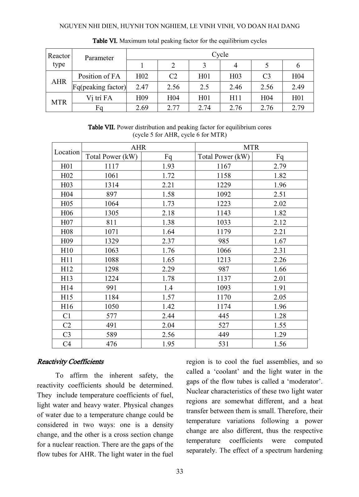
reactivity are stable over 6 cycles. Table V
presents the calculated results of the average
burnup and reactivity of 6 cycles for different
cycle lengths. From these results, it can be
concluded that the 36 days cycle for AHR and
34 days cycle for MTR meet the performance
requirements.
Table V. Burnup and reactivity of the equilibirum cores
Reactor type AHR MTR
Cycle Length (days) 35 36 37 33 34 35
Average Burnup (%U-235)
 - BOC 23.43 24.02 24.61 22.38 23.04 23.70
 - EOC 31.82 32.65 33.47 29.08 29.94 30.81
 - Discharge 50.35 51.77 53.18 48.65 49.91 51.17
Reactivity (mk)
 - BOC (no Xe) 111.9 109.9 107.8 87.8 85.8 83.6
 - Fuel Depletion 37.5 38.7 39.9 15.1 16.7 18.3
 - Xenon Buildup 38.1 38.1 38.0 36.2 36.3 36.3
 - Power Defect 3.0 3.0 3.0 3.0 3.0 3.0
 - EOC (eq. Xe) 33.4 30.1 26.9 33.5 29.8 26.0
 - Shutdown Margin 15.0 17.1 19.6 22.2 24.2 26.4
Power Distribution
The power distribution is strongly
dependent on the positions of the control rods
and it was checked for all possible positions at
5 cm intervals. The largest maximum linear
power of the equilibrium cores was observed at
a 300 mm position of the control rods. The
power distribution for the equilibrium cores of
6 cycles at a 300 mm position of the control
rods was calculated. Table VI shows maximum
total peaking factors for the 6 cycles equilibrium
cores and Table VII shows the power
distributions and peaking factors at the cycle
that total peaking factor reaches the maximum
value. The maximum local power peaking factor
for AHR and MTR are 2.56 and 2.79
respectively.
32
NGUYEN NHI DIEN, HUYNH TON NGHIEM, LE VINH VINH, VO DOAN HAI DANG
33
Table VI. Maximum total peaking factor for the equilibrium cycles
Reactor
type
Parameter
Cycle
1 2 3 4 5 6
AHR
Position of FA H02 C2 H01 H03 C3 H04
Fq(peaking factor) 2.47 2.56 2.5 2.46 2.56 2.49
MTR
Vị trí FA H09 H04 H01 H11 H04 H01
Fq 2.69 2.77 2.74 2.76 2.76 2.79
Table VII. Power distribution and peaking factor for equilibrium cores
(cycle 5 for AHR, cycle 6 for MTR)
Location
AHR MTR
Total Power (kW) Fq Total Power (kW) Fq
H01 1117 1.93 1167 2.79
H02 1061 1.72 1158 1.82
H03 1314 2.21 1229 1.96
H04 897 1.58 1092 2.51
H05 1064 1.73 1223 2.02
H06 1305 2.18 1143 1.82
H07 811 1.38 1033 2.12
H08 1071 1.64 1179 2.21
H09 1329 2.37 985 1.67
H10 1063 1.76 1066 2.31
H11 1088 1.65 1213 2.26
H12 1298 2.29 987 1.66
H13 1224 1.78 1137 2.01
H14 991 1.4 1093 1.91
H15 1184 1.57 1170 2.05
H16 1050 1.42 1174 1.96
C1 577 2.44 445 1.28
C2 491 2.04 527 1.55
C3 589 2.56 449 1.29
C4 476 1.95 531 1.56
Reactivity Coefficients
To affirm the inherent safety, the
reactivity coefficients should be determined.
They include temperature coefficients of fuel,
light water and heavy water. Physical changes
of water due to a temperature change could be
considered in two ways: one is a density
change, and the other is a cross section change
for a nuclear reaction. There are the gaps of the
flow tubes for AHR. The light water in the fuel
region is to cool the fuel assemblies, and so
called a ‘coolant’ and the light water in the
gaps of the flow tubes is called a ‘moderator’.
Nuclear characteristics of these two light water
regions are somewhat different, and a heat
transfer between them is small. Therefore, their
temperature variations following a power
change are also different, thus the respective
temperature coefficients were computed
separately. The effect of a spectrum hardening
CONCEPTUAL NUCLEAR DESIGN OF A 20 MW MULTIPURPOSE RESEARCH REACTOR
34
of neutrons following a temperature increase
for heavy water is so small that it can be
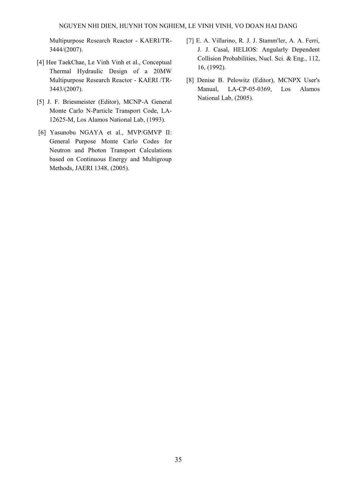
negligible. Table VIII presents the result of
temperature and void coefficients. From this
result, they are negative (except temperature
coefficient of moderator. where almost of
arriving neutrons are slowed down) and meet
the functional requirements. The temperature
variation of moderator is so small, therefore its
contribution to power coefficient is small.
Table VIII. Reactivity coefficients of temperature and void
Parameter AHR MTR
Fuel temperature coefficient (mk/K) <-0.002 <-0.02
Light water temperature coefficient (mk/K)
 - Coolant -0.059 -0.11
 - Moderator 0.06
Light water void coefficient (mk/%)
 0 - 5 % -1.23 -1.79
 5 - 10 % -1.37 -1.97
 10 - 20 % -1.48 -2.25
Heavy water void coefficient (mk/%)
 0 - 5 % -1.26 -0.79
V. CONCLUDING REMARKS
From the functional and performance
requirements, two reactor models AHR and
MTR were proposed and investigated. The
reference reactors are the light water cooled
and moderated, heavy water reflected and
open-tank-in-pool type research reactors with a
20 MW power.
The maximum fast and thermal neutron
flux in the core region are greater than 1.0×10
14
n/cm
2
s and 4.0×10
14
 n/cm
2
s, respectively. In
the reflector region, the thermal neutron peak
occurs about 28 cm far from the core center
and the maximum flux is estimated to be
4.0×10
14
 n/cm
2
s.
For the equilibrium cores, the cycle
length is greater than 30 days, the whole core
will be replaced for 6 cycles, and the assembly
average discharge burnup is greater than 50%.
For the proposed fuel management scheme, the
maximum peaking factor Fq is less than 3. The
shutdown margins by the 1st and 2nd
shutdown systems are greater than 10 mk and
the temperature coefficients are negative
showed the inherent safety feature. The
parameters for utilization and for the safety
aspects of the reactor respectively meet the
performance and functional requirements.
The comparison of cores loaded with 2
different fuel types, AHR and MTR, shows that
the AHR fuel type core has a little longer
operation cycle and higher discharge burn up as a
result. In the safety point of view, the MTR core
has an advantage because of shutdown margin,
temperature and coolant void coefficients are
higher compared to those of AHR core.
REFERENCES
[1] Luong Ba Vien and C. Park et.al., Joint
KAERI/VAEC pre-possibility study on a new
research reactor for Vietnam, KAERI/TR-
2756/2004, (May, 2004).
[2] Nguyen Nhi Dien et al., Report on Study Project
No BO/06/01-04, (in vietnamese), (2008).
[3] Seo Chul Gyo, Huynh Ton Nghiem et al.,
Conceptual Nuclear Design of a 20 MW
NGUYEN NHI DIEN, HUYNH TON NGHIEM, LE VINH VINH, VO DOAN HAI DANG
35
Multipurpose Research Reactor - KAERI/TR-
3444/(2007).
[4] Hee TaekChae, Le Vinh Vinh et al., Conceptual
Thermal Hydraulic Design of a 20MW
Multipurpose Research Reactor - KAERI /TR-
3443/(2007).
[5] J. F. Briesmeister (Editor), MCNP-A General
Monte Carlo N-Particle Transport Code, LA-
12625-M, Los Alamos National Lab, (1993).
 [6] Yasunobu NGAYA et al., MVP/GMVP II:
General Purpose Monte Carlo Codes for
Neutron and Photon Transport Calculations
based on Continuous Energy and Multigroup
Methods, JAERI 1348, (2005).
 [7] E. A. Villarino, R. J. J. Stamm'ler, A. A. Ferri,
J. J. Casal, HELIOS: Angularly Dependent
Collision Probabilities, Nucl. Sci. & Eng., 112,
16, (1992).
 [8] Denise B. Pelowitz (Editor), MCNPX User's
Manual, LA-CP-05-0369, Los Alamos
National Lab, (2005).
File đính kèm:
 conceptual_nuclear_design_of_a_20_mw_multipurpose_research_r.pdf

