Thiết kế bộ điều khiển thích nghi L1 cho hệ thống tuabin gió PMSG
This paper focuses on the design of an L1 adaptive controller for a variable speed wind turbines on
a permanent magnet synchronous generator (PMSG) to maximize the wind power exploited in the
presence of parameters uncertainties and wind speed turbulences. This control method based on the
class of state feedback state for multiinput multi-output (MIMO) system can be applied to the current
control and speed control of the system. The proposed controller successfully deals with the essential
nonlinear problems of wind turbines and the effect of unknown parameters. Moreover, the L1 adaptive
controller with fast adaptation is not only beneficial for both performance and robustness but also
effective for the appearance of the time-delay state variables of wind turbine. Finally, with comparison to
the indirect model reference adaptive control (MRAC), the performances of the system are verified by
mean of several simulation results.
Trang 1
Trang 2
Trang 3
Trang 4

Trang 5
Trang 6
Trang 7
Trang 8

Trang 9

Trang 10
Tóm tắt nội dung tài liệu: Thiết kế bộ điều khiển thích nghi L1 cho hệ thống tuabin gió PMSG
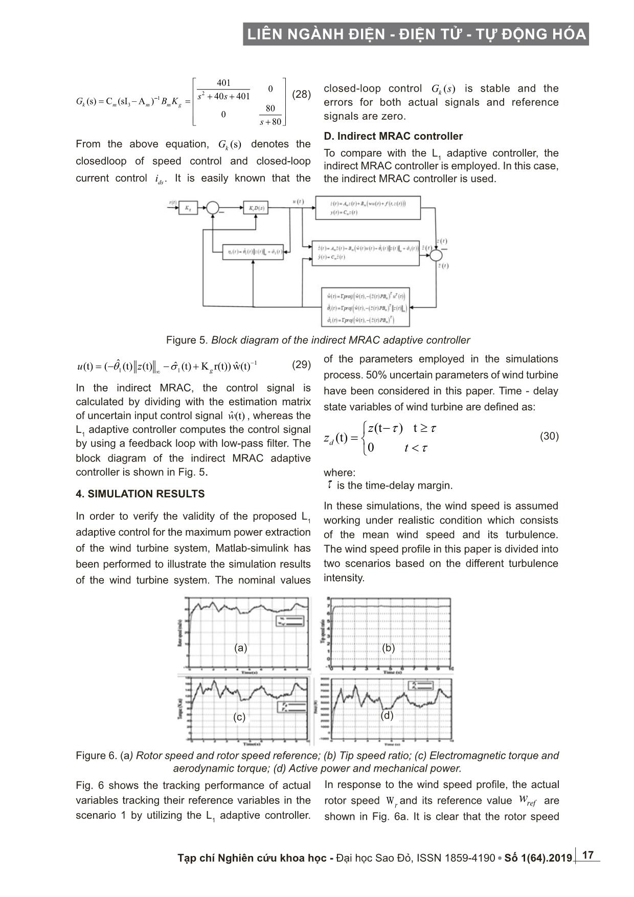
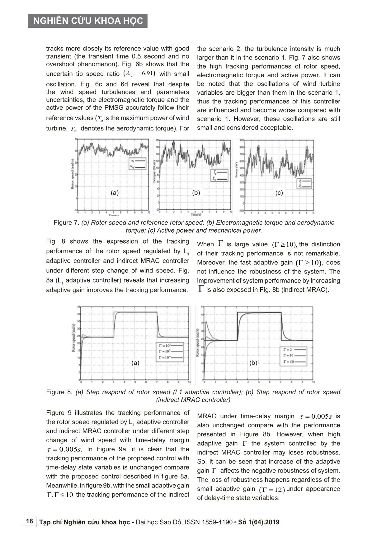
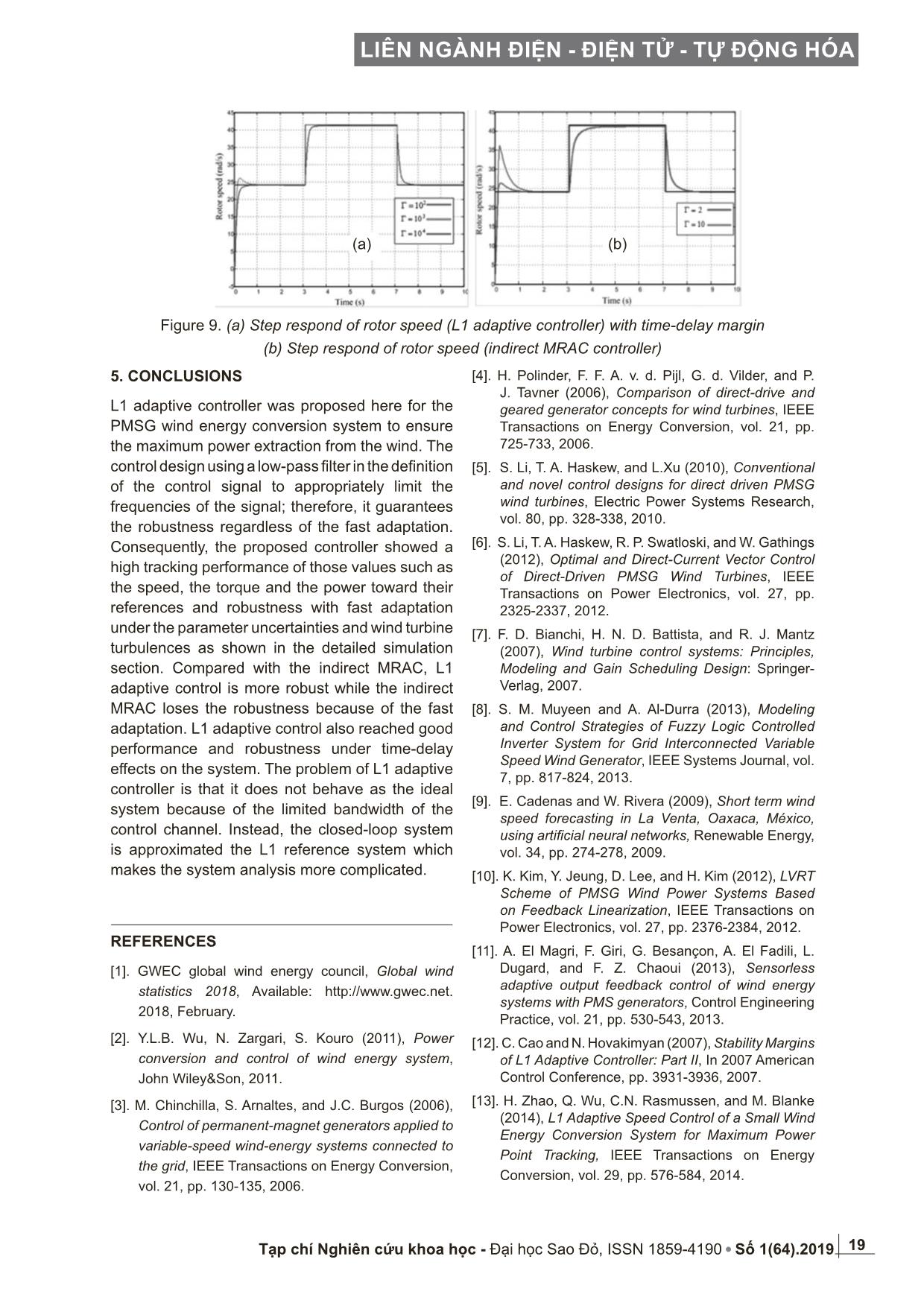
n feedback K. Therefore, it brings quick response and good performance of this system. However, it reduces the phase margin and the robustness of the system. In this paper, the second method is chosen by fixing H(s) and minimizing 1 2(s)(I C(s)) .LH − The H(s) is fixed by choosing its appropriate poles. From equation ((9)-(16)), the nominal matrix nA can be calculated as 0 067 9 31 0 1672 6 808 4 0 0 0 808 4 nA − ⋅ − ⋅ = − ⋅ − ⋅ ⋅ The feedback gain K is determined by Matlab [ ]1 2 3(A,B, , , )command K place p p p= 1715 4 768 5 0 0 0 80 K − ⋅ − ⋅ = − The Hurwitz matrix mA can be calculated as follows 0 067 9 31 0 42 7846 39 933 0 0 0 80 m nA A BK − ⋅ − ⋅ = − = ⋅ − ⋅ − mA is the Hurwitz matrix designed for the closed- loop control system ensure the stability of closed system due to the poles of closed-loop system 1 2,p p and 3 p also have the negative real part. Next, the system 1 1 2(s) (s)(I C(s))L LG H= − is minimized by choosing C(s). According to [14], the simplest choice 2 (s) c c wK C sI wK = + is obtained by letting 1 0 (s) 1 0 s D s = . The cascade system 1 (s) L G can be rendered arbitrarily small by increasing the bandwidth of low-pass filter C(s). If the bandwidth C(s) moves to infinite, 1 2(s)(I C(s)) 0LH − = would be obtained. The transfer function of the closed-loop system is approximating to following equation. 0 1 1 10 1 1 10 ˆ ˆ ˆ ˆ( ) ( ( ), ( ( ) ) ( )); (0) ˆ ˆ ˆˆ( ) ( ( ), ( ( ) ) ( ) ); (0) ˆ ˆ ˆ ˆ( ) ( ( ), ( ( ) ) ); (0) T T m T m T m w t proj w t z t PB u t w w t proj w t z t PB z t t proj w t z t PB θ θ θ σ σ σ ∞ = Γ − = = Γ − = = Γ − = ɺ ɶ ɺ ɶ ɺ ɶ ˆ( ) ( ) ( )cU s K D s sη= − 1 1 ˆˆ ˆ( ) ( ) ( ) ( ) ( ) ( ) ( )gt w t u t t z t t K r tη θ σ∞= + + − ( ) ( ) 1 1 ( ) r r g inLL L H s C s K r G s L B ρ ρ ρ ∞ − − = + (26) (27)1 1 43.72 0(C A B ) 0 80 g m m mK − − − = − = 17 LIÊN NGÀNH ĐIỆN - ĐIỆN TỬ - TỰ ĐỘNG HÓA Tạp chí Nghiên cứu khoa học - Đại học Sao Đỏ, ISSN 1859-4190 Số 1(64).2019 From the above equation, (s)kG denotes the closedloop of speed control and closed-loop current control .dsi It is easily known that the closed-loop control ( )kG s is stable and the errors for both actual signals and reference signals are zero. D. Indirect MRAC controller To compare with the L 1 adaptive controller, the indirect MRAC controller is employed. In this case, the indirect MRAC controller is used. Figure 5. Block diagram of the indirect MRAC adaptive controller In the indirect MRAC, the control signal is calculated by dividing with the estimation matrix of uncertain input control signal ˆ (t)w , whereas the L 1 adaptive controller computes the control signal by using a feedback loop with low-pass filter. The block diagram of the indirect MRAC adaptive controller is shown in Fig. 5. 4. SIMULATION RESULTS In order to verify the validity of the proposed L 1 adaptive control for the maximum power extraction of the wind turbine system, Matlab-simulink has been performed to illustrate the simulation results of the wind turbine system. The nominal values 1 1 1 ˆ ˆ ˆ(t) ( (t) (t) (t) K r(t)) w(t)gu zθ σ −∞= − − + (29) of the parameters employed in the simulations process. 50% uncertain parameters of wind turbine have been considered in this paper. Time - delay state variables of wind turbine are defined as: (t ) t (t) 0 d z z t τ τ τ − ≥ = < where: τ is the time-delay margin. In these simulations, the wind speed is assumed working under realistic condition which consists of the mean wind speed and its turbulence. The wind speed profile in this paper is divided into two scenarios based on the different turbulence intensity. (30) Figure 6. (a) Rotor speed and rotor speed reference; (b) Tip speed ratio; (c) Electromagnetic torque and aerodynamic torque; (d) Active power and mechanical power. (a) (c) (d) (b) 2 1 3 401 0 40 401 (s) C (sI A ) 80 0 80 k m m m g s s G B K s − + + = − = + (28) Fig. 6 shows the tracking performance of actual variables tracking their reference variables in the scenario 1 by utilizing the L 1 adaptive controller. In response to the wind speed profile, the actual rotor speed w r and its reference value refw are shown in Fig. 6a. It is clear that the rotor speed 18 NGHIÊN CỨU KHOA HỌC Tạp chí Nghiên cứu khoa học - Đại học Sao Đỏ, ISSN 1859-4190 Số 1(64).2019 the scenario 2, the turbulence intensity is much larger than it in the scenario 1. Fig. 7 also shows the high tracking performances of rotor speed, electromagnetic torque and active power. It can be noted that the oscillations of wind turbine variables are bigger than them in the scenario 1, thus the tracking performances of this controller are influenced and become worse compared with scenario 1. However, these oscillations are still small and considered acceptable. tracks more closely its reference value with good transient (the transient time 0.5 second and no overshoot phenomenon). Fig. 6b shows that the uncertain tip speed ratio ( )6.91optλ = with small oscillation. Fig. 6c and 6d reveal that despite the wind speed turbulences and parameters uncertainties, the electromagnetic torque and the active power of the PMSG accurately follow their reference values ( mT is the maximum power of wind turbine, mT denotes the aerodynamic torque). For Figure 7. (a) Rotor speed and reference rotor speed; (b) Electromagnetic torque and aerodynamic torque; (c) Active power and mechanical power. Fig. 8 shows the expression of the tracking performance of the rotor speed regulated by L 1 adaptive controller and indirect MRAC controller under different step change of wind speed. Fig. 8a (L 1 adaptive controller) reveals that increasing adaptive gain improves the tracking performance. Figure 8. (a) Step respond of rotor speed (L1 adaptive controller); (b) Step respond of rotor speed (indirect MRAC controller) Figure 9 illustrates the tracking performance of the rotor speed regulated by L 1 adaptive controller and indirect MRAC controller under different step change of wind speed with time-delay margin 0.005 .sτ = In Figure 9a, it is clear that the tracking performance of the proposed control with time-delay state variables is unchanged compare with the proposed control described in figure 8a. Meanwhile, in figure 9b, with the small adaptive gain , 10Γ Γ ≤ the tracking performance of the indirect MRAC under time-delay margin 0.005sτ = is also unchanged compare with the performance presented in Figure 8b. However, when high adaptive gain Γ the system controlled by the indirect MRAC controller may loses robustness. So, it can be seen that increase of the adaptive gain Γ affects the negative robustness of system. The loss of robustness happens regardless of the small adaptive gain ( )12Γ = under appearance of delay-time state variables. (a) (b) When Γ is large value ( 10),Γ ≥ the distinction of their tracking performance is not remarkable. Moreover, the fast adaptive gain ( 10),Γ ≥ does not influence the robustness of the system. The improvement of system performance by increasing Γ is also exposed in Fig. 8b (indirect MRAC). (a) (c)(b) 19 LIÊN NGÀNH ĐIỆN - ĐIỆN TỬ - TỰ ĐỘNG HÓA Tạp chí Nghiên cứu khoa học - Đại học Sao Đỏ, ISSN 1859-4190 Số 1(64).2019 5. CONCLUSIONS L1 adaptive controller was proposed here for the PMSG wind energy conversion system to ensure the maximum power extraction from the wind. The control design using a low-pass filter in the definition of the control signal to appropriately limit the frequencies of the signal; therefore, it guarantees the robustness regardless of the fast adaptation. Consequently, the proposed controller showed a high tracking performance of those values such as the speed, the torque and the power toward their references and robustness with fast adaptation under the parameter uncertainties and wind turbine turbulences as shown in the detailed simulation section. Compared with the indirect MRAC, L1 adaptive control is more robust while the indirect MRAC loses the robustness because of the fast adaptation. L1 adaptive control also reached good performance and robustness under time-delay effects on the system. The problem of L1 adaptive controller is that it does not behave as the ideal system because of the limited bandwidth of the control channel. Instead, the closed-loop system is approximated the L1 reference system which makes the system analysis more complicated. REFERENCES [1]. GWEC global wind energy council, Global wind statistics 2018, Available: 2018, February. [2]. Y.L.B. Wu, N. Zargari, S. Kouro (2011), Power conversion and control of wind energy system, John Wiley&Son, 2011. [3]. M. Chinchilla, S. Arnaltes, and J.C. Burgos (2006), Control of permanent-magnet generators applied to variable-speed wind-energy systems connected to the grid, IEEE Transactions on Energy Conversion, vol. 21, pp. 130-135, 2006. Figure 9. (a) Step respond of rotor speed (L1 adaptive controller) with time-delay margin (b) Step respond of rotor speed (indirect MRAC controller) [4]. H. Polinder, F. F. A. v. d. Pijl, G. d. Vilder, and P. J. Tavner (2006), Comparison of direct-drive and geared generator concepts for wind turbines, IEEE Transactions on Energy Conversion, vol. 21, pp. 725-733, 2006. [5]. S. Li, T. A. Haskew, and L.Xu (2010), Conventional and novel control designs for direct driven PMSG wind turbines, Electric Power Systems Research, vol. 80, pp. 328-338, 2010. [6]. S. Li, T. A. Haskew, R. P. Swatloski, and W. Gathings (2012), Optimal and Direct-Current Vector Control of Direct-Driven PMSG Wind Turbines, IEEE Transactions on Power Electronics, vol. 27, pp. 2325-2337, 2012. [7]. F. D. Bianchi, H. N. D. Battista, and R. J. Mantz (2007), Wind turbine control systems: Principles, Modeling and Gain Scheduling Design: Springer- Verlag, 2007. [8]. S. M. Muyeen and A. Al-Durra (2013), Modeling and Control Strategies of Fuzzy Logic Controlled Inverter System for Grid Interconnected Variable Speed Wind Generator, IEEE Systems Journal, vol. 7, pp. 817-824, 2013. [9]. E. Cadenas and W. Rivera (2009), Short term wind speed forecasting in La Venta, Oaxaca, México, using artificial neural networks, Renewable Energy, vol. 34, pp. 274-278, 2009. [10]. K. Kim, Y. Jeung, D. Lee, and H. Kim (2012), LVRT Scheme of PMSG Wind Power Systems Based on Feedback Linearization, IEEE Transactions on Power Electronics, vol. 27, pp. 2376-2384, 2012. [11]. A. El Magri, F. Giri, G. Besançon, A. El Fadili, L. Dugard, and F. Z. Chaoui (2013), Sensorless adaptive output feedback control of wind energy systems with PMS generators, Control Engineering Practice, vol. 21, pp. 530-543, 2013. [12]. C. Cao and N. Hovakimyan (2007), Stability Margins of L1 Adaptive Controller: Part II, In 2007 American Control Conference, pp. 3931-3936, 2007. [13]. H. Zhao, Q. Wu, C.N. Rasmussen, and M. Blanke (2014), L1 Adaptive Speed Control of a Small Wind Energy Conversion System for Maximum Power Point Tracking, IEEE Transactions on Energy Conversion, vol. 29, pp. 576-584, 2014. (a) (b) 20 NGHIÊN CỨU KHOA HỌC Tạp chí Nghiên cứu khoa học - Đại học Sao Đỏ, ISSN 1859-4190 Số 1(64).2019 THÔNG TIN TÁC GIẢ Trần Thị Điệp - Tóm tắt quá trình đào tạo, nghiên cứu (thời điểm tốt nghiệp và chương trình đào tạo, nghiên cứu): + Nĕm 2010: Tốt nghiệp Đại học Kỹ thuật công nghiệp Thái Nguyên chuyên ngành Điện tự động hóa + Nĕm 2013: Tốt nghiệp Thạc sĩ ngành Điện tự động hóa, Trường Đại học Mỏ địa chất Hà Nội + Từ nĕm 2010: Làm việc tại khoa Điện, Trường Đại học Sao Đỏ + Nĕm 2015:Làm nghiên cứu sinh tại Trường Đại học Hồ Nam, Trung Quốc - Hướng nghiên cứu hiện tại: Điều khiển các hệ thống phi tuyến, Rô bot, Nĕng lượng tái tạo bao gồm nĕng lượng gió và các hệ thống pin nhiên liệu, nĕng lượng mặt trời - Tóm tắt công việc hiện tại: Giảng viên tại khoa Điện, Trường Đại học Sao Đỏ - Điện thoại: 0374700015 - Email: phuongdiep222@gmail.com Vũ Đức Hà - Tóm tắt quá trình đào tạo, nghiên cứu (thời điểm tốt nghiệp và chương trình đào tạo, nghiên cứu): + Nĕm 2010: Tốt nghiệp Đại học Công nghiệp Hà Nội, chuyên ngành Kỹ thuật điện + Nĕm 2013: Tốt nghiệp Thạc sĩ ngành kỹ thuật điện Trường Đại học Mỏ địa chất Hà Nội + Từ nĕm 2010: Làm việc tại khoa Điện, Trường Đại học Sao Đỏ + Nĕm 2015: Làm nghiên cứu sinh tại Trường Đại học Hồ Nam, Trung Quốc - Hướng nghiên cứu hiện tại: Điều khiển các hệ thống phi tuyến, Rô bot, Nĕng lượng tái tạo bao gồm nĕng lượng gió và các hệ thống pin nhiên liệu, nĕng lượng mặt trời - Tóm tắt công việc hiện tại: Giảng viên tại khoa Điện, Trường Đại học Sao Đỏ - Điện thoại: 0983954486 - Email: vuhadhsd@gmail.com Phan Vĕn Phùng - Tóm tắt quá trình đào tạo, nghiên cứu (thời điểm tốt nghiệp và chương trình đào tạo, nghiên cứu): + Nĕm 1985: Tốt nghiệp Trường Cơ điện Chí Linh, Hải Dương chuyên ngành Điện +Từ nĕm 1985 đến nay làm việc tại Khoa Điện trường cơ điện Chí Linh nay là Trường Đại học Sao Đỏ + Nĕm 2003:Tốt nghiệp Trường Đại học Sư phạm I Hà Nội, ngành Kỹ thuật Điện + Nĕm 2009: Tốt nghiệp Thạc sĩ ngành tự động hoá đại học Trường Bách Khoa Hà Nội - Tóm tắt công việc hiện tại: Giảng viên tại khoa Điện Trường Đại học Sao Đỏ - Điện thoại: 0906283044 - Email: phungdhsd@gmail.com 21 LIÊN NGÀNH ĐIỆN - ĐIỆN TỬ - TỰ ĐỘNG HÓA Tạp chí Nghiên cứu khoa học - Đại học Sao Đỏ, ISSN 1859-4190 Số 1(64).2019 Huang Shou Dao - Tóm tắt quá trình đào tạo, nghiên cứu (thời điểm tốt nghiệp và chương trình đào tạo, nghiên cứu): + Nĕm 1983 và 2000: Cử nhân về Điện máy và Tiến sĩ về Kỹ thuật điện của Đại học Hồ Nam, Trung Quốc + Từ nĕm 1983 đến nĕm 1993: Làm việc tại Nhà máy Động cơ Hồ Nam với vai trò là Giám đốc kỹ thuật + Từ nĕm 1995: Đã làm việc với Trường Cao đẳng Kỹ thuật Điện và Thông tin, Đại học Hồ Nam + Từ nĕm 2008 đến 2009: Học giả thỉnh giảng tại Trường Đại học Nĕng lượng, Đại học Aalborg, Đan Mạch. Chủ tịch của Đại học Kỹ thuật Điện và Thông tin, Đại học Hồ Nam. Ông cũng là Giám đốc điều hành của Hiệp hội Điện tử Trung Quốc, Giám đốc Hiệp hội Tự động hóa Hồ Nam, Giám đốc Hiệp hội Nĕng lượng Trung Quốc và là thành viên của Ủy ban Hiệp hội Điện động cơ lớn của Trung Quốc + Lĩnh vực nghiên cứu hiện tại: Điện tử công suất và Công nghệ máy móc, Điều khiển bộ chuyển đổi nĕng lượng, Tự động hóa sản xuất điện gió và chất lượng điện nĕng - Tóm tắt công việc hiện tại: Phó Viện trưởng Viện Điện, Đại học Hồ Nam - Email: hsd1962@hnu.edu.cn - Điện thoại:13975113979
File đính kèm:
 thiet_ke_bo_dieu_khien_thich_nghi_l1_cho_he_thong_tuabin_gio.pdf

