Thermal distribution and reliability prediction for 3D networks-on-chip
As one of the most promising technologies to reduce footprint, power consumption and
wire latency, Three Dimensional Integrated Circuits (3D-ICs) is considered as the near future for
VLSI system. Combining with the Network-on-Chip infrastructure to obtain 3D Networks-onChip (3D-NoCs), the new on-chip communication paradigm brings several advantages. However,
thermal dissipation is one of the most critical challenges for 3D-ICs, where the heat cannot easily
transfer through several layers of silicon. Consequently, the high-temperature area also confronts
the reliability threat as the Mean Time to Failure (MTTF) decreases exponentially with the
operating temperature as in Black’s model. Apparently, 3D-NoCs and 3D ICs must tackle this
fundamental problem in order to be widely used. However, the thermal analyses usually require
complicated simulation and might cost an enormous execution time. As a closed-loop design flow,
designers may take several times to optimize their designs which significantly increase the thermal
analyzing time. Furthermore, reliability prediction also requires both completed design and
thermal prediction, and designer can use the result as a feedback for their optimization. As we can
observe two big gaps in the design flow, it is difficult to obtain both of them which put 3D-NoCs
under thermal throttling and reliability threats. Therefore, in this work, we investigate the thermal
distribution and reliability prediction of 3D-NoCs. We first propose a new method to help simulate
the temperature (both steady and transient) using traffic values from realistic and synthetic
benchmarks and the power consumption from standard VLSI design flow. Then, based on the
proposed method, we further predict the relative reliability between different parts of the network.
Experimental results show that the method has an extremely fast execution time in comparison to
the acceleration lifetime test. Furthermore, we compare the thermal behavior and reliability
between Monolithic design and TSV (Through-Silicon-Via) based design. We also explore the
ability to implement the thermal via a mechanism to help reduce the operating temperature.
Trang 1
Trang 2
Trang 3
Trang 4
Trang 5
Trang 6
Trang 7
Trang 8
Trang 9
Trang 10
Tải về để xem bản đầy đủ
Tóm tắt nội dung tài liệu: Thermal distribution and reliability prediction for 3D networks-on-chip
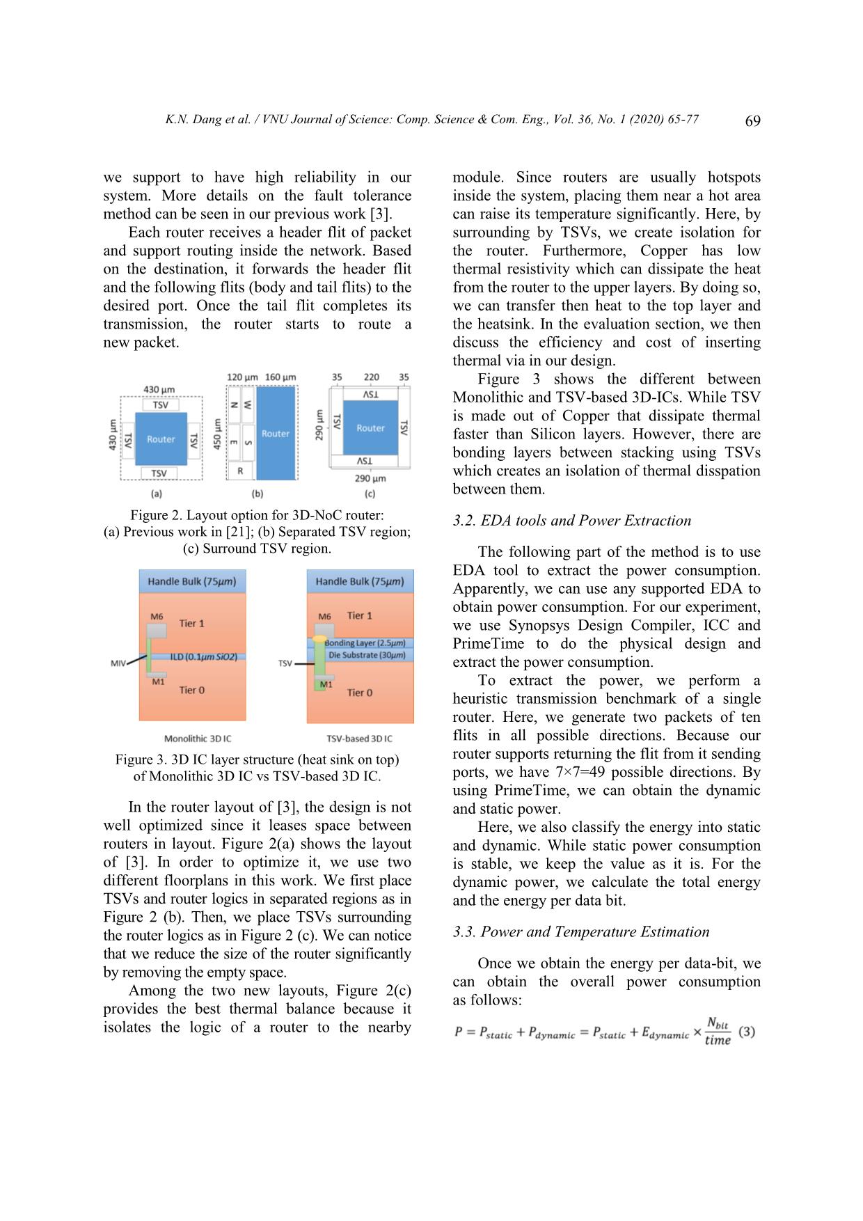
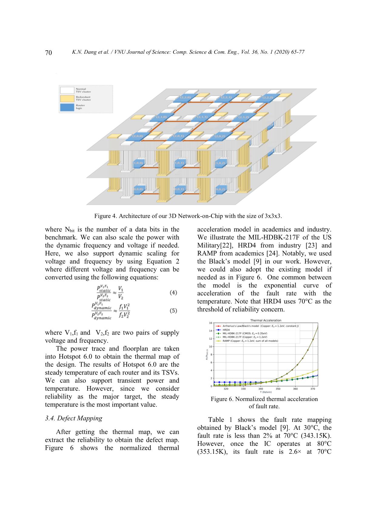
nchmark. With synthetic
also adopt the method in [32] where we remove benchmarks, TSV-based 3D-NoC is slightly
the bonding layers between silicon layers. We better than Monolithic ones.
keep the thickness of the silicon layer as it is for
a fair comparison. Obviously, if we thin the 4.4. Exploring Different Layout and Thermal
layer, the transfer of heat is much faster. Dissipation Method
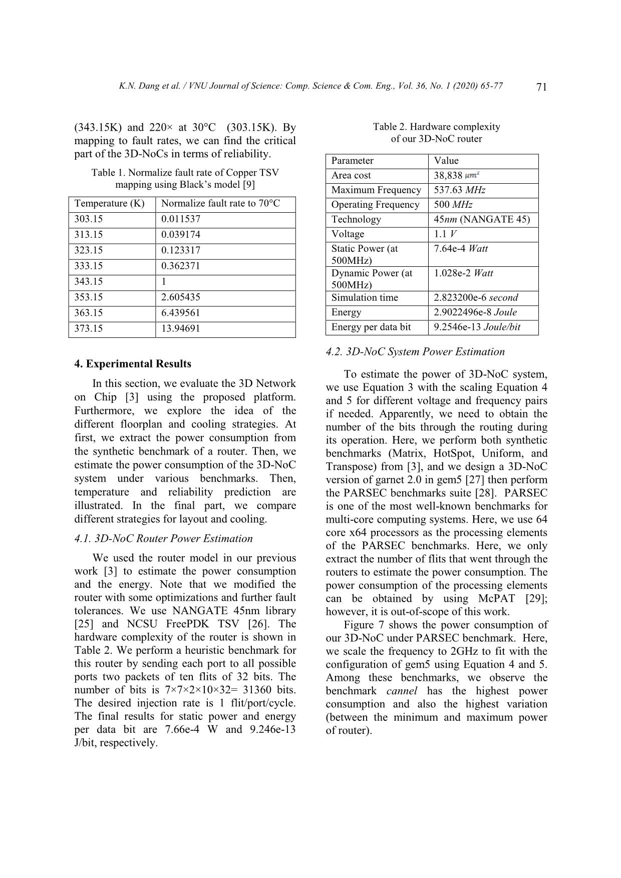
 Figure 9 shows the router temperature In this section, we explore different layouts
under the PARSEC benchmark. Here, we also and their thermal dissipation behaviors for our
compare with the monolithic technology where 3D-NoC. First, we perform thermal and
no TSV needed [32]. As we can observe in reliability prediction for our layout in Figure
Figure 9, the TSV-based system has lower 2(b). Then, we insert four thermal TSVs with
operating temperature thanks to the ability to the size 15 15 in four corners of the
transfer the heat of Copper TSVs. The
 router floorplan in Figure 2(c). This size of
difference in temperature is around 1K at TSV is still feasible in the existing manufacture
the bottom layer and even reach 3.5K in the
 process [7]. We also add 10 Keep-out-Zone
cannel benchmark.
 distance this thermal TSV to avoid mechanical
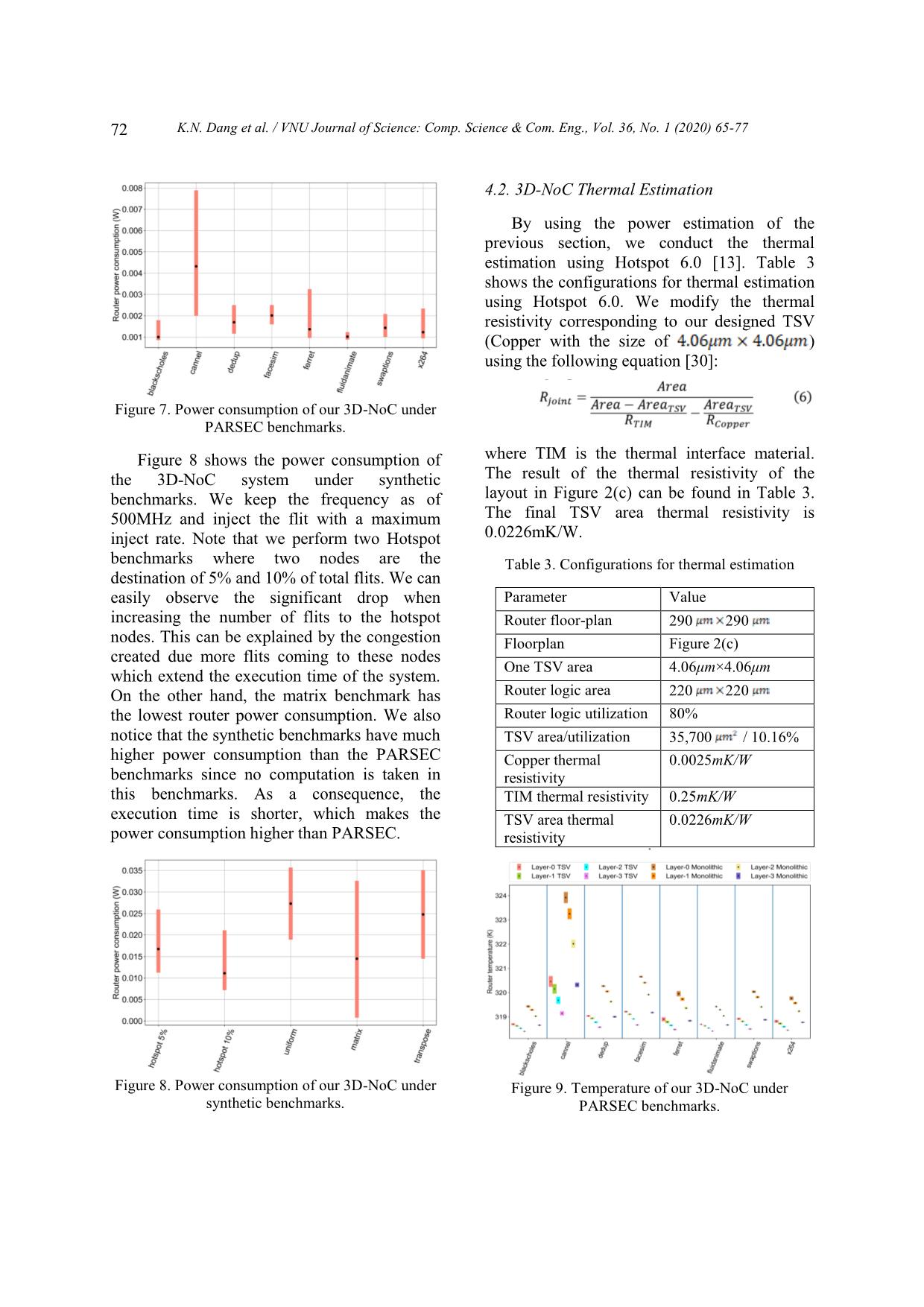
 Figure 10 shows the operating temperature
 stress. The thermal TSV went through all layers
under synthetic benchmarks of our 3D-NoC.
 of TSVs but did not contact with the heatsink.
We can easily notice that the operating
 The heatsink and thermal TSV are separated by
temperature of Monolithic systems is much
 a layer of thermal interface material.
higher than TSV ones since we stress the
system under its saturation points. The highest
temperature of Monolithic 3D-NoC even
reaches 351.64 K (78.49°C). The hottest layer
of the TSV-based system has a similar
temperature as the coolest layer of Monolithic
3D-NoC.
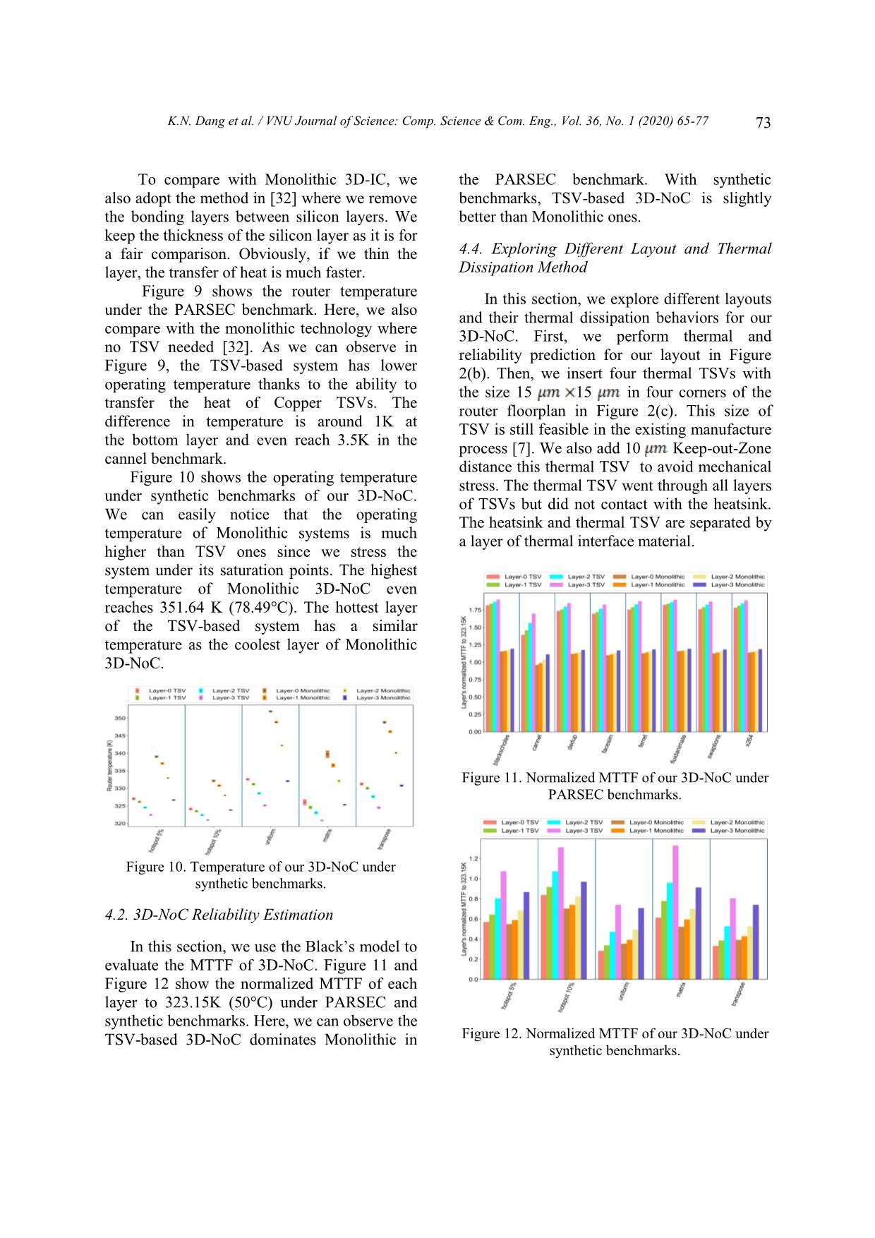
 Figure 11. Normalized MTTF of our 3D-NoC under
 PARSEC benchmarks.
 Figure 10. Temperature of our 3D-NoC under
 synthetic benchmarks.
4.2. 3D-NoC Reliability Estimation
 In this section, we use the Black’s model to
evaluate the MTTF of 3D-NoC. Figure 11 and
Figure 12 show the normalized MTTF of each
layer to 323.15K (50°C) under PARSEC and
synthetic benchmarks. Here, we can observe the
TSV-based 3D-NoC dominates Monolithic in Figure 12. Normalized MTTF of our 3D-NoC under
 synthetic benchmarks.
74 K.N. Dang et al. / VNU Journal of Science: Comp. Science & Com. Eng., Vol. 36, No. 1 (2020) 65-77
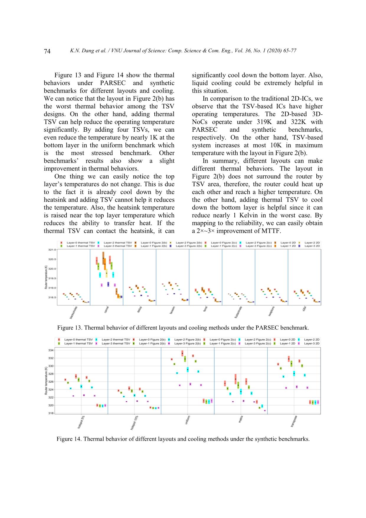
 Figure 13 and Figure 14 show the thermal significantly cool down the bottom layer. Also,
behaviors under PARSEC and synthetic liquid cooling could be extremely helpful in
benchmarks for different layouts and cooling. this situation.
We can notice that the layout in Figure 2(b) has In comparison to the traditional 2D-ICs, we
the worst thermal behavior among the TSV observe that the TSV-based ICs have higher
designs. On the other hand, adding thermal operating temperatures. The 2D-based 3D-
TSV can help reduce the operating temperature NoCs operate under 319K and 322K with
significantly. By adding four TSVs, we can PARSEC and synthetic benchmarks,
even reduce the temperature by nearly 1K at the respectively. On the other hand, TSV-based
bottom layer in the uniform benchmark which system increases at most 10K in maximum
is the most stressed benchmark. Other temperature with the layout in Figure 2(b).
benchmarks’ results also show a slight In summary, different layouts can make
improvement in thermal behaviors. different thermal behaviors. The layout in
 One thing we can easily notice the top Figure 2(b) does not surround the router by
layer’s temperatures do not change. This is due TSV area, therefore, the router could heat up
to the fact it is already cool down by the each other and reach a higher temperature. On
heatsink and adding TSV cannot help it reduces the other hand, adding thermal TSV to cool
the temperature. Also, the heatsink temperature down the bottom layer is helpful since it can
is raised near the top layer temperature which reduce nearly 1 Kelvin in the worst case. By
reduces the ability to transfer heat. If the mapping to the reliability, we can easily obtain
thermal TSV can contact the heatsink, it can a 2×~3× improvement of MTTF.
 G
 Figure 13. Thermal behavior of different layouts and cooling methods under the PARSEC benchmark.
 Figure 14. Thermal behavior of different layouts and cooling methods under the synthetic benchmarks.
 K.N. Dang et al. / VNU Journal of Science: Comp. Science & Com. Eng., Vol. 36, No. 1 (2020) 65-77 75
4.5. Execution Time TSV-based 3D-NoCs due to two major reasons:
 i) TSVs act like thermal conduct devices and
 In this work, we evaluate the proposed ii) Monolithic 3D-ICs has a higher density than
method using a system with Xeon E5-2620 8 TSV-based system. However, we would like to
cores 2.1GHz, 16GB RAM and Linux note that Monolithic 3D-ICs have lower area
Subsystem and PowerShell under Windows 10. cost than TSV-based systems.
The platform is written under C++, Python, and Fluid cooling [7] is one of the most
Bash. The execution time is measured using advanced methods to reduce the operating
command time under Linux and Measure- temperature of the system. Although we have
Command under Windows PowerShell. Here, not explored the ability of this method, it has
the simulation time of PARSEC and synthetic shown promising efficiency for 3D-ICs [7].
benchmarks are not considered because they are With a fast velocity of the fluid, we expect the
separated from our flow. As shown in Table 4, system can be cooled down significantly.
all steps in our flow perform under two seconds. However, we would like to note that fluid
Our method easily outperforms in terms of cooling has unknown reliability which needs to
execution time the fabrication-based methods be carefully investigated for being widely used.
which usually take hours regardless of designing,
fabrication and assembly time [10-12].
 5. Conclusion
 Table 4. Execution time of the proposed flow
 In this work, we proposed a platform to
 Work Step Time quickly estimate the power, thermal behavior,
 Ours Power extraction (one 1.22 s and reliability of 3D-NoC systems. The method
 benchmark) has shown extremely short execution time. We
 Floorplan generate 0.095 s also analyze and simulate the reliability of TSV
 Temperature estimation 81 s and Monolithic 3D-ICs. Furthermore, we
 (one benchmark) explore and compare different layout strategies
 Reliability estimation (12 1.12 s and cooling methods.
 benchmarks) From our experiments with 3D-NoC, we
 [10] Reliability test 96h can realize that lower index layers have higher
 [11] The longest step in 1000h operating temperatures and are more critical in
 reliability test terms of reliability. Although this conclusion
 [12] Lifetime acceleration test 100-5000h cannot cover all possible cases; this is a
 consensus of the tested benchmark Based on
 Although our approach is fater than these experiments, designers can decide their
real-chip testing [10-12], it cannot as accurate fault-tolerance or thermal dissipation up on
as the baking tests due to the deviations during their required specification.
simulation and the potential of manufacturing In the future, advanced cooling techniques
variation. However, as the close-loop design such as liquid could be investigated. The impact
flow, having an understand of the potential of DVFS and fault tolerance on performance
reliability threat is helpful for designers. and thermal behavior also could be studied.
4.6. Discussion
 In this section, we would like to discuss Acknowledgments
some technical details of our methods.
Advantages and drawbacks are also mentioned This research is funded by the Vietnam
in this part. National Foundation for Science and
 In our evaluation, we point out that Technology Development (NAFOSTED) under
Monolithic has a higher temperature than grant number 102.01-2018.312.
76 K.N. Dang et al. / VNU Journal of Science: Comp. Science & Com. Eng., Vol. 36, No. 1 (2020) 65-77
References [10] Hamada, M. Dorothy June, J. William, Roesch,
 "Evaluating device reliability using wafer-level
 methodology", CS Mantech Conference, 2008.
 [1] Khanh N. Dang, Akram Ben Ahmed, Xuan Tu [11] Renesas’s Semiconductor Reliability Handbook
 Tran, Yuichi Okuyama, Abderazek Ben Abdallah, https://www.renesas.com/us/en/doc/products/others/r
 “A Comprehensive Reliability Assessment of 51zz0001ej0250.pdf/, 2017 (access 17 March 2020).
 Fault-Resilient Network-on-Chip Using
 [12] Toshiba’s Reliability Handbook
 Analytical Model,” IEEE Transactions on Very
 https://toshiba.semicon-
 Large Scale Integration (VLSI) Systems. 25(11)
 storage.com/content/dam/toshiba-
 (2017) 3099-3112.
 ss/shared/docs/design-support/reliability/reliability-
 https://doi.org/10.1109/TVLSI.2017.2736004. handbook-tdsc-en.pdf /, 2018 (access 17 March 2020).
 [2] K. Banerjee K. Banerjee, S.J. Souri, P. Kapur and [13] Zhang, Runjie, Mircea R. Stan, Kevin
 K.C. Saraswat, “3-D ICs: A novel chip design for Skadron, “Hotspot 6.0: Validation,
 improving deep-submicrometer interconnect acceleration and extension”, University of
 performance and systems-on-chip integration,” Virginia, Tech, Rep, 2015.
 Proc. IEEE. 89(5) (201) 602-633.
 [14] Sridhar, Arvind, et al., "3D-ICE: Fast compact
 https://doi.org/10.1109/5.929647.
 transient thermal modeling for 3D ICs with inter-
 [3] Khanh N. Dang, Akram Ben Ahmed, Yuichi tier liquid cooling", 2010 IEEE/ACM
 Okuyama, Abderazek Ben Abdallah, “Scalable International Conference on Computer-Aided
 design methodology and online algorithm for Design (ICCAD), IEEE, 2010.
 TSV-cluster defects recovery in highly reliable
 [15] Scott Ladenheim, Yi-Chung Chen, Milan
 3D-NoC systems”, IEEE Transactions on
 Mihajlović, Vasilis F. Pavlidis, "The MTA: An
 Emerging Topics in Computing, 2017, pp. 1-14
 Advanced and Versatile Thermal Simulator for
 (in-press).
 Integrated Systems", IEEE Transactions on
 https://doi.org/10.1109/TETC.2017.2762407.
 Computer-Aided Design of Integrated Circuits
 [4] Wong, Simon, et al. "Monolithic 3D integrated and Systems 37(12) (2018) 3123-3136.
 circuits" International Symposium on VLSI https://doi.org/10.1109/TCAD.2018.2789729.
 Technology, Systems and Applications (VLSI-
 [16] Erdmann, Christophe, et al., "A heterogeneous
 TSA), IEEE, 2007.
 3D-IC consisting of two 28 nm FPGA die and 32
 [5] Y.J. Park et al., “Thermal Analysis for 3D Multi- reconfigurable high-performance data converters",
 core Processors with Dynamic Frequency IEEE Journal of Solid-State Circuits 50(1) (2014)
 Scaling”, in IEEE/ACIS 9th Int, Conf, on 258-269.
 Computer and Information Science, Aug 2010, https://doi.org/10.1109/JSSC.2014.2357432.
 pp. 69-74.
 [17] Kahng, B. Andrew, et al., "ORION 2.0: A fast and
 [6] Van der Plas, Geert, et al., "Design issues and accurate NoC power and area model for early-
 considerations for low-cost 3-D TSV IC stage design space exploration", Design,
 technology". IEEE Journal of Solid-State Circuits Automation & Test in Europe Conference &
 46(1) (2010) 293-307. Exhibition, IEEE, 2009.
 [7] D. Cuesta et al., “Thermal-aware floorplanner for [18] Lee, Seung Eun, and Nader Bagherzadeh, "A high
 3D IC, including TSVs, liquid microchannels and level power model for Network-on-Chip (NoC)
 thermal domains optimization,” Applied Soft router", Computers & Electrical Engineering
 Computing 34 (2015) 164-177. 35(6) (2009) 837-845.
 https://doi.org/10.1016/j.asoc.2015.04.052.
 https://doi.org/10.1016/j.compeleceng.2008.11.023.
 [8] Park, Changyok, "Dummy TSV to improve
 [19] Lee, Seung Eun, Nader Bagherzadeh, "A variable
 process uniformity and heat dissipation", U.S.
 frequency link for a power-aware network-on-
 Patent 10, 181, 454, 15 Jan, 2019.
 chip (NoC)", Integration 42(4) (2009) 479-485.
 https://patents.google.com/patent/US2011021545
 https://doi.org/10.1016/j.vlsi.2009.01.002.
 7A1/en (access 16 March 2020).
 [20] Lebreton, Hugo, Pascal Vivet, "Power modeling in
 [9] J.R. Black, “Mass transport of aluminum by
 SystemC at transaction level, application to a DVFS
 momentum exchange with conducting
 architecture", 2008 IEEE Computer Society Annual
 electrons”, in 6th Annual Reliability Physics
 Symposium on VLSI, IEEE, 2008.
 Symposium (IEEE), IEEE, 1967, pp. 148-159.
 [21] Khanh N. Dang Akram Ben Ahmed, Abderazek
 Ben Abdallah, Xuan-Tu Tran, “TSV-OCT: A
 K.N. Dang et al. / VNU Journal of Science: Comp. Science & Com. Eng., Vol. 36, No. 1 (2020) 65-77 77
 Scalable Online Multiple-TSV Defects [28] Bienia, Christian, et al., "The PARSEC
 Localization for Real-Time 3-D-IC systems” benchmark suite: Characterization and
 IEEE Transactions on Very Large Scale architectural implications", Proceedings of the
 Integration Systems 28(3) (2020) 672 - 685. 17th international conference on Parallel
 https://doi.org/10.1109/TVLSI.2019.2948878. architectures and compilation techniques, 2008.
[22] United States of America: Department of Defense, [29] Li, Sheng, et al., "McPAT: an integrated power, area
 Military Handbook: Reliability Prediction of and timing modeling framework for multicore and
 Electronic Equipment: MIL-HDBK-217F, 1991. manycore architectures", Proceedings of the 42nd
[23] J.B. Bowles, “A survey of reliability-prediction Annual IEEE/ACM International Symposium on
 procedures for microelectronic devices”, IEEE Microarchitecture, 2009.
 Trans, Rel. 41(1) (1992) 2-12. [30] J. Meng, K. Kawakami, A.K. Coskun,
 https://doi.org/10.1109/24.126662. “Optimizing energy efficiency of 3-d multicore
[24] J. Srinivasan et al., “Lifetime reliability: Toward an systems with stacked dram under power and
 architectural solution”, IEEE Micro. 25(3) (2005) thermal constraints”, in DAC Design Automation
 70-80. https://doi.org/10.1109/MM.2005.54. Conference 2012, IEEE, 2012, pp. 648-655.
[25] NanGate Inc., “Nangate Open Cell Library 45nm” [31] Khanh N. Dang, Akram Ben Ahmed, Abderazek
  2016 (accessed 16 June 2016). Ben Abdallah, Michael Corad Meyer, Xuan-Tu
[26] NCSU Electronic Design Automation, Tran, “2D Parity Product Code for TSV online
 “FreePDK3D45 3D-IC process design kit”, fault correction and detection”, REV Journal on
  Electronics and Communications (in-press).
 tents/, 2016 (accessed 16 June 2016).
[27] Binkert, Nathan, et al., "The gem5 simulator", [32] Samal, Sandeep Kumar, et al., "Fast and accurate
 ACM SIGARCH computer architecture news thermal modeling and optimization for monolithic
 39(2) (2011) 1-7. 3D ICs", 2014 51st ACM/EDAC/IEEE Design
 Automation Conference (DAC), IEEE, 2014.
P
File đính kèm:
 thermal_distribution_and_reliability_prediction_for_3d_netwo.pdf

