Series feed fan - beam antenna array with a low sidelobe level for positioning system
Printed antennas are widely used in telecommunications systems such as indoor
and outdoor wireless LANs, RF positioning andmicrowave radar systems due to
low cost, light weight, great reproducibility and the capability of integration with
other microwave circuits. In positiong applications, high gain antennas are
necessary to increase the transmitting and receiving distance. In general, the high
gain can be achieved by combining antenna elements into an array. An important
application that can take the advantage of phased arrays is automotive collision
avoidance radar or adaptive cruise control technology [1]. However, combining
antenna elements in an array leads to a large size and the high SLL that are main
disadvantages of array antennas. The SLL is defined for telecommunication
systems by international standards and recommendations [2]. The high SLL in the
array may be caused by: mutual coupling between radiating elements, surface
wave and parasitic radiation from the feeding network [3, 4]. Thus, solutions to
reduce the SLL for antenna arrays is one challenge. Several techniques to reduce
the SLL of the array have been investigated and proposed in [2], which has given
some methods to reduce the SLL in microstrip array to handle the excitations for
each single element in the array in such a way that the amplitude decreases
gradually from the center to the end of two sides in an array. Binomial, Chebyshev
and Taylor distributions have been commonly applied in power excitation of the
elements to get low SLL. Contemporaneously, there are two common types of
feeding network for array: parallel feed and series feed. In contrast to the parallel
feed, the series feed, which is designed by shorter transmission line, leads to array
antenna with smaller size, lower attenuation loss and spurious radiation from the
feed lines. Recently, several works have been done to suppress the SLL in the
printed array antennas [3-9]. In the papers [3, 5], low SLL of microstrip antennas
has been studied and managed by using Chebyshev excitation amplitude theory, a
SLL of -26 dB (with preset SLL of 30 dB) but the gain is only 17.5 dBi at 5.5
GHz. Using the differential evolution algorithm (DEA), low SLL series-fed
microstrip antenna arrays of unequal inter-element spacing (IES) was investigated
in [6], the SLL of -25.3 dB with the peak gain of 14.5 dBi.
Trang 1
Trang 2
Trang 3
Trang 4
Trang 5
Trang 6
Trang 7
Trang 8
Trang 9
Trang 10
Tải về để xem bản đầy đủ
Tóm tắt nội dung tài liệu: Series feed fan - beam antenna array with a low sidelobe level for positioning system

teristic
impedance Z1 and length λ/4. It is desired to match the load to the Z0 line using the
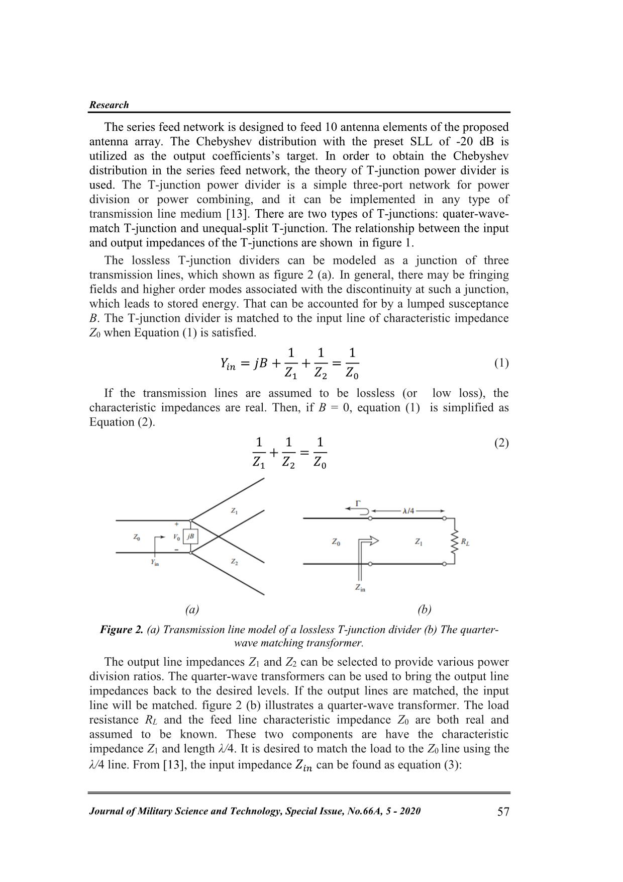
λ/4 line. From [13], the input impedance 𝑖𝑛 can be found as equation (3):
Electronics & Automation
N. T. K. Ngan, , L. M. Thuy, “Series feed fan-beam antenna  positioning system.” 58
 𝑖𝑛 = 1 (
𝑅𝐿 + 𝑗 1 tan𝛽𝑙
 1 + 𝑗𝑅𝐿 tan𝛽𝑙
)
(3)
If l = 𝜆 4 then 𝛽𝑙 = 𝜋 𝜆 𝜆 4 = 𝜋 , which leads to:
 𝑖𝑛 =
 1
2
𝑅𝐿
(4)
Let ᴦ reachs the minimum value, then 𝑖𝑛 = 0 and :
 1 = √ 0 𝐿 (5)
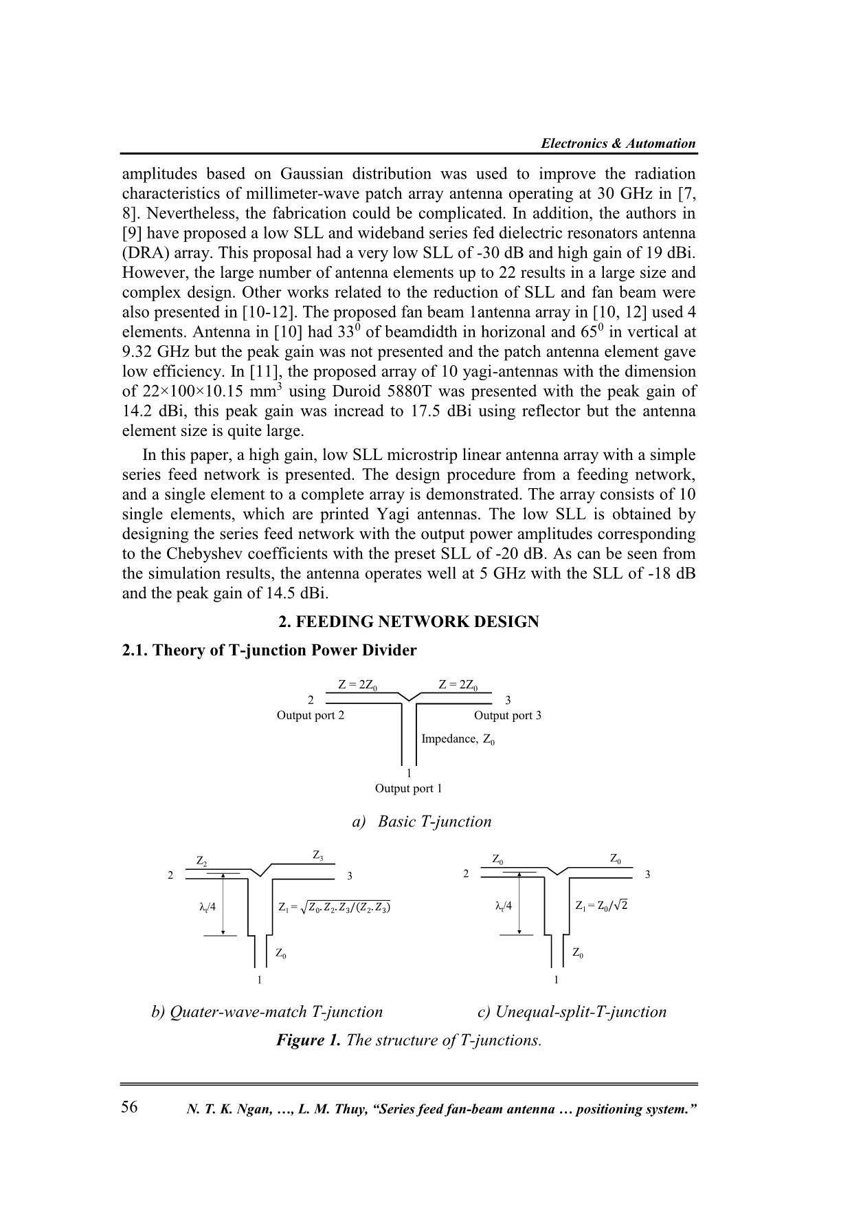
So a quarter-wave-matched-T Junction with Z0 = 50 ohm input impedance and
two equal output ports of Z0 = 50 ohm, the impedance of the quarter-wave-
transformer is determined by equation (7):
 1 = 0 √ (7)
2.2. Feeding Network Design
In this paper, the Chebyshev distribution is applied to calculate the output
power amplitude for each element in the array [2]. The 1-10 feeding network
consists of a main line fed by the 50 Ω line at the center, unequal T-junctions to
control the output power amplitude excited at each the element and quarter-wave–
transformers to be matched with antenna element impedance. The Chebyshev
output power amplitudes for 10 antenna elements are calculated and listed in the
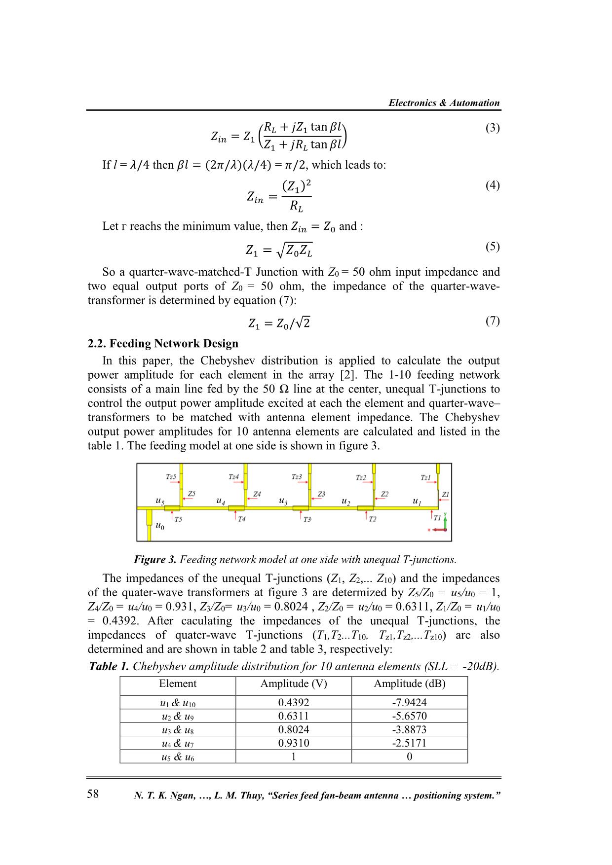
table 1. The feeding model at one side is shown in figure 3.
 Figure 3. Feeding network model at one side with unequal T-junctions.
The impedances of the unequal T-junctions (Z1, Z2,... Z10) and the impedances
of the quater-wave transformers at figure 3 are determized by Z5/Z0 = u5/u0 = 1,
Z4/Z0 = u4/u0 = 0.931, Z3/Z0= u3/u0 = 0.8024 , Z2/Z0 = u2/u0 = 0.6311, Z1/Z0 = u1/u0
= 0.4392. After caculating the impedances of the unequal T-junctions, the
impedances of quater-wave T-junctions (T1,T2...T10, Tz1,Tz2,...Tz10) are also
determined and are shown in table 2 and table 3, respectively:
Table 1. Chebyshev amplitude distribution for 10 antenna elements (SLL = -20dB).
Element Amplitude (V) Amplitude (dB)
u1 & u10 0.4392 -7.9424
u2 & u9 0.6311 -5.6570
u3 & u8 0.8024 -3.8873
u4 & u7 0.9310 -2.5171
u5 & u6 1 0
u0
u5 u4 u3 u2 u1
Research
Journal of Military Science and Technology, Special Issue, No.66A, 5 - 2020 59
Table 2. Impedance and dimension of T-Junctions.
Feed element Amplitude (V) Impedance (Ω) Value of width (mm)
Z1 & Z10 0.4392 113.84 0.28
Z2 & Z9 0.6311 79.227 0.75
Z3 & Z8 0.8024 62.313 1.2
Z4 & Z7 0.9311 53.706 1.58
Z5 & Z6 1 50 1.75
Table 3. Dimension of the quarter-wave –transformers.
Transformer Value of width
(mm)
Transformer Value of width
(mm)
T1 2.98 Tz1 1.75
T2 2.924 Tz2 1.68
T3 2.77 Tz3 1.48
T4 2.58 Tz4 1.19
T5 0.8343 Tz5 0.8343
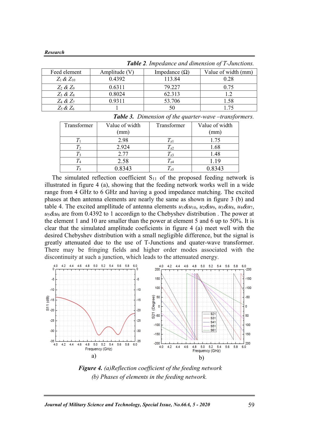
The simulated reflection coefficient S11 of the proposed feeding network is
illustrated in figure 4 (a), showing that the feeding network works well in a wide
range from 4 GHz to 6 GHz and having a good impedance matching. The excited
phases at then antenna elements are nearly the same as shown in figure 3 (b) and
table 4. The excited ampllitude of antenna elements u1&u10, u2&u9, u3&u8, u4&u7,
u5&u6 are from 0.4392 to 1 accordign to the Chebyshev distribution . The power at
the element 1 and 10 are smaller than the power at element 5 and 6 up to 50%. It is
clear that the simulated amplitude coeficients in figure 4 (a) meet well with the
desired Chebyshev distribution with a small negligible difference, but the signal is
greatly attenuated due to the use of T-Junctions and quater-wave transformer.
There may be fringing fields and higher order modes associated with the
discontinuity at such a junction, which leads to the attenuated energy.
a) b)
 Figure 4. (a)Reflection coefficient of the feeding network
(b) Phases of elements in the feeding network.
Electronics & Automation
N. T. K. Ngan, , L. M. Thuy, “Series feed fan-beam antenna  positioning system.” 60
3. THE PROPOSED ARRAY ANTENNA
3.1. Printed Yagi Antenna Element
 The printed Yagi antenna originated from the Yagi-Uda antenna by Huang in
1991 [14] is chosen in this paper. Its structure consists of a folded half-wavelength
dipole and an approximately quater-wavelength rectangular director to improve the
gain and the front-to-back ratio. Besides, it is low profile, low-cost and has light
weight, small size. These advantages make it suitable to be integrated into circuits
as well as to be easily fabricated. Many contributions have been done in the design
and optimization of the printed Yagi-antenna for specific applications [15-17]. In
[13], the Invasive Weed Optimization (IWO) method is applied to design and
optimize a printed Yagi antenna, the optimization goals are set to reach an antenna
with a VSWR less than 1.5 and high gain radiation pattern. PSO (Particle swarm
optimization) has been used to optimize gain, impedance and bandwidth of Yagi–
Uda array in [16]. In our proposal, two directors are used to increase the
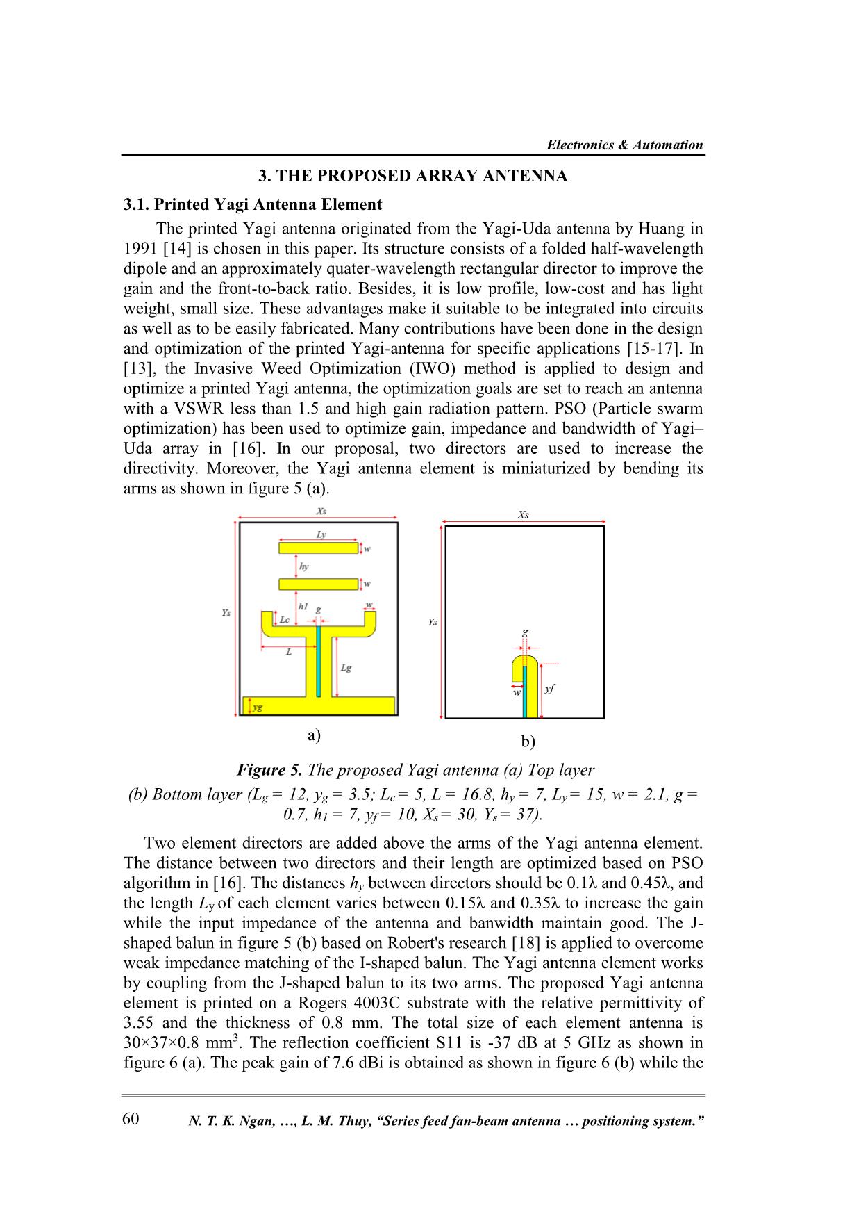
directivity. Moreover, the Yagi antenna element is miniaturized by bending its
arms as shown in figure 5 (a).
 a)
 b)
 Figure 5. The proposed Yagi antenna (a) Top layer
(b) Bottom layer (Lg = 12, yg = 3.5; Lc = 5, L = 16.8, hy = 7, Ly = 15, w = 2.1, g =
0.7, h1 = 7, yf = 10, Xs = 30, Ys = 37).
Two element directors are added above the arms of the Yagi antenna element.
The distance between two directors and their length are optimized based on PSO
algorithm in [16]. The distances hy between directors should be 0.1λ and 0.45λ, and
the length Ly of each element varies between 0.15λ and 0.35λ to increase the gain
while the input impedance of the antenna and banwidth maintain good. The J-
shaped balun in figure 5 (b) based on Robert's research [18] is applied to overcome
weak impedance matching of the I-shaped balun. The Yagi antenna element works
by coupling from the J-shaped balun to its two arms. The proposed Yagi antenna
element is printed on a Rogers 4003C substrate with the relative permittivity of
3.55 and the thickness of 0.8 mm. The total size of each element antenna is
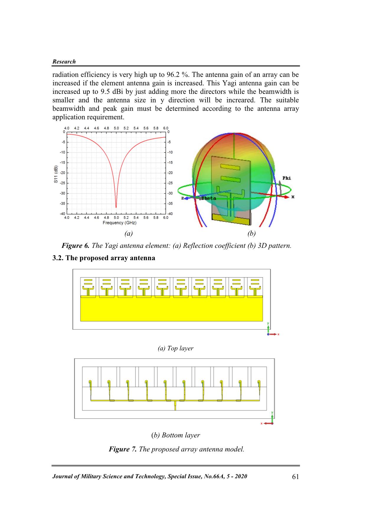
30×37×0.8 mm3. The reflection coefficient S11 is -37 dB at 5 GHz as shown in
figure 6 (a). The peak gain of 7.6 dBi is obtained as shown in figure 6 (b) while the
Research
Journal of Military Science and Technology, Special Issue, No.66A, 5 - 2020 61
radiation efficiency is very high up to 96.2 %. The antenna gain of an array can be
increased if the element antenna gain is increased. This Yagi antenna gain can be
increased up to 9.5 dBi by just adding more the directors while the beamwidth is
smaller and the antenna size in y direction will be increared. The suitable
beamwidth and peak gain must be determined according to the antenna array
application requirement.
 (a) (b)
 Figure 6. The Yagi antenna element: (a) Reflection coefficient (b) 3D pattern.
3.2. The proposed array antenna
(a) Top layer
(b) Bottom layer
 Figure 7. The proposed array antenna model.
Electronics & Automation
N. T. K. Ngan, , L. M. Thuy, “Series feed fan-beam antenna  positioning system.” 62
The array structure is created by combining 10 single elements and 1-10 series
feed network designed in the previous sections as shown in figure 7. The distance
between the elements in the antenna array is λ, and the overall size of
450×57×0.8 mm3.
Table 4. Phase and amplitude excitation of the proposed array.
Element Phase (degree) Amplitude (dB)
u1 & u10 126 -16
u2 & u9 125.5 -14
u3 & u8 126 -13
u4 & u7 130 -9
u5 & u6 135 -6
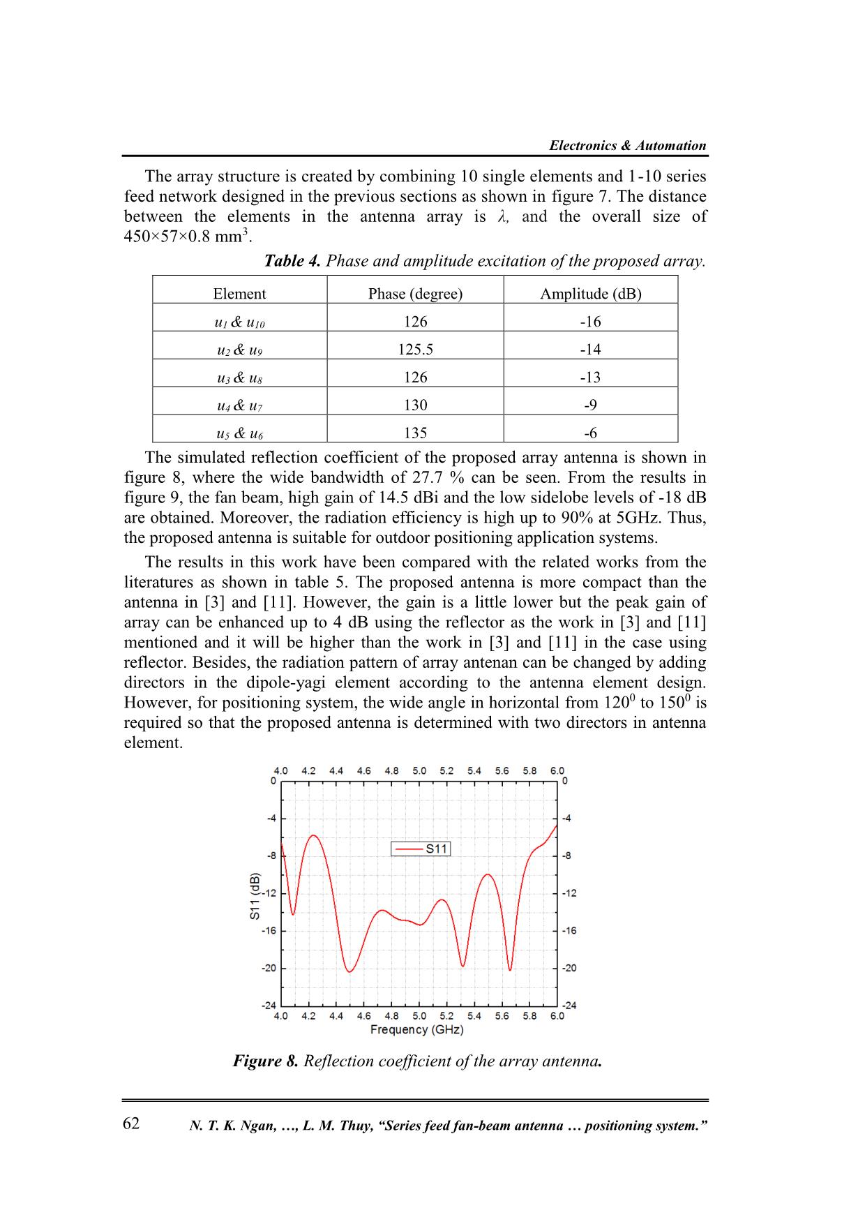
The simulated reflection coefficient of the proposed array antenna is shown in
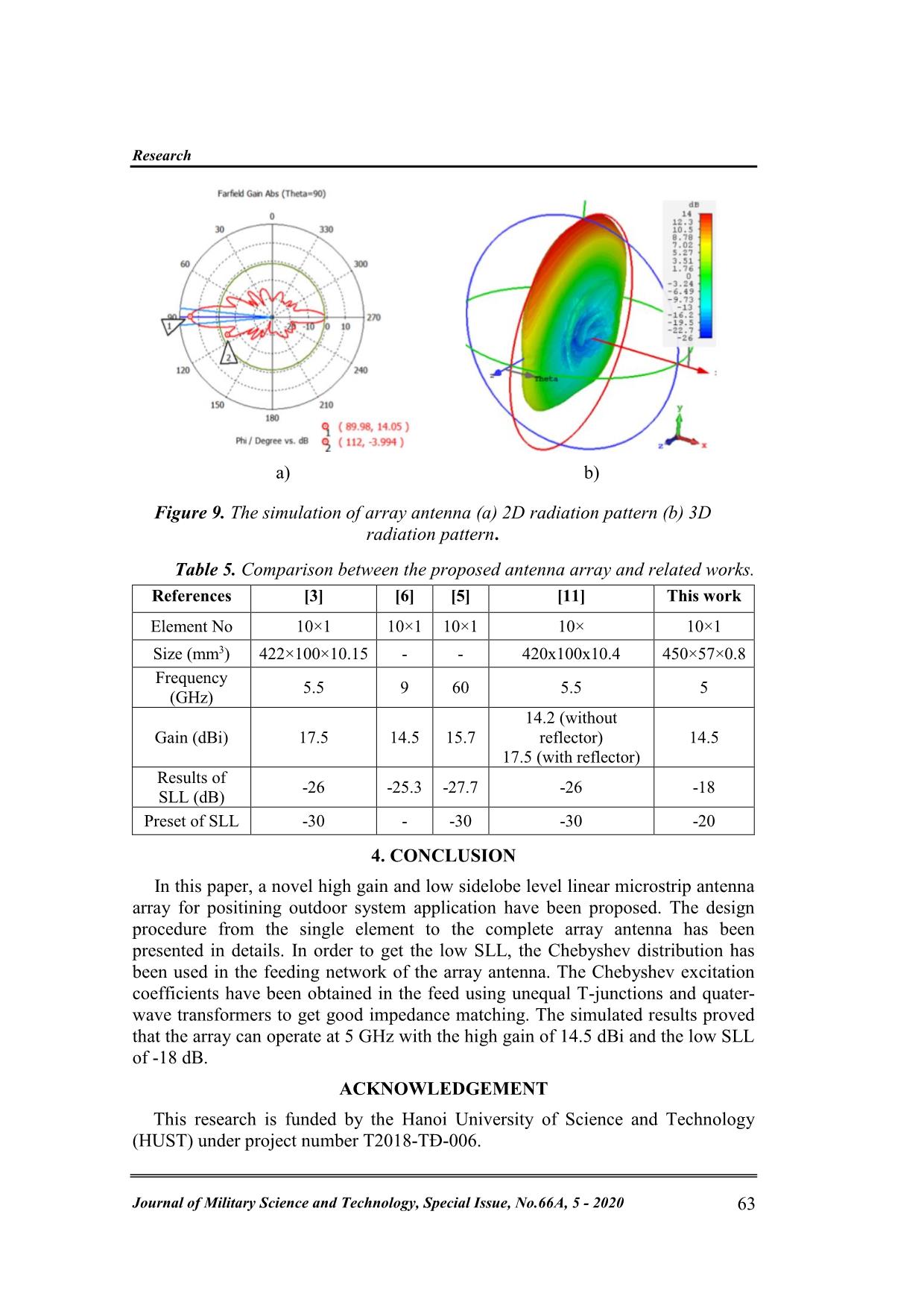
figure 8, where the wide bandwidth of 27.7 % can be seen. From the results in
figure 9, the fan beam, high gain of 14.5 dBi and the low sidelobe levels of -18 dB
are obtained. Moreover, the radiation efficiency is high up to 90% at 5GHz. Thus,
the proposed antenna is suitable for outdoor positioning application systems.
The results in this work have been compared with the related works from the
literatures as shown in table 5. The proposed antenna is more compact than the
antenna in [3] and [11]. However, the gain is a little lower but the peak gain of
array can be enhanced up to 4 dB using the reflector as the work in [3] and [11]
mentioned and it will be higher than the work in [3] and [11] in the case using
reflector. Besides, the radiation pattern of array antenan can be changed by adding
directors in the dipole-yagi element according to the antenna element design.
However, for positioning system, the wide angle in horizontal from 1200 to 1500 is
required so that the proposed antenna is determined with two directors in antenna
element.
 Figure 8. Reflection coefficient of the array antenna.
Research
Journal of Military Science and Technology, Special Issue, No.66A, 5 - 2020 63
a)
b)
Figure 9. The simulation of array antenna (a) 2D radiation pattern (b) 3D
radiation pattern.
Table 5. Comparison between the proposed antenna array and related works.
References [3] [6] [5] [11] This work
Element No 10×1 10×1 10×1 10× 10×1
Size (mm3) 422×100×10.15 - - 420x100x10.4 450×57×0.8
Frequency
(GHz)
5.5 9 60 5.5 5
Gain (dBi) 17.5 14.5 15.7
14.2 (without
reflector)
17.5 (with reflector)
14.5
Results of
SLL (dB)
-26 -25.3 -27.7 -26 -18
Preset of SLL -30 - -30 -30 -20
4. CONCLUSION
In this paper, a novel high gain and low sidelobe level linear microstrip antenna
array for positining outdoor system application have been proposed. The design
procedure from the single element to the complete array antenna has been
presented in details. In order to get the low SLL, the Chebyshev distribution has
been used in the feeding network of the array antenna. The Chebyshev excitation
coefficients have been obtained in the feed using unequal T-junctions and quater-
wave transformers to get good impedance matching. The simulated results proved
that the array can operate at 5 GHz with the high gain of 14.5 dBi and the low SLL
of -18 dB.
ACKNOWLEDGEMENT
This research is funded by the Hanoi University of Science and Technology
(HUST) under project number T2018-TĐ-006.
Electronics & Automation
N. T. K. Ngan, , L. M. Thuy, “Series feed fan-beam antenna  positioning system.” 64
REFERENCES
[1]. D. Ehyaie, “Novel Approaches to the Design of Phased Array Antennas,” Jan. 2011.
[2]. C. A. Balanis, Antenna theory: analysis and design, Chapter 7, 3rd ed. Hoboken, NJ:
John Wiley, 2005.
[3]. T. Toan, T. Nguyen, and T. Giang, A low sidelobe fan-beam series fed linear
antenna array for IEEE 802.11ac outdoor applications. 2017 International
Conference on Advanced Technologies for Communications (ATC), pp. 161-165.
[4]. D. M. Pozar and B. Kaufman, “Design considerations for low sidelobe microstrip
arrays,” IEEE Trans. Antennas Propag., vol. 38, no. 8, pp. 1176–1185, Aug. 1990.
[5]. Wenhui Shen, Jiahong Lin, and Kang Yang, “Design of a V-band low sidelobe and
wideband linear DRA array,” 2016, pp. 477–480.
[6]. J. Yin, Q. Wu, C. Yu, H. Wang, and W. Hong, “Low-Sidelobe-Level Series-Fed
Microstrip Antenna Array of Unequal Interelement Spacing,” IEEE Antennas Wirel.
Propag. Lett., vol. 16, pp. 1695–1698, 2017.
[7]. M. Dürr, A. Trastoy, and F. Ares, “Multiple-pattern linear antenna arrays with
single prefixed amplitude distributions: modified Woodward-Lawson synthesis,”
Electron. Lett., vol. 36, no. 16, p. 1345, 2000.
[8]. M. F. A. Ahmed, O. M. Haraz, G. Kaddoum, S. A. Alshebili, and A.-R. Sebak, “On
using Gaussian excitation amplitudes to improve the antenna array radiation
characteristics,” 2014 IEEE Asia-Pacific Conference on Applied Electromagnetics
(APACE), pp. 131–134.
[9]. J. Lin, W. Shen, and K. Yang, “A Low-Sidelobe and Wideband Series-Fed Linear
Dielectric Resonator Antenna Array,” IEEE Antennas Wirel. Propag. Lett., vol. 16,
pp. 513–516, 2017.
[10]. P. Borah and S. Bhattacharyya, "Design of a fan beam 1×4 array antenna using V-
shaped patch element for its use in X-band communication," URSI AP-RASC 2019,
New Delhi, India, 09 - 15 March 2019.
[11]. Tang The Toan, Nguyen Minh Tran and Truong Vu Bang Giang, "A Novel
Chebyshev Series Fed Linear Array with High Gain and Low Sidelobe Level for
WLAN Outdoor Systems," REV Journal on Electronics and Communications, Vol. 8,
No. 1–2, January–June, 2018.
[12]. Sun-Woong Kim and Dong-You Choi, "Analysis of Beamforming Antenna for
Practical Indoor Location-Tracking Application," Journal of Sensors,
doi:10.3390/s19143040, 2019
[13]. D. M. Pozar, "Microwave engineering," Chapter 7, 4th ed. Hoboken, NJ:
Wiley, 2012
 [14]. J. Huang and A. C. Densmore, “Microstrip Yagi array antenna for mobile satellite
vehicle application,” IEEE Trans. Antennas Propag., vol. 39, no. 7, pp. 1024–1030,
Jul. 1991.
[15]. S. H. Sedighy, A. R. Mallahzadeh, M. Soleimani, and J. Rashed-Mohassel,
“Optimization of Printed Yagi Antenna Using Invasive Weed Optimization (IWO),”
IEEE Antennas Wirel. Propag. Lett., vol. 9, pp. 1275–1278, 2010.
[16]. M. Rattan, M. S. Patterh, and B. S. Sohi, “Optimization of Gain, Impedance, and
Bandwidth of Yagi-Uda Array Using Particle Swarm Optimization,” Int. J. Antennas
Propag., vol. 2008, pp. 1–4, 2008.
Research
Journal of Military Science and Technology, Special Issue, No.66A, 5 - 2020 65
[17]. J.-M. Floc H and A. El Sayed Ahmad, “Dual-Band Printed Dipole Antenna with
Parasitic Element for Compensation of Frequency Space Attenuation,” Int. J.
Electromagn. Appl., vol. 2, no. 5, pp. 120–128, Dec. 2012.
[18]. Trong Thuy Pham, Le Minh Thuy, Tran Truong Phan, Pham Xuan Lap, Ngo Hoang
Anh, “Novel Dual-Polarized 5G Base Station Antenna”, 2017 IEEE Asia Pacific
Microwave Conference (APMC), pp 474-478, (2019).
TÓM TẮT
ĂNG TEN MẢNG TUYẾN TÍNH TIẾP ĐIỆN NỐI TIẾP BÚP SÓNG DẢI
QUẠT VỚI MỨC BÚP PHỤ THẤP CHO HỆ THỐNG ĐỊNH VỊ
Bài báo này đề xuất một mảng ăng ten mới hoạt động ở dải tần 5 GHz với búp
sóng phụ thấp phù hợp cho các ứng dụng định vị ngoài trời. Mảng ăng ten có kích
thước nhỏ gọn 450 ×57×0.8 mm3 gồm 10 phần tử, độ tăng ích 14.5 dBi và độ nén
búp phụ thấp -18 dB tại tần số 5 GHz. Ẳng-ten sử dụng mạng tiếp điện 1-10 kiểu nối
tiếp, phân bố biên độ ở các đầu ra tuân theo luật phân phối Chebyshev để đạt độ
nén búp sóng phụ thấp. Các ăng ten chấn tử Yagi kiểu mạch in được sử dụng để
tăng tính định hướng cho ăng ten mảng. Ngoài ra, độ tăng ích của ăng ten phần tử
có thể được tăng bằng việc ghép thêm phần tử dẫn sóng định hướng phía trên các
ăng-ten chấn tử.
Từ khóa: Mảng ăng-ten vi dải; Độ nén búp sóng phụ thấp; Đa thức Chebyshev; Ăng-ten Yagi vi dải.
Received 20th February, 2020
Revised 11th April, 2020
Published 06th May, 2020
Author affiliations:
1 Hanoi University of Science and Technology;
2 Electric Power University;
3 University of Transport and Communications.
*Corresponding author: thuy.lm@hust.edu.vn.
File đính kèm:
 series_feed_fan_beam_antenna_array_with_a_low_sidelobe_level.pdf

