PR Current Controllers for Harmonics Generators to Test an Inductive Current Transformer
Current transformers are commonly used electrical devices to measure the current of electric loads. To
assess the quality and accuracy of the current transformer, one of the necessary requirements is to evaluate
the accuracy of this object under the condition that the primary current has a large distorted waveform and is
composed of harmonics. This has led to the need to create a programmable current source capable of
generating current that contains basic harmonic components and high harmonics according to present
standards. The current source must accurately generate the desired amplitude and frequency values, which
in turn requires the use of resonant modulation regulators. The parameters of the regulator greatly affect the
quality of the above current source. Therefore, this article will present a method of calculating the
proportional-resonant regulator parameter, corresponding to each generated harmonic component.
Simulation results performed in MATLAB software have proven effective design methods when applying the
generated harmonic components. Experiment results will be discussed in detail for such an advanced
regulator.
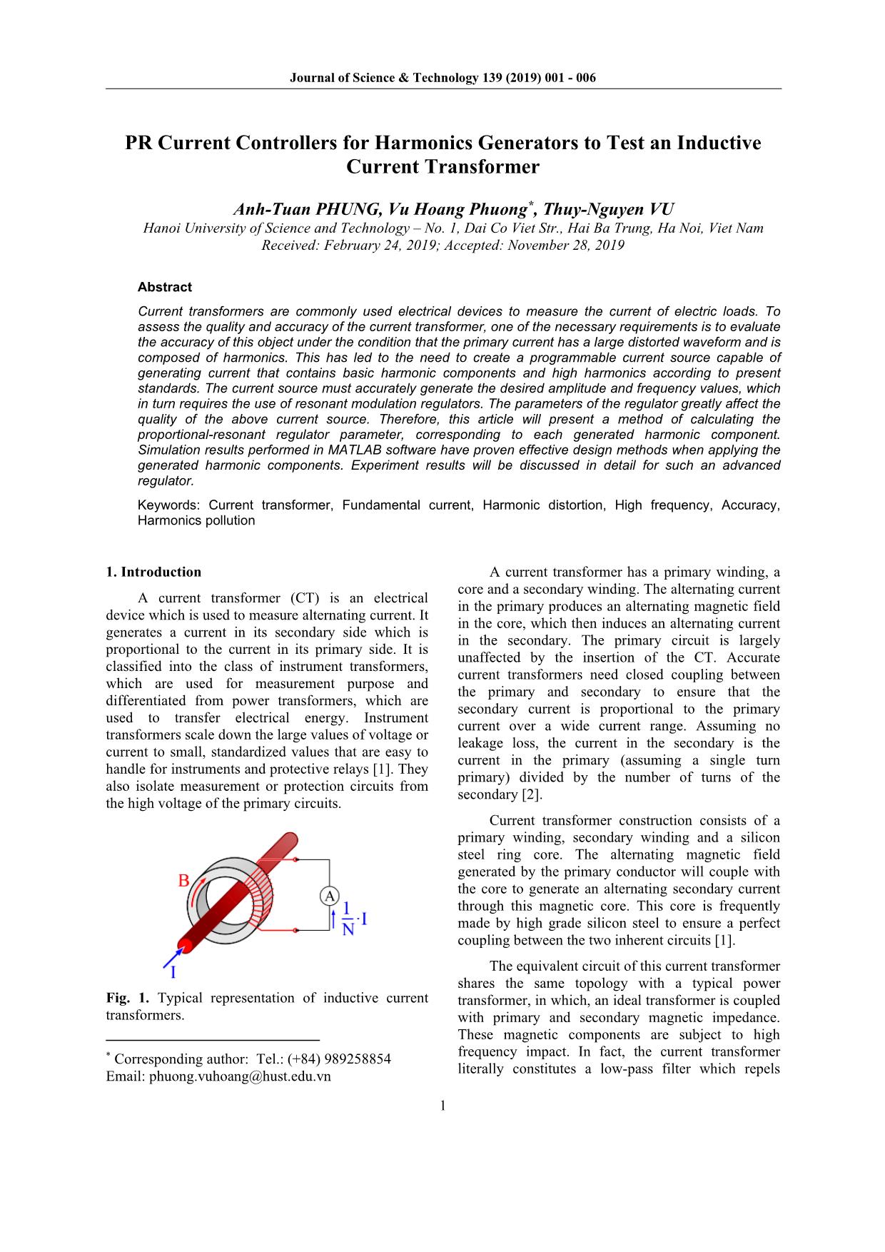
Trang 1
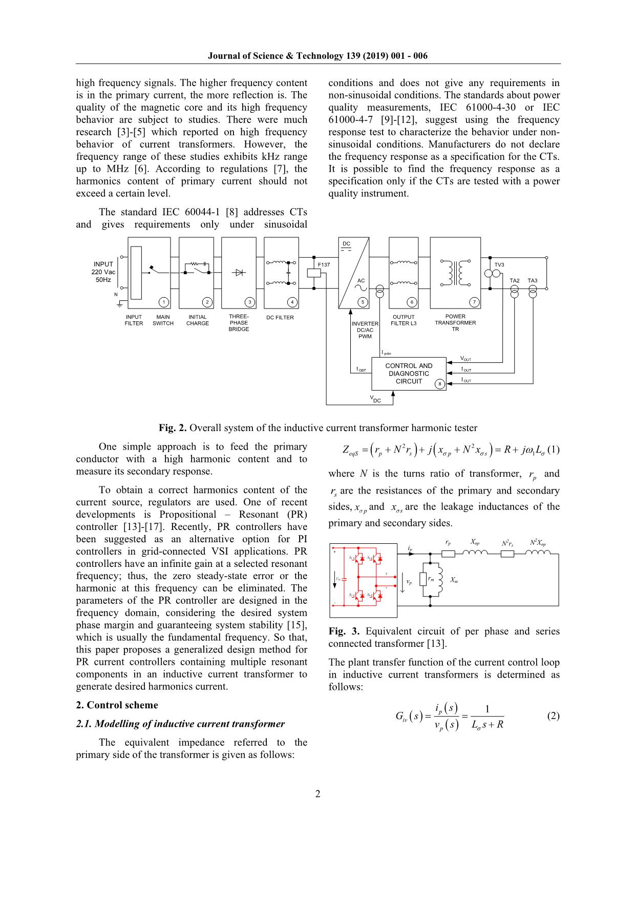
Trang 2
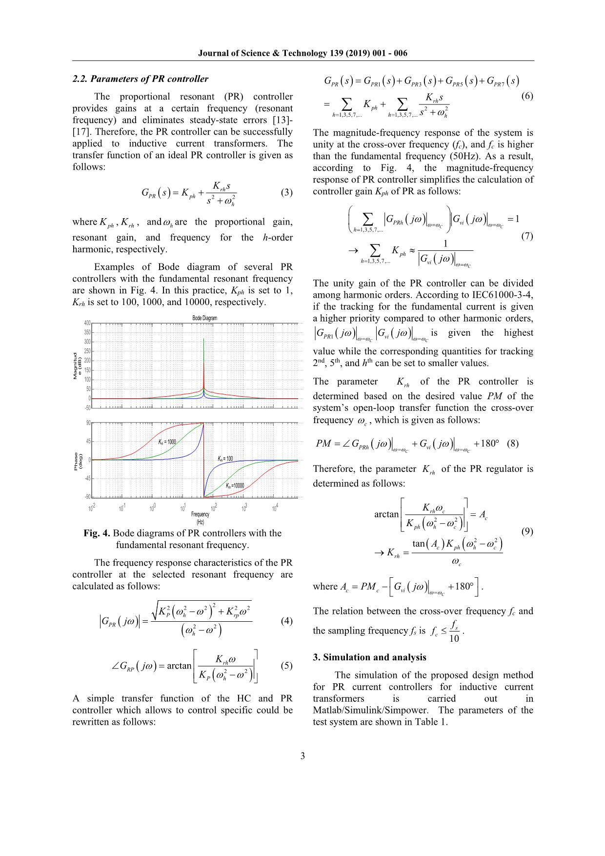
Trang 3
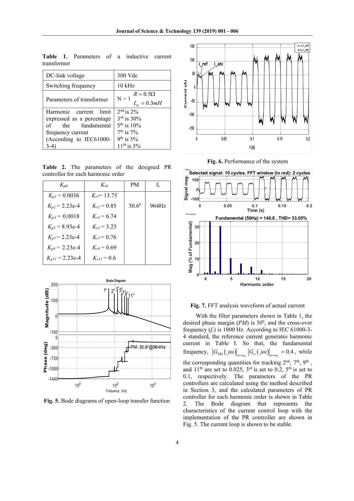
Trang 4
Trang 5
Trang 6
Tóm tắt nội dung tài liệu: PR Current Controllers for Harmonics Generators to Test an Inductive Current Transformer
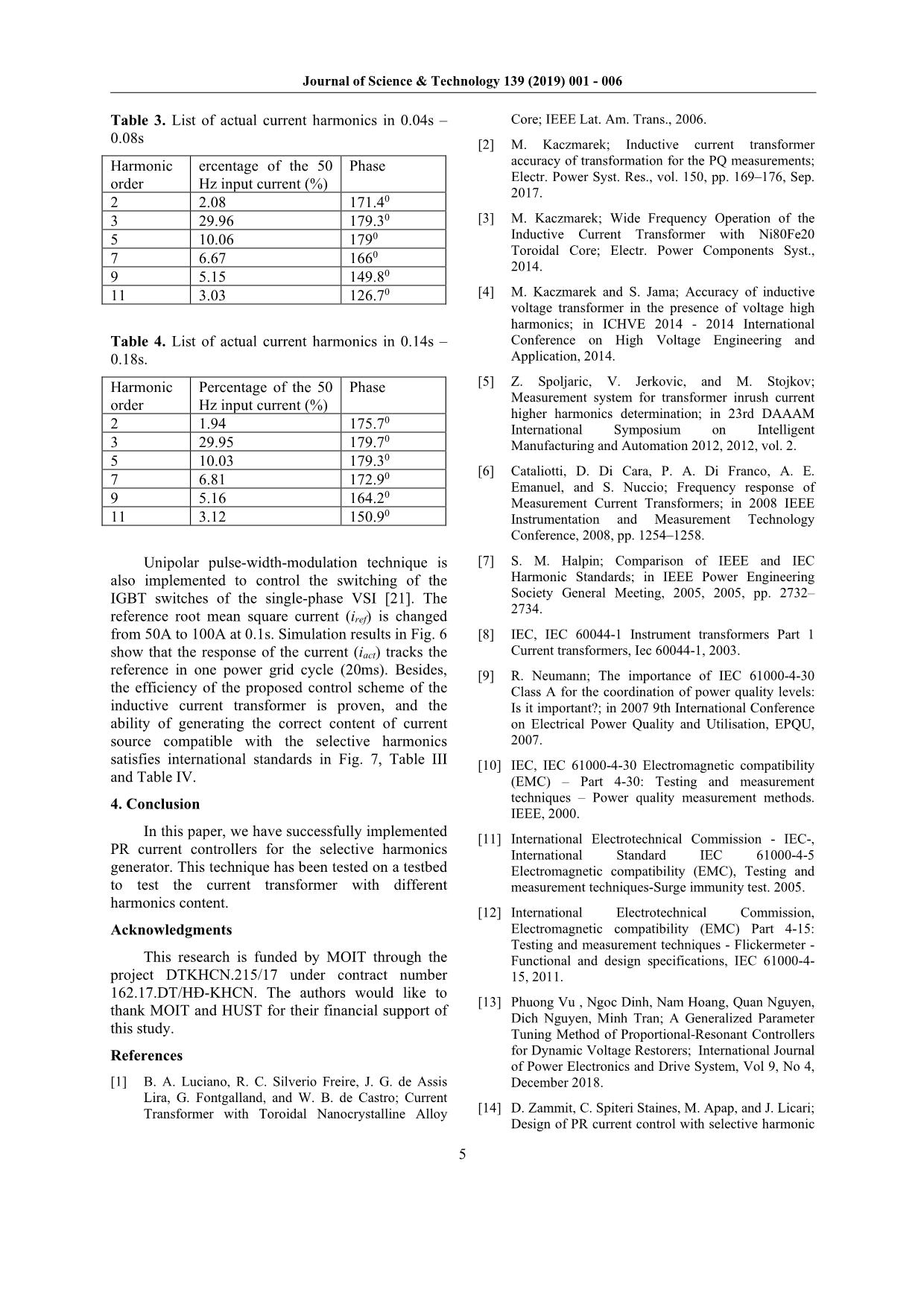
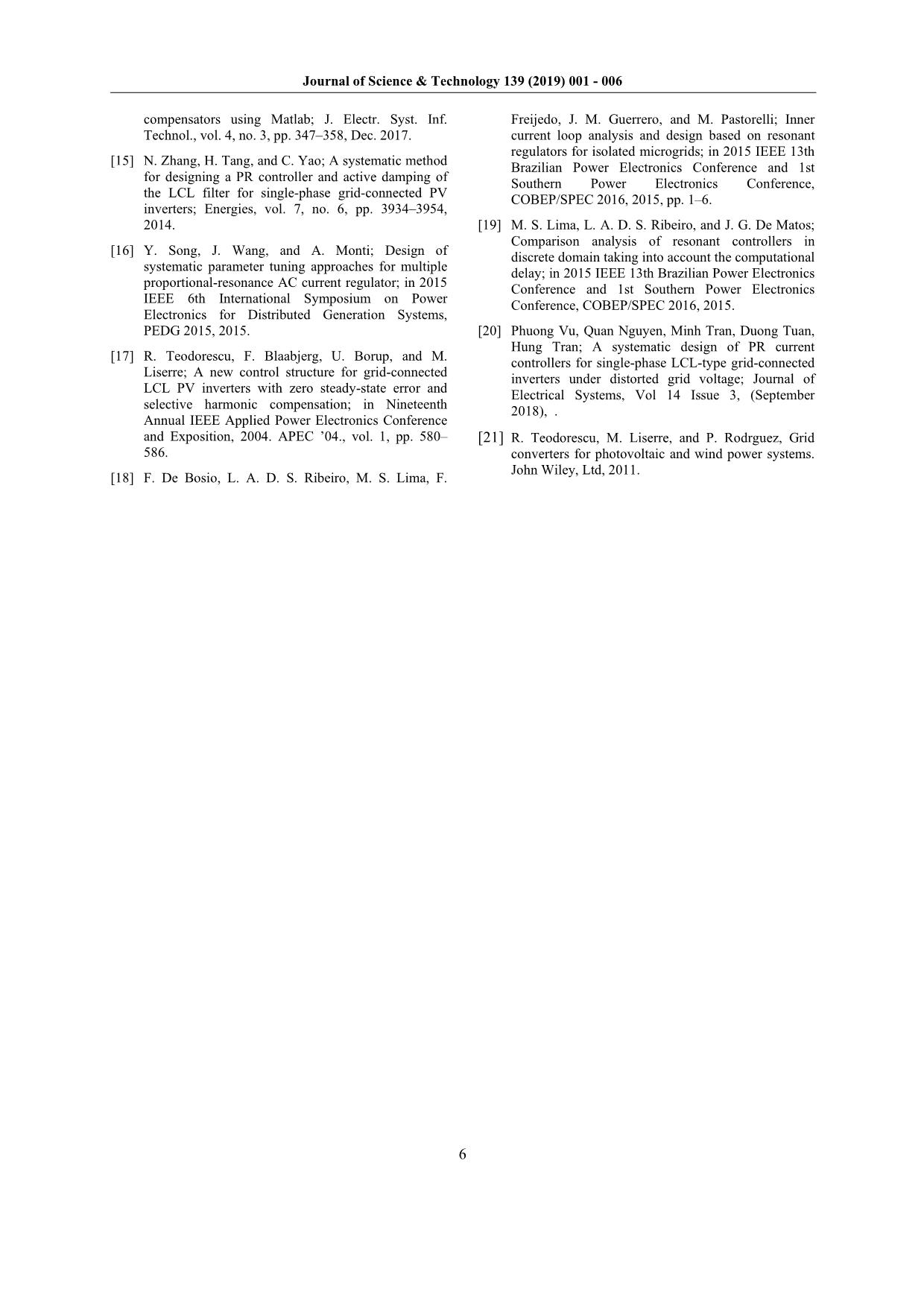
According to regulations [7], the harmonics content of primary current should not exceed a certain level. The standard IEC 60044-1 [8] addresses CTs and gives requirements only under sinusoidal conditions and does not give any requirements in non-sinusoidal conditions. The standards about power quality measurements, IEC 61000-4-30 or IEC 61000-4-7 [9]-[12], suggest using the frequency response test to characterize the behavior under non- sinusoidal conditions. Manufacturers do not declare the frequency response as a specification for the CTs. It is possible to find the frequency response as a specification only if the CTs are tested with a power quality instrument. 1 N INPUT 220 Vac 50Hz 2 CONTROL AND DIAGNOSTIC CIRCUIT INPUT FILTER MAIN SWITCH INITIAL CHARGE THREE- PHASE BRIDGE DC FILTER INVERTER DC/AC PWM F137 DC OUTPUT FILTER L3 POWER TRANSFORMER TR TV3 TA2 TA3AC 3 4 5 6 7 8 VDC VOUT I OUT I OUT I GBT I prim Fig. 2. Overall system of the inductive current transformer harmonic tester One simple approach is to feed the primary conductor with a high harmonic content and to measure its secondary response. To obtain a correct harmonics content of the current source, regulators are used. One of recent developments is Propositional – Resonant (PR) controller [13]-[17]. Recently, PR controllers have been suggested as an alternative option for PI controllers in grid-connected VSI applications. PR controllers have an infinite gain at a selected resonant frequency; thus, the zero steady-state error or the harmonic at this frequency can be eliminated. The parameters of the PR controller are designed in the frequency domain, considering the desired system phase margin and guaranteeing system stability [15], which is usually the fundamental frequency. So that, this paper proposes a generalized design method for PR current controllers containing multiple resonant components in an inductive current transformer to generate desired harmonics current. 2. Control scheme 2.1. Modelling of inductive current transformer The equivalent impedance referred to the primary side of the transformer is given as follows: ( ) ( )2 2 1eqS p s p sZ r N r j x N x R j Lσ σ σω= + + + = + (1) where N is the turns ratio of transformer, pr and sr are the resistances of the primary and secondary sides, px and sx are the leakage inductances of the primary and secondary sides. Xmrm Xσp N2rs N 2Xσp S4 S1 S2 S3 Udc + - - + vp ip rp Fig. 3. Equivalent circuit of per phase and series connected transformer [13]. The plant transfer function of the current control loop in inductive current transformers is determined as follows: ( ) ( ) ( ) 1p iv p i s G s v s L s Rσ = = + (2) Journal of Science & Technology 139 (2019) 001 - 006 3 2.2. Parameters of PR controller The proportional resonant (PR) controller provides gains at a certain frequency (resonant frequency) and eliminates steady-state errors [13]- [17]. Therefore, the PR controller can be successfully applied to inductive current transformers. The transfer function of an ideal PR controller is given as follows: ( ) 2 2rhPR ph h K s G s K s ω = + + (3) where phK , rhK , and hω are the proportional gain, resonant gain, and frequency for the h-order harmonic, respectively. Examples of Bode diagram of several PR controllers with the fundamental resonant frequency are shown in Fig. 4. In this practice, Kph is set to 1, Krh is set to 100, 1000, and 10000, respectively. -50 0 50 100 150 200 250 300 350 400 M a g n it u d e ( d B ) -90 -45 0 45 90 P h a s e (d e g ) Bode Diagram 10-2 10-1 100 101 102 103 104 Frequency (Hz) Krh = 100 Krh = 1000 Krh =10000 Fig. 4. Bode diagrams of PR controllers with the fundamental resonant frequency. The frequency response characteristics of the PR controller at the selected resonant frequency are calculated as follows: ( ) ( ) ( ) 22 2 2 2 2 2 2 P h rp PR h K K G j ω ω ω ω ω ω − + = − (4) ( ) ( )2 2 arctan rhRP P h K G j K ω ω ω ω ∠ = − (5) A simple transfer function of the HC and PR controller which allows to control specific could be rewritten as follows: ( ) ( ) ( ) ( ) ( )1 3 5 7 2 2 1,3,5,7,... 1,3,5,7,... PR PR PR PR PR rh ph h h h G s G s G s G s G s K s K s ω= = = + + + = + +∑ ∑ (6) The magnitude-frequency response of the system is unity at the cross-over frequency (fc), and fc is higher than the fundamental frequency (50Hz). As a result, according to Fig. 4, the magnitude-frequency response of PR controller simplifies the calculation of controller gain Kph of PR as follows: ( ) ( ) ( ) 1,3,5,7,... 1,3,5,7,... 1 1 C C C PRh vi h ph h vi G j G j K G j ω ω ω ω ω ω ω ω ω = = = = = = → ≈ ∑ ∑ (7) The unity gain of the PR controller can be divided among harmonic orders. According to IEC61000-3-4, if the tracking for the fundamental current is given a higher priority compared to other harmonic orders, ( ) ( )1 C C PR viG j G jω ω ω ωω ω= = is given the highest value while the corresponding quantities for tracking 2nd, 5th, and hth can be set to smaller values. The parameter rhK of the PR controller is determined based on the desired value PM of the system’s open-loop transfer function the cross-over frequency cω , which is given as follows: ( ) ( ) 180 C C PRh viPM G j G jω ω ω ωω ω= == ∠ + + ° (8) Therefore, the parameter rhK of the PR regulator is determined as follows: ( ) ( ) ( ) 2 2 2 2 arctan tan rh c c ph h c c ph h c rh c K A K A K K ω ω ω ω ω ω = − − → = (9) where ( ) 180 C c c viA PM G j ω ωω = = − + ° . The relation between the cross-over frequency fc and the sampling frequency fs is 10 s c f f ≤ . 3. Simulation and analysis The simulation of the proposed design method for PR current controllers for inductive current transformers is carried out in Matlab/Simulink/Simpower. The parameters of the test system are shown in Table 1. Journal of Science & Technology 139 (2019) 001 - 006 4 Table 1. Parameters of a inductive current transformer DC-link voltage 300 Vdc Switching frequency 10 kHz Parameters of transformer N = 1 0.5 0.3 R L mHσ = Ω = Harmonic current limit expressed as a percentage of the fundamental frequency current (According to IEC61000- 3-4) 2nd is 2% 3rd is 30% 5th is 10% 7th is 7% 9th is 5% 11th is 3% Table 2. The parameters of the designed PR controller for each harmonic order Kph Krh PM fc Kp1 = 0.0036 Kp2 = 2.23e-4 Kp3 = 0.0018 Kp5 = 8.93e-4 Kp7 = 2.23e-4 Kp9 = 2.23e-4 Kp11 = 2.23e-4 Kr1= 13.75 Kr2 = 0.85 Kr3 = 6.74 Kr5 = 3.23 Kr7 = 0.76 Kr9 = 0.69 Kr11 = 0.6 30.60 964Hz -100 0 100 200 M ag n it u d e (d B ) 100 102 104 -1440 -1080 -720 -360 0 P h as e (d eg ) Bode Diagram Frequency (Hz) PM: 30.6º@964Hz 1st 2st 3 st 5st 9st7 st 11st Fig. 5. Bode diagrams of open-loop transfer function 0 0.05 0.1 0.15 0.2 t (s) -150 -100 -50 0 50 100 150 C u rr e n t (A ) i_ref I_atc i_ref i_atc i_ref i_atc Fig. 6. Performance of the system Signal 0 0.05 0.1 0.15 0.2 Time (s) -100 0 100 Si gn al m ag . Selected signal: 10 cycles. FFT window (in red): 2 cycles FFT analysis 0 5 10 15 20 Harmonic order 0 10 20 30 M ag (% of Fu nd am en ta l) Fundamental (50Hz) = 140.8 , THD= 33.05% Fig. 7. FFT analysis waveform of actual current With the filter parameters shown in Table 1, the desired phase margin (PM) is 300, and the cross-over frequency (fc) is 1000 Hz. According to IEC 61000-3- 4 standard, the reference current generates harmonic current in Table I. So that, the fundamental frequency, ( ) ( )1 0.4 C C PR viG j G jω ω ω ωω ω= = = , while the corresponding quantities for tracking 2nd, 7th, 9th , and 11th are set to 0.025, 3rd is set to 0.2, 5th is set to 0.1, respectively. The parameters of the PR controllers are calculated using the method described in Section 3, and the calculated parameters of PR controller for each harmonic order is shown in Table 2. The Bode diagram that represents the characteristics of the current control loop with the implementation of the PR controller are shown in Fig. 5. The current loop is shown to be stable. Journal of Science & Technology 139 (2019) 001 - 006 5 Table 3. List of actual current harmonics in 0.04s – 0.08s Harmonic order ercentage of the 50 Hz input current (%) Phase 2 2.08 171.40 3 29.96 179.30 5 10.06 1790 7 6.67 1660 9 5.15 149.80 11 3.03 126.70 Table 4. List of actual current harmonics in 0.14s – 0.18s. Harmonic order Percentage of the 50 Hz input current (%) Phase 2 1.94 175.70 3 29.95 179.70 5 10.03 179.30 7 6.81 172.90 9 5.16 164.20 11 3.12 150.90 Unipolar pulse-width-modulation technique is also implemented to control the switching of the IGBT switches of the single-phase VSI [21]. The reference root mean square current (iref) is changed from 50A to 100A at 0.1s. Simulation results in Fig. 6 show that the response of the current (iact) tracks the reference in one power grid cycle (20ms). Besides, the efficiency of the proposed control scheme of the inductive current transformer is proven, and the ability of generating the correct content of current source compatible with the selective harmonics satisfies international standards in Fig. 7, Table III and Table IV. 4. Conclusion In this paper, we have successfully implemented PR current controllers for the selective harmonics generator. This technique has been tested on a testbed to test the current transformer with different harmonics content. Acknowledgments This research is funded by MOIT through the project DTKHCN.215/17 under contract number 162.17.DT/HĐ-KHCN. The authors would like to thank MOIT and HUST for their financial support of this study. References [1] B. A. Luciano, R. C. Silverio Freire, J. G. de Assis Lira, G. Fontgalland, and W. B. de Castro; Current Transformer with Toroidal Nanocrystalline Alloy Core; IEEE Lat. Am. Trans., 2006. [2] M. Kaczmarek; Inductive current transformer accuracy of transformation for the PQ measurements; Electr. Power Syst. Res., vol. 150, pp. 169–176, Sep. 2017. [3] M. Kaczmarek; Wide Frequency Operation of the Inductive Current Transformer with Ni80Fe20 Toroidal Core; Electr. Power Components Syst., 2014. [4] M. Kaczmarek and S. Jama; Accuracy of inductive voltage transformer in the presence of voltage high harmonics; in ICHVE 2014 - 2014 International Conference on High Voltage Engineering and Application, 2014. [5] Z. Spoljaric, V. Jerkovic, and M. Stojkov; Measurement system for transformer inrush current higher harmonics determination; in 23rd DAAAM International Symposium on Intelligent Manufacturing and Automation 2012, 2012, vol. 2. [6] Cataliotti, D. Di Cara, P. A. Di Franco, A. E. Emanuel, and S. Nuccio; Frequency response of Measurement Current Transformers; in 2008 IEEE Instrumentation and Measurement Technology Conference, 2008, pp. 1254–1258. [7] S. M. Halpin; Comparison of IEEE and IEC Harmonic Standards; in IEEE Power Engineering Society General Meeting, 2005, 2005, pp. 2732– 2734. [8] IEC, IEC 60044-1 Instrument transformers Part 1 Current transformers, Iec 60044-1, 2003. [9] R. Neumann; The importance of IEC 61000-4-30 Class A for the coordination of power quality levels: Is it important?; in 2007 9th International Conference on Electrical Power Quality and Utilisation, EPQU, 2007. [10] IEC, IEC 61000-4-30 Electromagnetic compatibility (EMC) – Part 4-30: Testing and measurement techniques – Power quality measurement methods. IEEE, 2000. [11] International Electrotechnical Commission - IEC-, International Standard IEC 61000-4-5 Electromagnetic compatibility (EMC), Testing and measurement techniques-Surge immunity test. 2005. [12] International Electrotechnical Commission, Electromagnetic compatibility (EMC) Part 4-15: Testing and measurement techniques - Flickermeter - Functional and design specifications, IEC 61000-4- 15, 2011. [13] Phuong Vu , Ngoc Dinh, Nam Hoang, Quan Nguyen, Dich Nguyen, Minh Tran; A Generalized Parameter Tuning Method of Proportional-Resonant Controllers for Dynamic Voltage Restorers; International Journal of Power Electronics and Drive System, Vol 9, No 4, December 2018. [14] D. Zammit, C. Spiteri Staines, M. Apap, and J. Licari; Design of PR current control with selective harmonic Journal of Science & Technology 139 (2019) 001 - 006 6 compensators using Matlab; J. Electr. Syst. Inf. Technol., vol. 4, no. 3, pp. 347–358, Dec. 2017. [15] N. Zhang, H. Tang, and C. Yao; A systematic method for designing a PR controller and active damping of the LCL filter for single-phase grid-connected PV inverters; Energies, vol. 7, no. 6, pp. 3934–3954, 2014. [16] Y. Song, J. Wang, and A. Monti; Design of systematic parameter tuning approaches for multiple proportional-resonance AC current regulator; in 2015 IEEE 6th International Symposium on Power Electronics for Distributed Generation Systems, PEDG 2015, 2015. [17] R. Teodorescu, F. Blaabjerg, U. Borup, and M. Liserre; A new control structure for grid-connected LCL PV inverters with zero steady-state error and selective harmonic compensation; in Nineteenth Annual IEEE Applied Power Electronics Conference and Exposition, 2004. APEC ’04., vol. 1, pp. 580– 586. [18] F. De Bosio, L. A. D. S. Ribeiro, M. S. Lima, F. Freijedo, J. M. Guerrero, and M. Pastorelli; Inner current loop analysis and design based on resonant regulators for isolated microgrids; in 2015 IEEE 13th Brazilian Power Electronics Conference and 1st Southern Power Electronics Conference, COBEP/SPEC 2016, 2015, pp. 1–6. [19] M. S. Lima, L. A. D. S. Ribeiro, and J. G. De Matos; Comparison analysis of resonant controllers in discrete domain taking into account the computational delay; in 2015 IEEE 13th Brazilian Power Electronics Conference and 1st Southern Power Electronics Conference, COBEP/SPEC 2016, 2015. [20] Phuong Vu, Quan Nguyen, Minh Tran, Duong Tuan, Hung Tran; A systematic design of PR current controllers for single-phase LCL-type grid-connected inverters under distorted grid voltage; Journal of Electrical Systems, Vol 14 Issue 3, (September 2018), . [21] R. Teodorescu, M. Liserre, and P. Rodrguez, Grid converters for photovoltaic and wind power systems. John Wiley, Ltd, 2011.
File đính kèm:
 pr_current_controllers_for_harmonics_generators_to_test_an_i.pdf

