Position Control of a Pneumatic Cylinder Using On-Off Solenoid Valves in Combination with Programable Logic Controller
This paper proposes an accurate control method for position of a pneumatic cylinder using on-off solenoid
valves in combination with a programmable logic controller. In order to deal with this purpose, an
experimental setup of the pneumatic system using a double acting pneumatic cylinder, four on-off solenoid
pneumatic valves and a PLC siemens S7-1200 is considered. The control law is designed basing on the
transitions between seven operating modes of the pneumatic valves and selection of the operating modes is
depended on the tracking position error of the cylinder. The experimental results show the usefulness of the
proposed control method. The pneumatic cylinder can track well the desired step position with a rise time
less than 1 s, no overshoot and steady-state tracking errors less than 2 mm.
Trang 1
Trang 2
Trang 3
Trang 4
Trang 5
Tóm tắt nội dung tài liệu: Position Control of a Pneumatic Cylinder Using On-Off Solenoid Valves in Combination with Programable Logic Controller
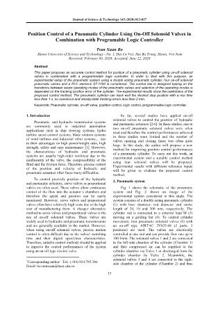
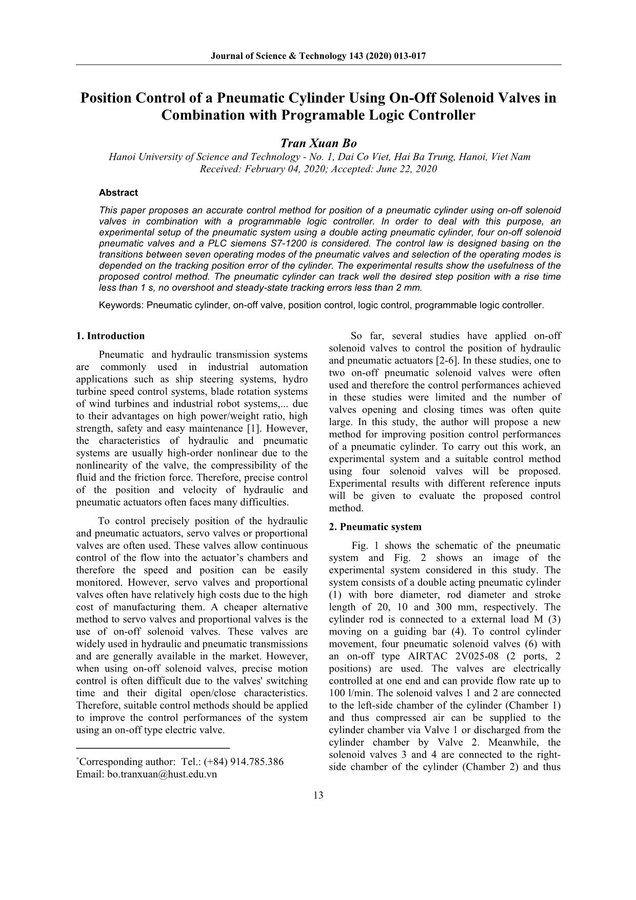
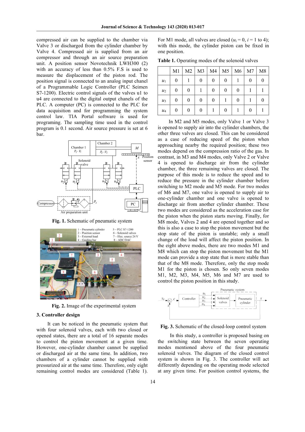
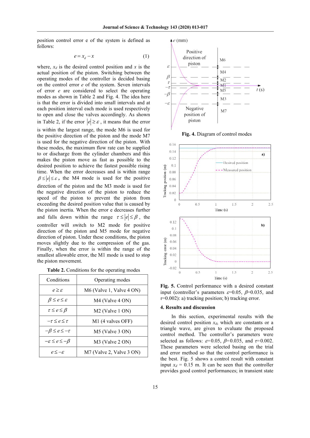
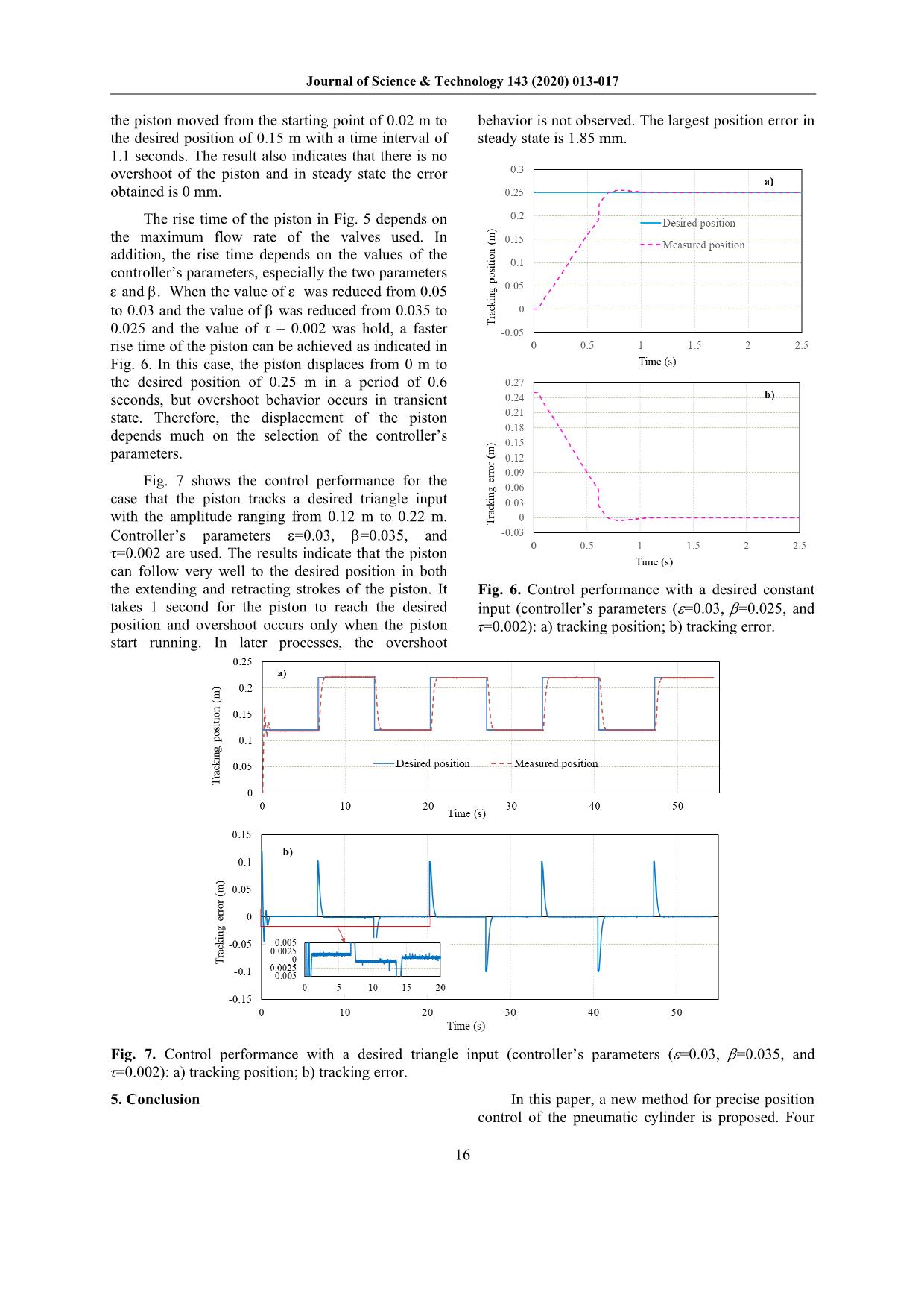
Control of a Pneumatic Cylinder Using On-Off Solenoid Valves in Combination with Programable Logic Controller Tran Xuan Bo Hanoi University of Science and Technology - No. 1, Dai Co Viet, Hai Ba Trung, Hanoi, Viet Nam Received: February 04, 2020; Accepted: June 22, 2020 Abstract This paper proposes an accurate control method for position of a pneumatic cylinder using on-off solenoid valves in combination with a programmable logic controller. In order to deal with this purpose, an experimental setup of the pneumatic system using a double acting pneumatic cylinder, four on-off solenoid pneumatic valves and a PLC siemens S7-1200 is considered. The control law is designed basing on the transitions between seven operating modes of the pneumatic valves and selection of the operating modes is depended on the tracking position error of the cylinder. The experimental results show the usefulness of the proposed control method. The pneumatic cylinder can track well the desired step position with a rise time less than 1 s, no overshoot and steady-state tracking errors less than 2 mm. Keywords: Pneumatic cylinder, on-off valve, position control, logic control, programmable logic controller. 1. Introduction Pneumatic* and hydraulic transmission systems are commonly used in industrial automation applications such as ship steering systems, hydro turbine speed control systems, blade rotation systems of wind turbines and industrial robot systems,... due to their advantages on high power/weight ratio, high strength, safety and easy maintenance [1]. However, the characteristics of hydraulic and pneumatic systems are usually high-order nonlinear due to the nonlinearity of the valve, the compressibility of the fluid and the friction force. Therefore, precise control of the position and velocity of hydraulic and pneumatic actuators often faces many difficulties. To control precisely position of the hydraulic and pneumatic actuators, servo valves or proportional valves are often used. These valves allow continuous control of the flow into the actuator’s chambers and therefore the speed and position can be easily monitored. However, servo valves and proportional valves often have relatively high costs due to the high cost of manufacturing them. A cheaper alternative method to servo valves and proportional valves is the use of on-off solenoid valves. These valves are widely used in hydraulic and pneumatic transmissions and are generally available in the market. However, when using on-off solenoid valves, precise motion control is often difficult due to the valves' switching time and their digital open/close characteristics. Therefore, suitable control methods should be applied to improve the control performances of the system using an on-off type electric valve. *Corresponding author: Tel.: (+84) 914.785.386 Email: bo.tranxuan@hust.edu.vn So far, several studies have applied on-off solenoid valves to control the position of hydraulic and pneumatic actuators [2-6]. In these studies, one to two on-off pneumatic solenoid valves were often used and therefore the control performances achieved in these studies were limited and the number of valves opening and closing times was often quite large. In this study, the author will propose a new method for improving position control performances of a pneumatic cylinder. To carry out this work, an experimental system and a suitable control method using four solenoid valves will be proposed. Experimental results with different reference inputs will be given to evaluate the proposed control method. 2. Pneumatic system Fig. 1 shows the schematic of the pneumatic system and Fig. 2 shows an image of the experimental system considered in this study. The system consists of a double acting pneumatic cylinder (1) with bore diameter, rod diameter and stroke length of 20, 10 and 300 mm, respectively. The cylinder rod is connected to a external load M (3) moving on a guiding bar (4). To control cylinder movement, four pneumatic solenoid valves (6) with an on-off type AIRTAC 2V025-08 (2 ports, 2 positions) are used. The valves are electrically controlled at one end and can provide flow rate up to 100 l/min. The solenoid valves 1 and 2 are connected to the left-side chamber of the cylinder (Chamber 1) and thus compressed air can be supplied to the cylinder chamber via Valve 1 or discharged from the cylinder chamber by Valve 2. Meanwhile, the solenoid valves 3 and 4 are connected to the right- side chamber of the cylinder (Chamber 2) and thus Journal of Science & Technology 143 (2020) 013-017 14 compressed air can be supplied to the chamber via Valve 3 or discharged from the cylinder chamber by Valve 4. Compressed air is supplied from an air compressor and through an air source preparation unit. A position sensor Novotechnik LWH300 (2) with an accuracy of less than 0.5% F.S is used to measure the displacement of the piston rod. The position signal is connected to an analog input chanel of a Programmable Logic Controller (PLC Seimen S7-1200). Electric control signals of the valves u1 to u4 are connected to the digital output chanels of the PLC. A computer (PC) is connected to the PLC for data acquisition and for programming the system control law. TIA Portal software is used for programing. The sampling time used in the control program is 0.1 second. Air source pressure is set at 6 bar. M PLC x Compressor Chamber 1 Chamber 2 Air preparation unit Position sensor PC u2 u1 u3 u4 p , 1 V1 p ,2 V2 p s Solenoid valve Fig. 1. Schematic of pneumatic system Fig. 2. Image of the experimental system 3. Controller design It can be noticed in the pneumatic system that with four solenoid valves, each with two closed or opened states, there are a total of 16 separate modes to control the piston movement at a given time. However, one-cylinder chamber cannot be supplied or discharged air at the same time. In addition, two chambers of a cylinder cannot be supplied with pressurized air at the same time. Therefore, only eight remaining control modes are considered (Table 1). For M1 mode, all valves are closed (ui = 0, i = 1 to 4); with this mode, the cylinder piston can be fixed in one position. Table 1. Operating modes of the solenoid valves M1 M2 M3 M4 M5 M6 M7 M8 u1 0 1 0 0 0 1 0 0 u2 0 0 1 0 0 0 1 1 u3 0 0 0 0 1 0 1 0 u4 0 0 0 1 0 1 0 1 In M2 and M5 modes, only Valve 1 or Valve 3 is opened to supply air into the cylinder chambers, the other three valves are closed. This can be considered as a case of reducing speed of the piston when approaching nearby the required position; these two modes depend on the compression ratio of the gas. In contrast, in M3 and M4 modes, only Valve 2 or Valve 4 is opened to discharge air from the cylinder chamber, the three remaining valves are closed. The purpose of this mode is to reduce the speed and to reduce the pressure in the cylinder chamber before switching to M2 mode and M5 mode. For two modes of M6 and M7, one valve is opened to supply air to one-cylinder chamber and one valve is opened to discharge air from another cylinder chamber. These two modes are considered as the acceleration case for the piston when the piston starts moving. Finally, for M8 mode, Valves 2 and 4 are opened together and so this is also a case to stop the piston movement but the stop state of the piston is unstable; only a small change of the load will affect the piston position. In the eight above modes, there are two modes M1 and M8 which can stop the piston movement but the M1 mode can provide a stop state that is more stable than that of the M8 mode. Therefore, only the stop mode M1 for the piston is chosen. So only seven modes M1, M2, M3, M4, M5, M6 and M7 are used to control the piston position in this study. Fig. 3. Schematic of the closed-loop control system In this study, a controller is proposed basing on the switching state between the seven operating modes mentioned above of the four pneumatic solenoid valves. The diagram of the closed control system is shown in Fig. 3. The controller will act differently depending on the operating mode selected at any given time. For position control systems, the Journal of Science & Technology 143 (2020) 013-017 15 position control error e of the system is defined as follows: de x x (1) where, xd is the desired control position and x is the actual position of the piston. Switching between the operating modes of the controller is decided basing on the control error e of the system. Seven intervals of error e are considered to select the operating modes as shown in Table 2 and Fig. 4. The idea here is that the error is divided into small intervals and at each position interval each mode is used respectively to open and close the valves accordingly. As shown in Table 2, if the error e , it means that the error is within the largest range, the mode M6 is used for the positive direction of the piston and the mode M7 is used for the negative direction of the piston. With these modes, the maximum flow rate can be supplied to or discharge from the cylinder chambers and this makes the piston move as fast as possible to the desired position to achieve the fastest possible rising time. When the error decreases and is within range e , the M4 mode is used for the positive direction of the piston and the M3 mode is used for the negative direction of the piston to reduce the speed of the piston to prevent the piston from exceeding the desired position value that is caused by the piston inertia. When the error e decreases further and falls down within the range e , the controller will switch to M2 mode for positive direction of the piston and M5 mode for negative direction of piston. Under these conditions, the piston moves slightly due to the compression of the gas. Finally, when the error is within the range of the smallest allowable error, the M1 mode is used to stop the piston movement. Table 2. Conditions for the operating modes Conditions Operating modes e M6 (Valve 1, Valve 4 ON) e M4 (Valve 4 ON) e M2 (Valve 1 ON) e M1 (4 valves OFF) e M5 (Valve 3 ON) e M3 (Valve 2 ON) e M7 (Valve 2, Valve 3 ON) Fig. 4. Diagram of control modes Fig. 5. Control performance with a desired constant input (controller’s parameters =0.05, =0.035, and τ=0.002): a) tracking position; b) tracking error. 4. Results and discussion In this section, experimental results with the desired control position xd, which are constants or a triangle wave, are given to evaluate the proposed control method. The controller’s parameters were selected as follows: =0.05, =0.035, and τ=0.002. These parameters were selected basing on the trial and error method so that the control performance is the best. Fig. 5 shows a control result with constant input xd = 0.15 m. It can be seen that the controller provides good control performances; in transient state Journal of Science & Technology 143 (2020) 013-017 16 the piston moved from the starting point of 0.02 m to the desired position of 0.15 m with a time interval of 1.1 seconds. The result also indicates that there is no overshoot of the piston and in steady state the error obtained is 0 mm. The rise time of the piston in Fig. 5 depends on the maximum flow rate of the valves used. In addition, the rise time depends on the values of the controller’s parameters, especially the two parameters and . When the value of was reduced from 0.05 to 0.03 and the value of was reduced from 0.035 to 0.025 and the value of τ = 0.002 was hold, a faster rise time of the piston can be achieved as indicated in Fig. 6. In this case, the piston displaces from 0 m to the desired position of 0.25 m in a period of 0.6 seconds, but overshoot behavior occurs in transient state. Therefore, the displacement of the piston depends much on the selection of the controller’s parameters. Fig. 7 shows the control performance for the case that the piston tracks a desired triangle input with the amplitude ranging from 0.12 m to 0.22 m. Controller’s parameters =0.03, =0.035, and τ=0.002 are used. The results indicate that the piston can follow very well to the desired position in both the extending and retracting strokes of the piston. It takes 1 second for the piston to reach the desired position and overshoot occurs only when the piston start running. In later processes, the overshoot behavior is not observed. The largest position error in steady state is 1.85 mm. Fig. 6. Control performance with a desired constant input (controller’s parameters (=0.03, =0.025, and τ=0.002): a) tracking position; b) tracking error. Fig. 7. Control performance with a desired triangle input (controller’s parameters (=0.03, =0.035, and τ=0.002): a) tracking position; b) tracking error. 5. Conclusion In this paper, a new method for precise position control of the pneumatic cylinder is proposed. Four Journal of Science & Technology 143 (2020) 013-017 17 two-position two-port pneumatic on-off solenoid valves were used and a logic control algorithm based on the seven operating modes of the valves was considered. Each cylinder chamber was connected with two valves to increase the control ability of the piston position Experimental studies was conducted and the experimental results indicated that the control method yielded high-precision control performances with fast rise times under 1 second and steady-state errors of less than 2 mm. References [1] J. Watton, Fundamentals of fluid power control, Cambridge University Press, 2009. [2] R. B. van Varseveld, G. M. Bone, Accurate position control of a pneumatic actuator using on/off solenoid valves, IEEE/ASME Transactions on Mechatronics, 2 (1997) 195-204. [3] K. Ahn, S. Yokota, Intelligent switching control of pneumatic actuator using on/off solenoid valves, Mechatronics 15 (2005) 683–702. [4] X. Shen, J. Zhang, E. J. Barth, M. Goldfarb, Nonlinear model-based control of pulse width modulated pneumatic servo systems, Journal of Dynamic Systems, Measurement, and Control, 128 (2006) 663- 669. [5] T. Nguyen, J. Leavitt, F. Jabbari, and J. E. Bobrow, Accurate Sliding-Mode Control of Pneumatic Systems Using Low-Cost Solenoid Valves, IEEE/ASME Transactions on Mechatronics, 12 (2007) 216-219. [6] S. Hodgson, M. Q. Le, M. Tavakoli, M. T. Pham, Improved tracking and switching performance of an electro-pneumatic positioning system, Mechatronics 22 (2012) 1–12.
File đính kèm:
 position_control_of_a_pneumatic_cylinder_using_on_off_soleno.pdf

