Nghiên cứu thực nghiệm về chẩn đoán lỗi cảm biến cho việc giám sát sức khỏe kết cấu bằng kỹ thuật giao diện áp điện
Sự hoạt động ổn định của các cảm biến là rất quan trọng đối với hệ thống theo dõi sức khỏe công trình. Các lỗi cảm
biến sẽ gây ra những thay đổi đáng kể trong những tín hiệu đo được, dẫn đến những chuẩn đoán sai lệch về tình trạng
sức khỏe của công trình. Bài báo này trình bày một nghiên cứu thực nghiệm về chẩn đoán lỗi cảm biến cho việc theo
dõi sức khỏe kết cấu bằng kỹ thuật giao diện áp điện. Đầu tiên, phương pháp giám sát trở kháng bằng kỹ thuật giao diện
áp điện thông minh được giới thiệu. Tiếp theo, các ảnh hưởng của lỗi cảm biến đối với trở kháng của kết cấu được
nghiên cứu thông qua các thí nghiệm đo trở kháng, được tiến hành trên một mối nối bu-lông bằng thép. Cuối cùng, đặc
trưng trở kháng được trích lọc và sử dụng để chẩn đoán các lỗi cảm biến và phân biệt chúng với các hư hỏng của công
trình. Kết quả thí nghiệm cho thấy các lỗi cảm biến có thể gây ra những thay đổi đáng kể đến tín hiệu trở kháng và các
lỗi cảm biến này có thể được phân biệt một cách hiệu quả với những hư hỏng công trình bằng cách sử dụng đặc trưng
trở kháng.

Trang 1
Trang 2
Trang 3
Trang 4
Trang 5
Trang 6
Trang 7
Trang 8
Tóm tắt nội dung tài liệu: Nghiên cứu thực nghiệm về chẩn đoán lỗi cảm biến cho việc giám sát sức khỏe kết cấu bằng kỹ thuật giao diện áp điện

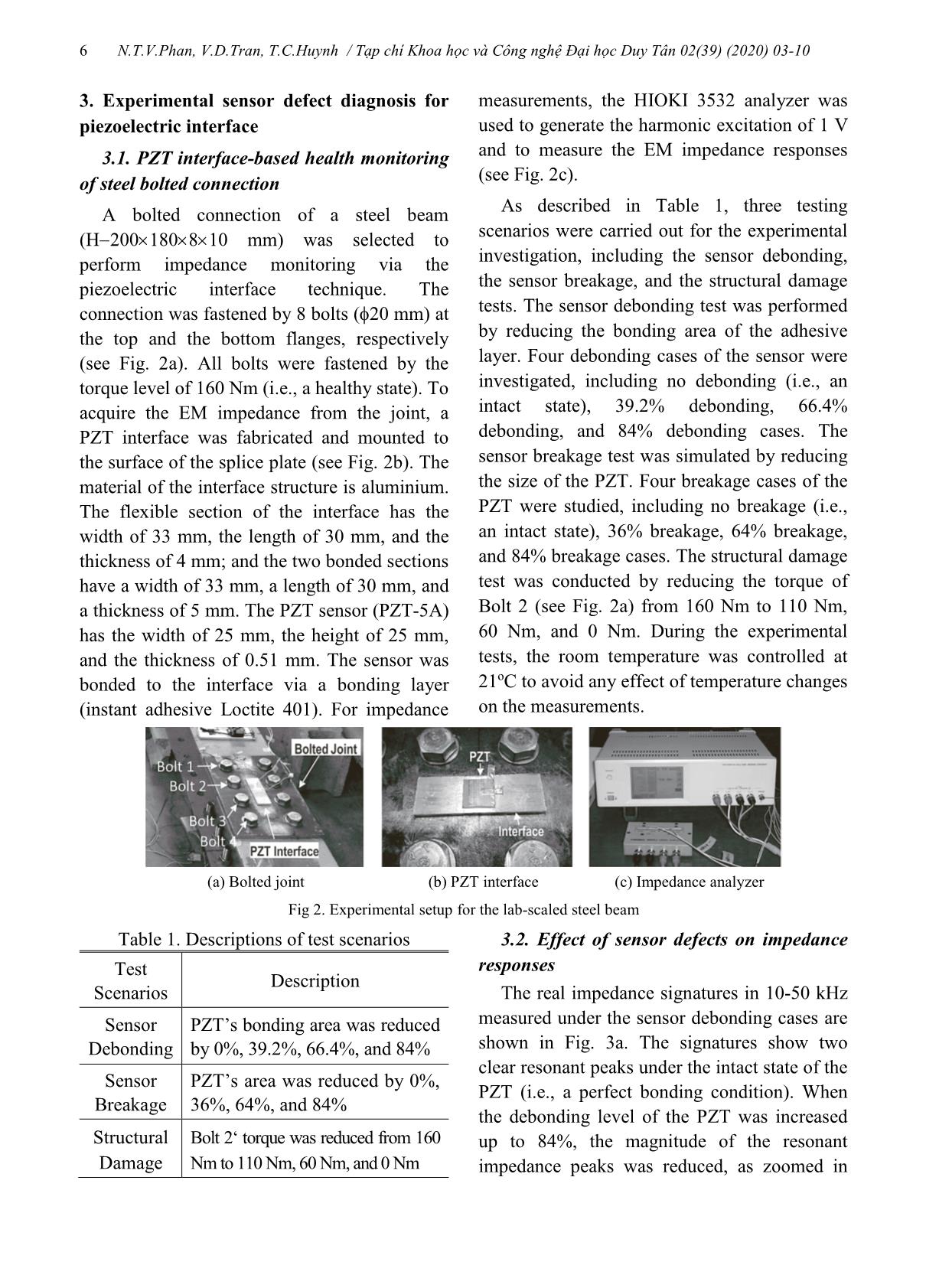
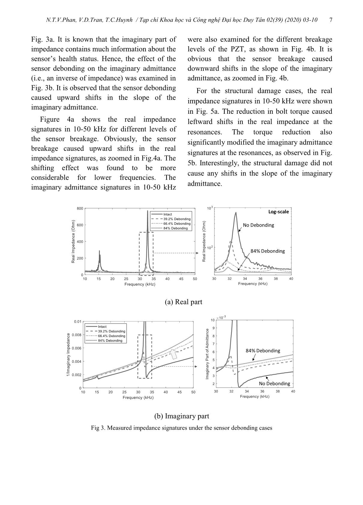
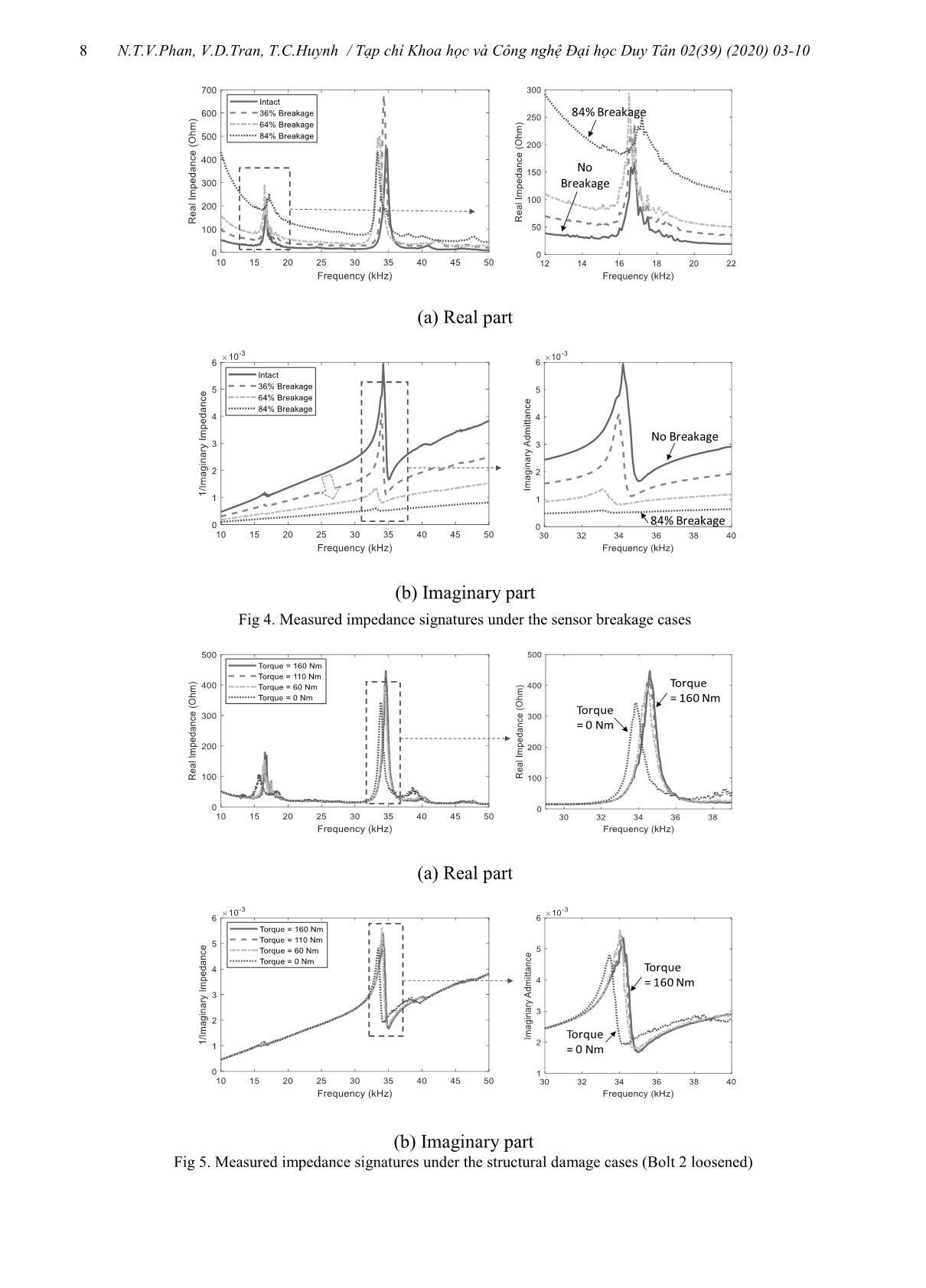
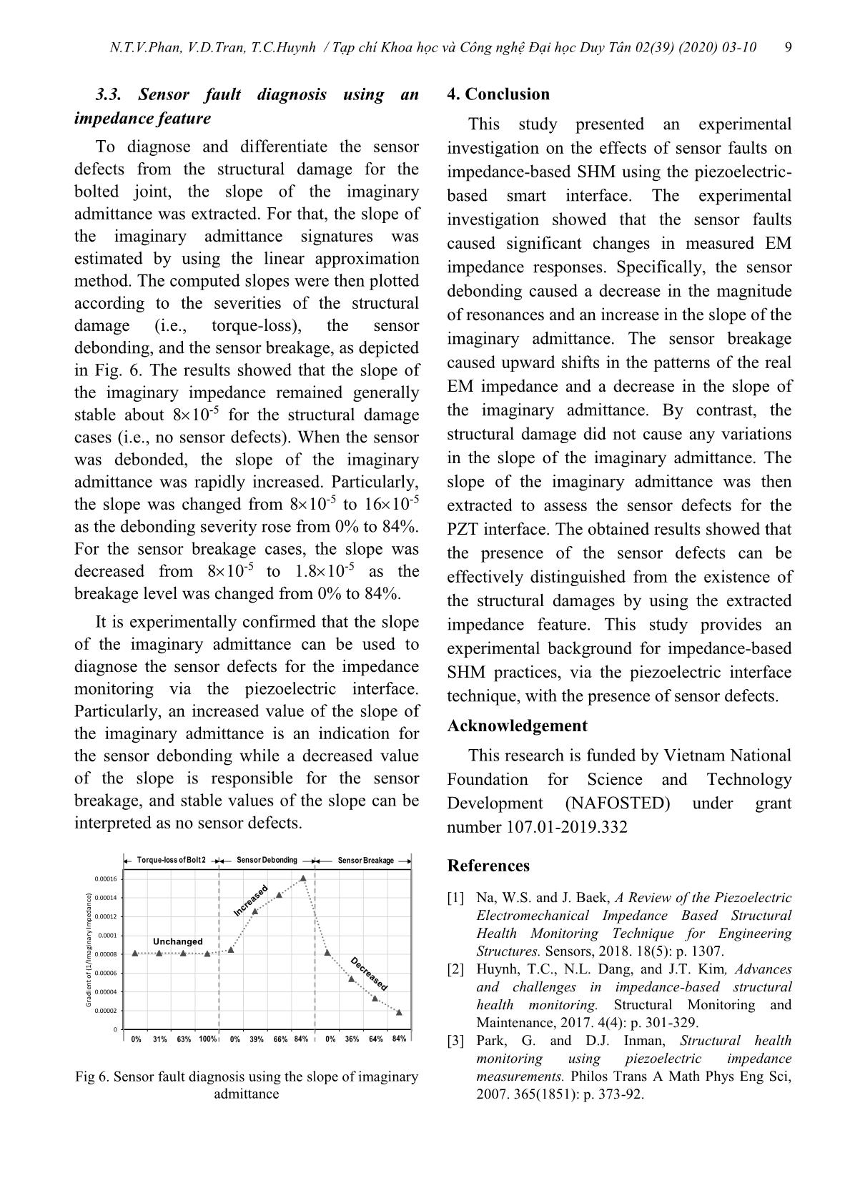
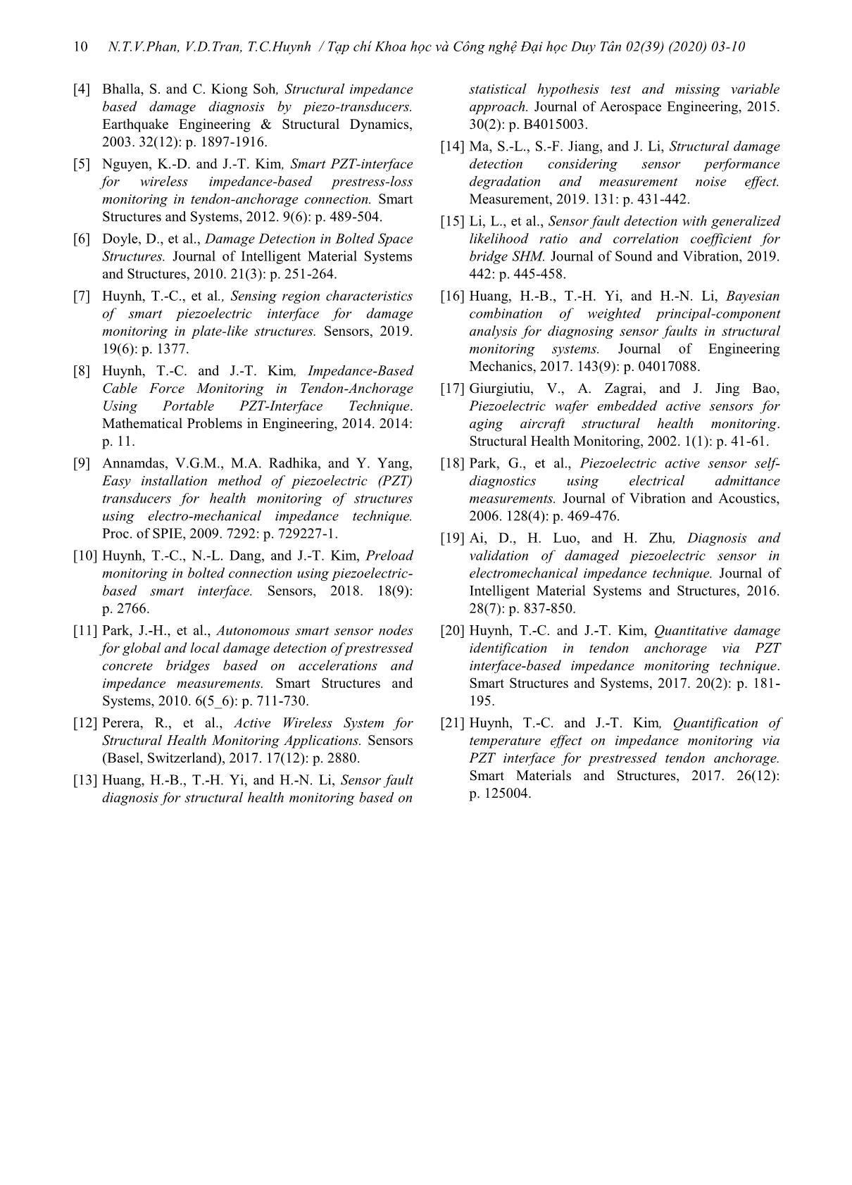
the coupled interface-host structure ( )Z , as described below: (1) where ˆ (1 )E Exx xxY i Y is the complex Young’s modulus of the PZT patch at a zero electric field; ˆ (1 )T Txx xxi is the complex dielectric constant at zero stress; d3x is the piezoelectric coupling constant in the x-direction at zero stress; and wa, la, and ta are the width, length, and thickness of the PZT patch, respectively. The parameters and are structural damping loss factor and dielectric loss factor of piezoelectric material, respectively. The SM impedance of the coupled interface-host structure system ( )Z can be computed from the following equation [21]: (2) Equation (2) shows that the SM impedance of the coupled interface-host structure system is characterized by the masses, damping, and stiffness of both the interface (ki, ci, mi) and the host structure (ks, cs, ms). Thus, the change in these parameters caused by structural damages can be represented by the change in the EM impedance obtained from the PZT sensor. By quantifying the variations of EM impedance signals, the structural damage occurred in the host structure can be detected. To successfully implement a damage detection job, it is important to confirm the operation of the PZT sensor. In a realistic situation, the sensor and its bonding layer can be degraded under the effects of overloading conditions, material deteriorations, and environmental changes. The sensor breakage/ quality degradation will cause changes in piezoelectric properties. Also, the bonding layer’s defects will affect the force transmission from the PZT to the interface structure. As a result, observable changes in the measured EM impedance could be inaccurately interpreted as the occurrence of structural damages. 1 2 33 31 11 1 ˆˆ( ) ( ) ( ) 1 T Ea a a a w lV Z i d Y I t Z Z 22 2 2 ( ) ( ) ( ) ( ) ( ) i i i s i s i s i i s i s i s m i c k m i c c k k i c k Z i m i c c k k N.T.V.Phan, V.D.Tran, T.C.Huynh / Tạp chí Khoa học và Công nghệ Đại học Duy Tân 02(39) (2020) 03-10 6 3. Experimental sensor defect diagnosis for piezoelectric interface 3.1. PZT interface-based health monitoring of steel bolted connection A bolted connection of a steel beam (H 200 180 8 10 mm) was selected to perform impedance monitoring via the piezoelectric interface technique. The connection was fastened by 8 bolts (20 mm) at the top and the bottom flanges, respectively (see Fig. 2a). All bolts were fastened by the torque level of 160 Nm (i.e., a healthy state). To acquire the EM impedance from the joint, a PZT interface was fabricated and mounted to the surface of the splice plate (see Fig. 2b). The material of the interface structure is aluminium. The flexible section of the interface has the width of 33 mm, the length of 30 mm, and the thickness of 4 mm; and the two bonded sections have a width of 33 mm, a length of 30 mm, and a thickness of 5 mm. The PZT sensor (PZT-5A) has the width of 25 mm, the height of 25 mm, and the thickness of 0.51 mm. The sensor was bonded to the interface via a bonding layer (instant adhesive Loctite 401). For impedance measurements, the HIOKI 3532 analyzer was used to generate the harmonic excitation of 1 V and to measure the EM impedance responses (see Fig. 2c). As described in Table 1, three testing scenarios were carried out for the experimental investigation, including the sensor debonding, the sensor breakage, and the structural damage tests. The sensor debonding test was performed by reducing the bonding area of the adhesive layer. Four debonding cases of the sensor were investigated, including no debonding (i.e., an intact state), 39.2% debonding, 66.4% debonding, and 84% debonding cases. The sensor breakage test was simulated by reducing the size of the PZT. Four breakage cases of the PZT were studied, including no breakage (i.e., an intact state), 36% breakage, 64% breakage, and 84% breakage cases. The structural damage test was conducted by reducing the torque of Bolt 2 (see Fig. 2a) from 160 Nm to 110 Nm, 60 Nm, and 0 Nm. During the experimental tests, the room temperature was controlled at 21oC to avoid any effect of temperature changes on the measurements. (a) Bolted joint (b) PZT interface (c) Impedance analyzer Fig 2. Experimental setup for the lab-scaled steel beam Table 1. Descriptions of test scenarios Test Scenarios Description Sensor Debonding PZT’s bonding area was reduced by 0%, 39.2%, 66.4%, and 84% Sensor Breakage PZT’s area was reduced by 0%, 36%, 64%, and 84% Structural Damage Bolt 2‘ torque was reduced from 160 Nm to 110 Nm, 60 Nm, and 0 Nm 3.2. Effect of sensor defects on impedance responses The real impedance signatures in 10-50 kHz measured under the sensor debonding cases are shown in Fig. 3a. The signatures show two clear resonant peaks under the intact state of the PZT (i.e., a perfect bonding condition). When the debonding level of the PZT was increased up to 84%, the magnitude of the resonant impedance peaks was reduced, as zoomed in N.T.V.Phan, V.D.Tran, T.C.Huynh / Tạp chí Khoa học và Công nghệ Đại học Duy Tân 02(39) (2020) 03-10 7 Fig. 3a. It is known that the imaginary part of impedance contains much information about the sensor’s health status. Hence, the effect of the sensor debonding on the imaginary admittance (i.e., an inverse of impedance) was examined in Fig. 3b. It is observed that the sensor debonding caused upward shifts in the slope of the imaginary admittance. Figure 4a shows the real impedance signatures in 10-50 kHz for different levels of the sensor breakage. Obviously, the sensor breakage caused upward shifts in the real impedance signatures, as zoomed in Fig.4a. The shifting effect was found to be more considerable for lower frequencies. The imaginary admittance signatures in 10-50 kHz were also examined for the different breakage levels of the PZT, as shown in Fig. 4b. It is obvious that the sensor breakage caused downward shifts in the slope of the imaginary admittance, as zoomed in Fig. 4b. For the structural damage cases, the real impedance signatures in 10-50 kHz were shown in Fig. 5a. The reduction in bolt torque caused leftward shifts in the real impedance at the resonances. The torque reduction also significantly modified the imaginary admittance signatures at the resonances, as observed in Fig. 5b. Interestingly, the structural damage did not cause any shifts in the slope of the imaginary admittance. (b) Imaginary part Fig 3. Measured impedance signatures under the sensor debonding cases No Debonding 84% Debonding Log-scale (a) Real part 84% Debonding No Debonding N.T.V.Phan, V.D.Tran, T.C.Huynh / Tạp chí Khoa học và Công nghệ Đại học Duy Tân 02(39) (2020) 03-10 8 (b) Imaginary part Fig 5. Measured impedance signatures under the structural damage cases (Bolt 2 loosened) 84% Breakage No Breakage (a) Real part 84% Breakage No Breakage (b) Imaginary part Fig 4. Measured impedance signatures under the sensor breakage cases Torque = 0 Nm Torque = 160 Nm (a) Real part Torque = 0 Nm Torque = 160 Nm N.T.V.Phan, V.D.Tran, T.C.Huynh / Tạp chí Khoa học và Công nghệ Đại học Duy Tân 02(39) (2020) 03-10 9 3.3. Sensor fault diagnosis using an impedance feature To diagnose and differentiate the sensor defects from the structural damage for the bolted joint, the slope of the imaginary admittance was extracted. For that, the slope of the imaginary admittance signatures was estimated by using the linear approximation method. The computed slopes were then plotted according to the severities of the structural damage (i.e., torque-loss), the sensor debonding, and the sensor breakage, as depicted in Fig. 6. The results showed that the slope of the imaginary impedance remained generally stable about 8 10-5 for the structural damage cases (i.e., no sensor defects). When the sensor was debonded, the slope of the imaginary admittance was rapidly increased. Particularly, the slope was changed from 8 10-5 to 16 10-5 as the debonding severity rose from 0% to 84%. For the sensor breakage cases, the slope was decreased from 8 10-5 to 1.8 10-5 as the breakage level was changed from 0% to 84%. It is experimentally confirmed that the slope of the imaginary admittance can be used to diagnose the sensor defects for the impedance monitoring via the piezoelectric interface. Particularly, an increased value of the slope of the imaginary admittance is an indication for the sensor debonding while a decreased value of the slope is responsible for the sensor breakage, and stable values of the slope can be interpreted as no sensor defects. 0 0.00002 0.00004 0.00006 0.00008 0.0001 0.00012 0.00014 0.00016 G ra d ie n t o f (1 /I m a gi n a ry Im p ed a n ce ) Unchanged Sensor BreakageTorque-loss of Bolt 2 Sensor Debonding 0% 31% 63% 100% 0% 39% 66% 84% 0% 36% 64% 84% Fig 6. Sensor fault diagnosis using the slope of imaginary admittance 4. Conclusion This study presented an experimental investigation on the effects of sensor faults on impedance-based SHM using the piezoelectric- based smart interface. The experimental investigation showed that the sensor faults caused significant changes in measured EM impedance responses. Specifically, the sensor debonding caused a decrease in the magnitude of resonances and an increase in the slope of the imaginary admittance. The sensor breakage caused upward shifts in the patterns of the real EM impedance and a decrease in the slope of the imaginary admittance. By contrast, the structural damage did not cause any variations in the slope of the imaginary admittance. The slope of the imaginary admittance was then extracted to assess the sensor defects for the PZT interface. The obtained results showed that the presence of the sensor defects can be effectively distinguished from the existence of the structural damages by using the extracted impedance feature. This study provides an experimental background for impedance-based SHM practices, via the piezoelectric interface technique, with the presence of sensor defects. Acknowledgement This research is funded by Vietnam National Foundation for Science and Technology Development (NAFOSTED) under grant number 107.01-2019.332 References [1] Na, W.S. and J. Baek, A Review of the Piezoelectric Electromechanical Impedance Based Structural Health Monitoring Technique for Engineering Structures. Sensors, 2018. 18(5): p. 1307. [2] Huynh, T.C., N.L. Dang, and J.T. Kim, Advances and challenges in impedance-based structural health monitoring. Structural Monitoring and Maintenance, 2017. 4(4): p. 301-329. [3] Park, G. and D.J. Inman, Structural health monitoring using piezoelectric impedance measurements. Philos Trans A Math Phys Eng Sci, 2007. 365(1851): p. 373-92. N.T.V.Phan, V.D.Tran, T.C.Huynh / Tạp chí Khoa học và Công nghệ Đại học Duy Tân 02(39) (2020) 03-10 10 [4] Bhalla, S. and C. Kiong Soh, Structural impedance based damage diagnosis by piezo-transducers. Earthquake Engineering & Structural Dynamics, 2003. 32(12): p. 1897-1916. [5] Nguyen, K.-D. and J.-T. Kim, Smart PZT-interface for wireless impedance-based prestress-loss monitoring in tendon-anchorage connection. Smart Structures and Systems, 2012. 9(6): p. 489-504. [6] Doyle, D., et al., Damage Detection in Bolted Space Structures. Journal of Intelligent Material Systems and Structures, 2010. 21(3): p. 251-264. [7] Huynh, T.-C., et al., Sensing region characteristics of smart piezoelectric interface for damage monitoring in plate-like structures. Sensors, 2019. 19(6): p. 1377. [8] Huynh, T.-C. and J.-T. Kim, Impedance-Based Cable Force Monitoring in Tendon-Anchorage Using Portable PZT-Interface Technique. Mathematical Problems in Engineering, 2014. 2014: p. 11. [9] Annamdas, V.G.M., M.A. Radhika, and Y. Yang, Easy installation method of piezoelectric (PZT) transducers for health monitoring of structures using electro-mechanical impedance technique. Proc. of SPIE, 2009. 7292: p. 729227-1. [10] Huynh, T.-C., N.-L. Dang, and J.-T. Kim, Preload monitoring in bolted connection using piezoelectric- based smart interface. Sensors, 2018. 18(9): p. 2766. [11] Park, J.-H., et al., Autonomous smart sensor nodes for global and local damage detection of prestressed concrete bridges based on accelerations and impedance measurements. Smart Structures and Systems, 2010. 6(5_6): p. 711-730. [12] Perera, R., et al., Active Wireless System for Structural Health Monitoring Applications. Sensors (Basel, Switzerland), 2017. 17(12): p. 2880. [13] Huang, H.-B., T.-H. Yi, and H.-N. Li, Sensor fault diagnosis for structural health monitoring based on statistical hypothesis test and missing variable approach. Journal of Aerospace Engineering, 2015. 30(2): p. B4015003. [14] Ma, S.-L., S.-F. Jiang, and J. Li, Structural damage detection considering sensor performance degradation and measurement noise effect. Measurement, 2019. 131: p. 431-442. [15] Li, L., et al., Sensor fault detection with generalized likelihood ratio and correlation coefficient for bridge SHM. Journal of Sound and Vibration, 2019. 442: p. 445-458. [16] Huang, H.-B., T.-H. Yi, and H.-N. Li, Bayesian combination of weighted principal-component analysis for diagnosing sensor faults in structural monitoring systems. Journal of Engineering Mechanics, 2017. 143(9): p. 04017088. [17] Giurgiutiu, V., A. Zagrai, and J. Jing Bao, Piezoelectric wafer embedded active sensors for aging aircraft structural health monitoring. Structural Health Monitoring, 2002. 1(1): p. 41-61. [18] Park, G., et al., Piezoelectric active sensor self- diagnostics using electrical admittance measurements. Journal of Vibration and Acoustics, 2006. 128(4): p. 469-476. [19] Ai, D., H. Luo, and H. Zhu, Diagnosis and validation of damaged piezoelectric sensor in electromechanical impedance technique. Journal of Intelligent Material Systems and Structures, 2016. 28(7): p. 837-850. [20] Huynh, T.-C. and J.-T. Kim, Quantitative damage identification in tendon anchorage via PZT interface-based impedance monitoring technique. Smart Structures and Systems, 2017. 20(2): p. 181- 195. [21] Huynh, T.-C. and J.-T. Kim, Quantification of temperature effect on impedance monitoring via PZT interface for prestressed tendon anchorage. Smart Materials and Structures, 2017. 26(12): p. 125004.
File đính kèm:
 nghien_cuu_thuc_nghiem_ve_chan_doan_loi_cam_bien_cho_viec_gi.pdf

