Model predictive control for industrial applications of three - Phase inverters
This paper proposes a Model Predictive Control (MPC) method used for DC-AC
converter applications to connect the electrical systems in industry. DC-AC inverters used to
convert DC power into AC power for supplying to an AC load. Parameters are controlled in
output voltage value or current value, corresponding to voltage source inverter (VSI) inverter
and current source inverter (VSC) [1]. DC-AC converter phase three is the main part of the
three-phase inverter. Today, controlling for DC-AC inverter has many methods applied [2]-
[3]. However, the FCS-MPC method has many advantages: Impact fast, easy to apply, high
conversion efficiency, etc. The design procedure of FCS-MPC is based on first, a discretetime model of the system that is used to predict the behavior of the controlled variables for all
the possible switching states of the converter and second, a cost function should be defined
according to the control requirements of the system [1]-[2]. The switching state that
minimizes the cost function will be selected to be applied to the converter at the next sampling
time [4]. This study presents in detail description of a cost function-based predictive control
strategy called Finite Control Set Model Predictive Control (FCS-MPC) and its applications
to the control of power electronics converters DC-AC.
Trang 1
Trang 2

Trang 3
Trang 4
Trang 5
Trang 6
Trang 7
Trang 8
Tóm tắt nội dung tài liệu: Model predictive control for industrial applications of three - Phase inverters
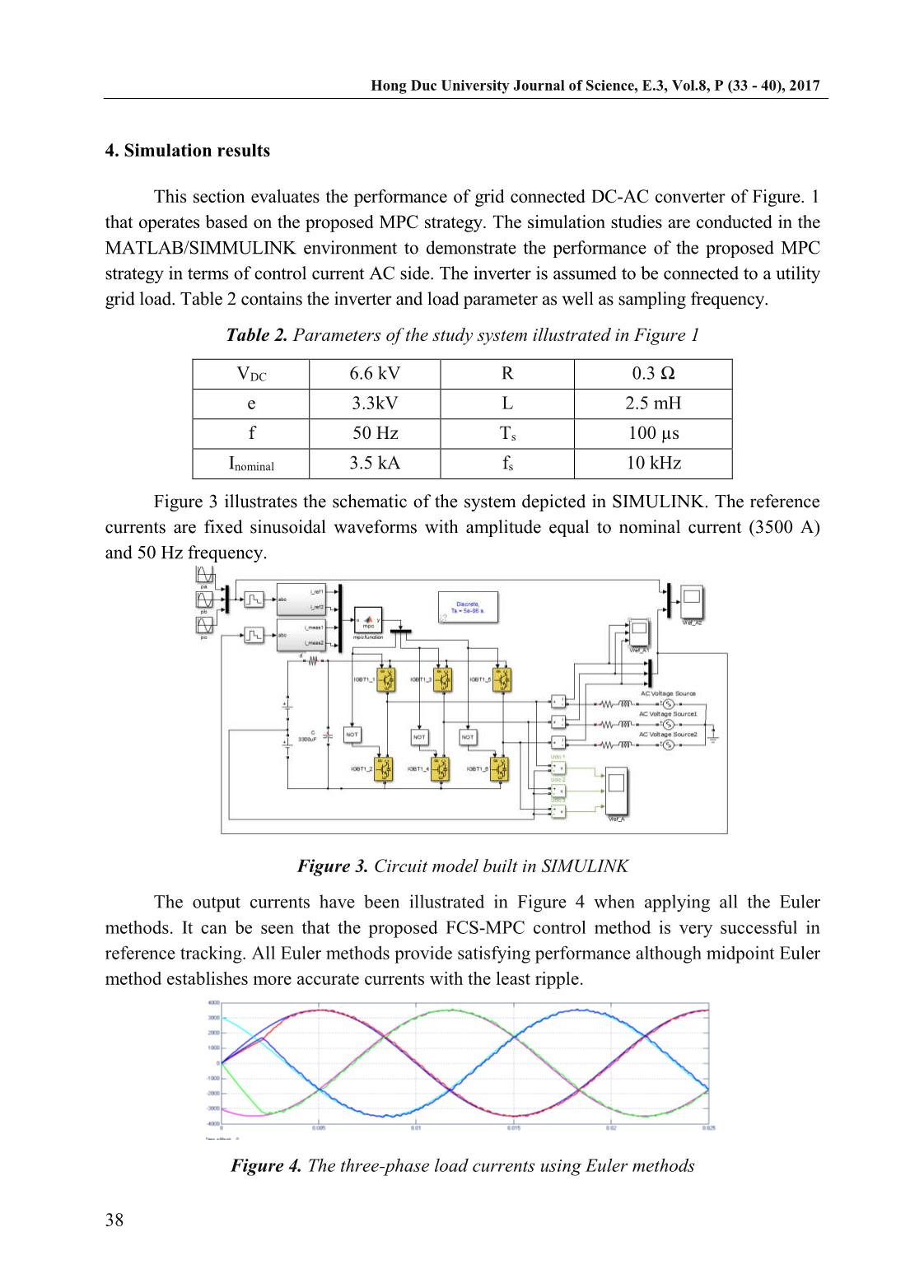
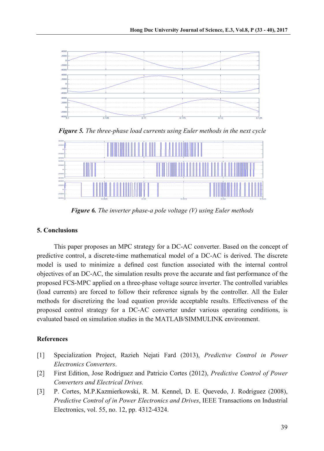
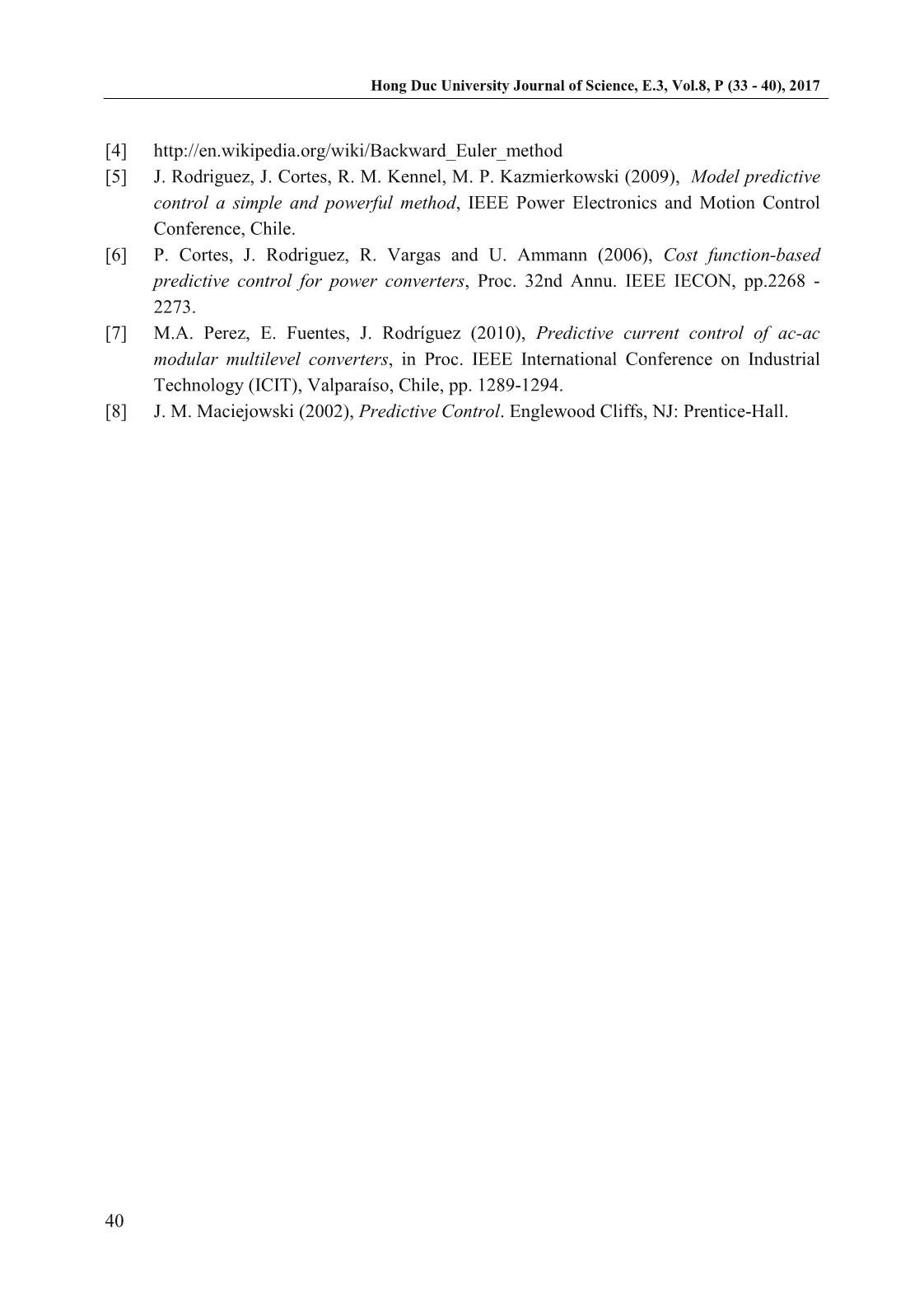
r DC-AC converter applications to connect the electrical systems in industry. DC-AC inverters used to convert DC power into AC power for supplying to an AC load. Parameters are controlled in output voltage value or current value, corresponding to voltage source inverter (VSI) inverter and current source inverter (VSC) [1]. DC-AC converter phase three is the main part of the three-phase inverter. Today, controlling for DC-AC inverter has many methods applied [2]- [3]. However, the FCS-MPC method has many advantages: Impact fast, easy to apply, high conversion efficiency, etc. The design procedure of FCS-MPC is based on first, a discrete- time model of the system that is used to predict the behavior of the controlled variables for all the possible switching states of the converter and second, a cost function should be defined according to the control requirements of the system [1]-[2]. The switching state that minimizes the cost function will be selected to be applied to the converter at the next sampling time [4]. This study presents in detail description of a cost function-based predictive control strategy called Finite Control Set Model Predictive Control (FCS-MPC) and its applications to the control of power electronics converters DC-AC. Keywords: DC-AC converter, Model Predictive Control (MPC), Voltage source inverter. 1. Introduction The power electronics converter typically includes the voltage converter DC-DC, DC-AC [3]. DC-AC converter is the device changing direct current into alternating current with the frequency which can be changed and work with independent load [3]. DC power is voltage rectifiers, battery and DC power sources independent. Today, Independent inverter has been widely used in fields such as electricity supply from independent sources such as batteries, AC drive systems, communications, power transmission, metallurgy, energy savings, used in daily life when grid power has been cut... [2]. In fact, three-phase inverters are commonly used Tran Hung Cuong Faculty of Engineering and Technology, Hong Duc University Email: Tranhungcuong@hdu.edu.vn ( ) Le Phuong Hao Faculty of Engineering and Technology, Hong Duc University Email: Lephuonghao@hdu.edu.vn ( ) Hong Duc University Journal of Science, E.3, Vol.8, P (33 - 40), 2017 34 because it has large capacity and satisfy industrial applications. Currently, there have been many studies to design the controller for DC-AC converter to create the alternating high quality currents. However, applying the classic controller will be difficult for DC-AC converter high capacity such as the switching frequency of large valves, system power loss, in the alternating currents instability leading to affect the quality of converter [1]. In this paper, Finite Control Set Model Predictive Control will be applied to a simple three-phase voltage source inverter (VSI) which is connected to a typical R-L-e load. The designed controller capabilities are verified by simulating the system in MATLAB/SIMULINK. Model Predictive Control or MPC was first introduced in 1960s. It has more complex calculations compared to classical linear controllers, while it provides faster controller with higher accuracy and stability. From 1980s, the idea of MPC in power electronics applications was introduced despite the lack of fast processors at that time, limited its applications only to low switching frequencies [1]-[2]. Due to invention of fast and powerful processors such as DSP and FPGA, the power electronics industry could take advantages of MPC strategy in practice. Many papers have studied a finite MPC method to control the power converter [4]. Based on MPC, three alternatives have been introduced in order to reduce its high amount of calculations; Generalized Predictive Control (GPC), Explicit MPC and Finite Control Set MPC (FCS-MPC). The focus of this study will be on FCS-MPC, because FCS-MPC is a powerful control technique that has several advantages such as high accuracy, flexibility and stability, easy implementation, simple and understandable concepts, but the most important and exclusive feature of this control strategy is the inclusion of nonlinearities and system constraints in the cost function. As a result, all the control requirements can be considered by one controller at the same time [4 - 8]. The details are described in the following parts. In Section 2, the system structure and operating principles of the DC-AC are introduced. Section 3 presents the design of control system. In Section 4, simulations studies analyses are carried out in the Matlab/Simulink software. Conclusions are summarized in Section 5. 2. The DC-AC three phase voltage source converter 2.1. Structure DC-AC converter Three-phase/two-level voltage source inverter is a very well-known topology in power electronics. It has six power switch-diode combinations. The circuit diagram of the three- phase inverter connected to an RLe load has been illustrated in Figure1. Figure 1. Voltage source inverter power circuit Hong Duc University Journal of Science, E.3, Vol.8, P (33 - 40), 2017 35 IGBT has been selected to be power switches. The transient switching time will be neglected and only two possible states for each IGBT is going to be assumed that are completely ON or completely OFF. These switching states are not acceptable: Both of switches in each phase are ON at the same time (short circuiting the dc link). Both of switches in each phase are OFF at the same time (no power transfer) Consequently, eight (23) possible switching states can be found (Table 1). The load consists of three branches of a resistor (R), an inductor (L) and a voltage source (e) that have been connected together in star shape. This voltage source can be a representation of motor back emf. 2.2. Modeling of DC-AC converters As space vector analysis is a good method in order to simplify three phase equations to a single equation, the mathematical equation of the load will be: di v L Ri e dt (1) Where �, �and �are the representations of the inverter terminal voltage, phase currents and load back emf space vectors, respectively. They can be found by the following equations based on the space vector theorem. 2 2 3 a b ci i ai a i (2) 2 2 3 a b ce e ae a e (3) 2 2 3 aN bN cNv v av a v (4) 2 3 1 3 2 2 j a e j (5) Based on this approach and the inverter topology depicted in Figure 1, the relation between switching states and terminal voltage can be found (Table 1). Table 1. Switching states and voltage vectors State S1 S2 S3 S4 S5 S6 Inverter terminal voltage space vector v 0 0 1 0 1 0 1 0 0v 1 1 0 0 1 0 1 1 2 3 dcv V 2 0 1 1 0 0 1 2 1 1 3 3 dcv j V 3 0 1 0 1 1 0 3 1 1 3 3 dcv j V Hong Duc University Journal of Science, E.3, Vol.8, P (33 - 40), 2017 36 4 1 0 1 0 0 1 4 1 1 3 3 dcv j V 5 1 0 0 1 1 0 5 1 1 3 3 dcv j V 6 0 1 1 0 1 0 6 2 3 dcv V 7 1 0 1 0 1 0 7 0v 3. Proposed MPC strategy based on the mathematical model of the DC-AC converter 3.1. Introduction of Model Predictive Control The operating principle of MPC based on the cost function can contain different linear functions and depend on the characteristics of each system [8]. Where x(k) is the controlled variables. Based on the discrete model of system (load and converter), the current values of the controlled variables x(k) are used to predict their future values x(k+1) for all N possible switching states. All the predicted values of the controlled variables x(k+1) are compared with their reference values xref(k+1) in the cost function minimization block. Finally, the switching state (S) that minimizes the cost function will be selected as the next switching state and it will be applied to the converter. The procedure of switching state selection has been shown in Figure 3; tkis presenting the current state, tk+1and tk+2are the next time steps. The sampling time is Ts. Figure 2. The control lock diagram of MPC MPC model applied to the inverter power electronics began with discrete variables such as current, voltage, etc. The cost function must be determined according to the desired behavior of the system. At each sample time, the cost function will calculate all the switching status for the next sample cycle based on the present state. Then, the optimal state will be selected to apply for the conversion. In designing controller MPC for power electronics there are three phases: Perform discrete model of the system under control variables to be able to predict the future of the variable; Identify all the switching states for conversions and their Hong Duc University Journal of Science, E.3, Vol.8, P (33 - 40), 2017 37 relationship with other variables; Determine the cost function to calculate the optimum value representing the desired behavior of the system. 3.2. MPC strategy of the DC-AC converter At the beginning of the controller design, the system model should be discretized with Ts as sampling period and one of Euler methods; forward, backward or midpoint [5]. Then, a cost function based on the control requirements will be defined follow Forward Euler method. By applying this method on Eq 1, the system model will be found as follows: 1 1 s s T R T i k i k v k e k L L (6) Where k is the presentation of the instant that the last switching state has been applied to the inverter (it is very close to now) and k+1 represents the next sampling instant. (�) is measured, �(�) is assumed to be approximately equal to �(� + 1) that is the future value of the inverter terminal voltage. There are 7 different values related to (� + 1) depending on the switching states (Table 1). Finally, (�) can be simply measured or estimated by �(� − 1), if the sampling frequency is high enough. In other words, it can be approximated constant ((�) ≈ �(�−1)) in one sampling time. By rewriting Eq. 6 based on the previous step time, (� − 1) can be found: 1 1s s s L RTL e k v k i k i k T T (7) [3] has used this method. 3.3. Cost function definition According to the system model, the cost function can be defined as: * *1 1 1 1J i k i k i k i k (8) Where �(� + 1) and ��(� + 1) are the real and imaginary parts of the load currents that are predicted by mathematical system model and * 1i k , * 1i k is the presentation of the controlled variables reference value. In high sampling frequency, the reference current can be approximated to be constant during a step time for simplification purposes. * *1 1J i k i k i k i k (9) Since the cost function in this case has two parts with the same unit, the weighting factor is not needed. The FCS-MPC controller repeats the control algorithm at each time step in order to find the switching state that minimizes the predefined cost function. The selected switching state will be applied to IGBTs’ gates. It is worth mentioning that there is no need for pulse width modulation. In addition, the switching frequency is not fixed in contrast with an ordinary PWM controller and it can be minimized by additional terms to the cost function. Hong Duc University Journal of Science, E.3, Vol.8, P (33 - 40), 2017 38 4. Simulation results This section evaluates the performance of grid connected DC-AC converter of Figure. 1 that operates based on the proposed MPC strategy. The simulation studies are conducted in the MATLAB/SIMMULINK environment to demonstrate the performance of the proposed MPC strategy in terms of control current AC side. The inverter is assumed to be connected to a utility grid load. Table 2 contains the inverter and load parameter as well as sampling frequency. Table 2. Parameters of the study system illustrated in Figure 1 VDC 6.6 kV R 0.3 Ω e 3.3kV L 2.5 mH f 50 Hz Ts 100 µs Inominal 3.5 kA fs 10 kHz Figure 3 illustrates the schematic of the system depicted in SIMULINK. The reference currents are fixed sinusoidal waveforms with amplitude equal to nominal current (3500 A) and 50 Hz frequency. Figure 3. Circuit model built in SIMULINK The output currents have been illustrated in Figure 4 when applying all the Euler methods. It can be seen that the proposed FCS-MPC control method is very successful in reference tracking. All Euler methods provide satisfying performance although midpoint Euler method establishes more accurate currents with the least ripple. Figure 4. The three-phase load currents using Euler methods Hong Duc University Journal of Science, E.3, Vol.8, P (33 - 40), 2017 39 Figure 5. The three-phase load currents using Euler methods in the next cycle Figure 6. The inverter phase-a pole voltage (V) using Euler methods 5. Conclusions This paper proposes an MPC strategy for a DC-AC converter. Based on the concept of predictive control, a discrete-time mathematical model of a DC-AC is derived. The discrete model is used to minimize a defined cost function associated with the internal control objectives of an DC-AC, the simulation results prove the accurate and fast performance of the proposed FCS-MPC applied on a three-phase voltage source inverter. The controlled variables (load currents) are forced to follow their reference signals by the controller. All the Euler methods for discretizing the load equation provide acceptable results. Effectiveness of the proposed control strategy for a DC-AC converter under various operating conditions, is evaluated based on simulation studies in the MATLAB/SIMMULINK environment. References [1] Specialization Project, Razieh Nejati Fard (2013), Predictive Control in Power Electronics Converters. [2] First Edition, Jose Rodriguez and Patricio Cortes (2012), Predictive Control of Power Converters and Electrical Drives. [3] P. Cortes, M.P.Kazmierkowski, R. M. Kennel, D. E. Quevedo, J. Rodriguez (2008), Predictive Control of in Power Electronics and Drives, IEEE Transactions on Industrial Electronics, vol. 55, no. 12, pp. 4312-4324. Hong Duc University Journal of Science, E.3, Vol.8, P (33 - 40), 2017 40 [4] [5] J. Rodriguez, J. Cortes, R. M. Kennel, M. P. Kazmierkowski (2009), Model predictive control a simple and powerful method, IEEE Power Electronics and Motion Control Conference, Chile. [6] P. Cortes, J. Rodriguez, R. Vargas and U. Ammann (2006), Cost function-based predictive control for power converters, Proc. 32nd Annu. IEEE IECON, pp.2268 - 2273. [7] M.A. Perez, E. Fuentes, J. Rodríguez (2010), Predictive current control of ac-ac modular multilevel converters, in Proc. IEEE International Conference on Industrial Technology (ICIT), Valparaíso, Chile, pp. 1289-1294. [8] J. M. Maciejowski (2002), Predictive Control. Englewood Cliffs, NJ: Prentice-Hall.
File đính kèm:
 model_predictive_control_for_industrial_applications_of_thre.pdf

