Low - Voltage ride - through technique for dfig wind turbine system
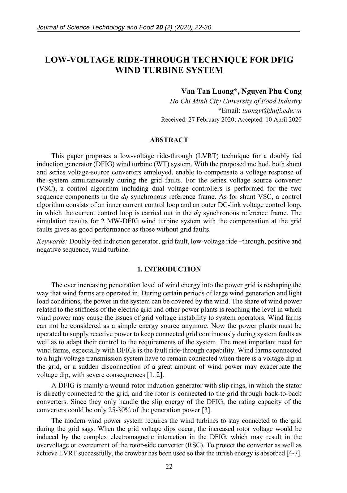
This paper proposes a low-voltage ride-through (LVRT) technique for a doubly fed
induction generator (DFIG) wind turbine (WT) system. With the proposed method, both shunt
and series voltage-source converters employed, enable to compensate a voltage response of
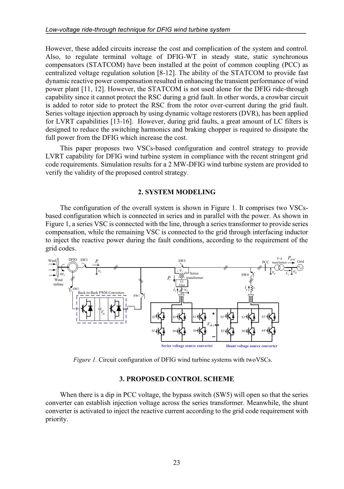
the system simultaneously during the grid faults. For the series voltage source converter
(VSC), a control algorithm including dual voltage controllers is performed for the two
sequence components in the dq synchronous reference frame. As for shunt VSC, a control
algorithm consists of an inner current control loop and an outer DC-link voltage control loop,
in which the current control loop is carried out in the dq synchronous reference frame. The
simulation results for 2 MW-DFIG wind turbine system with the compensation at the grid
faults gives as good performance as those without grid faults.
Trang 1
Trang 2
Trang 3
Trang 4
Trang 5
Trang 6
Trang 7
Trang 8
Trang 9
Tóm tắt nội dung tài liệu: Low - Voltage ride - through technique for dfig wind turbine system
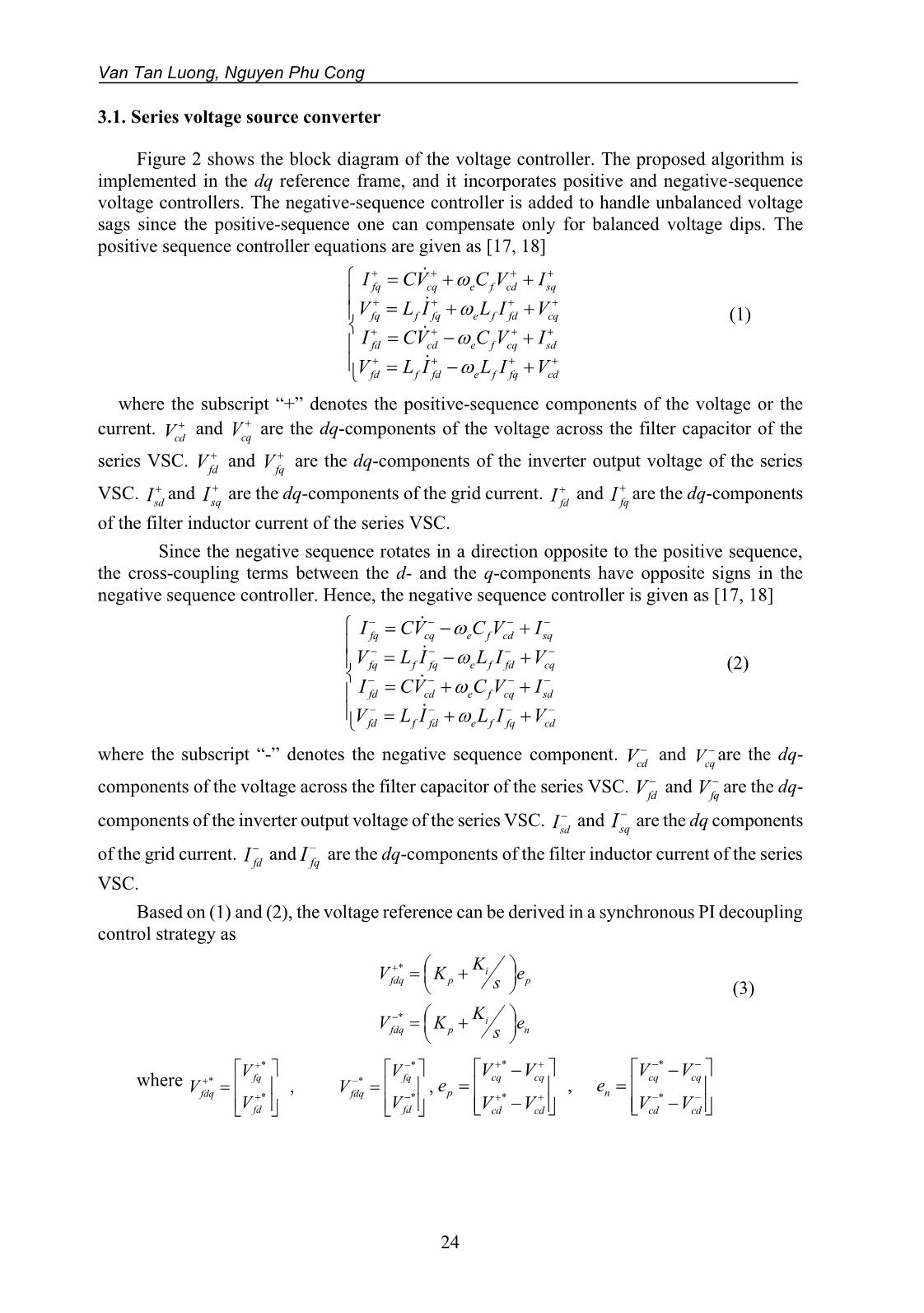
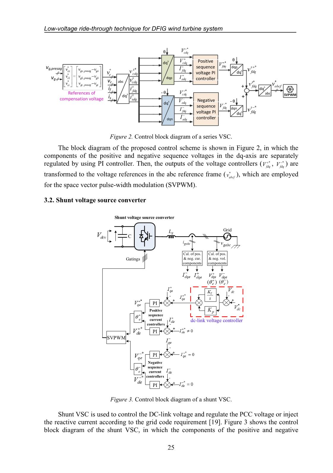
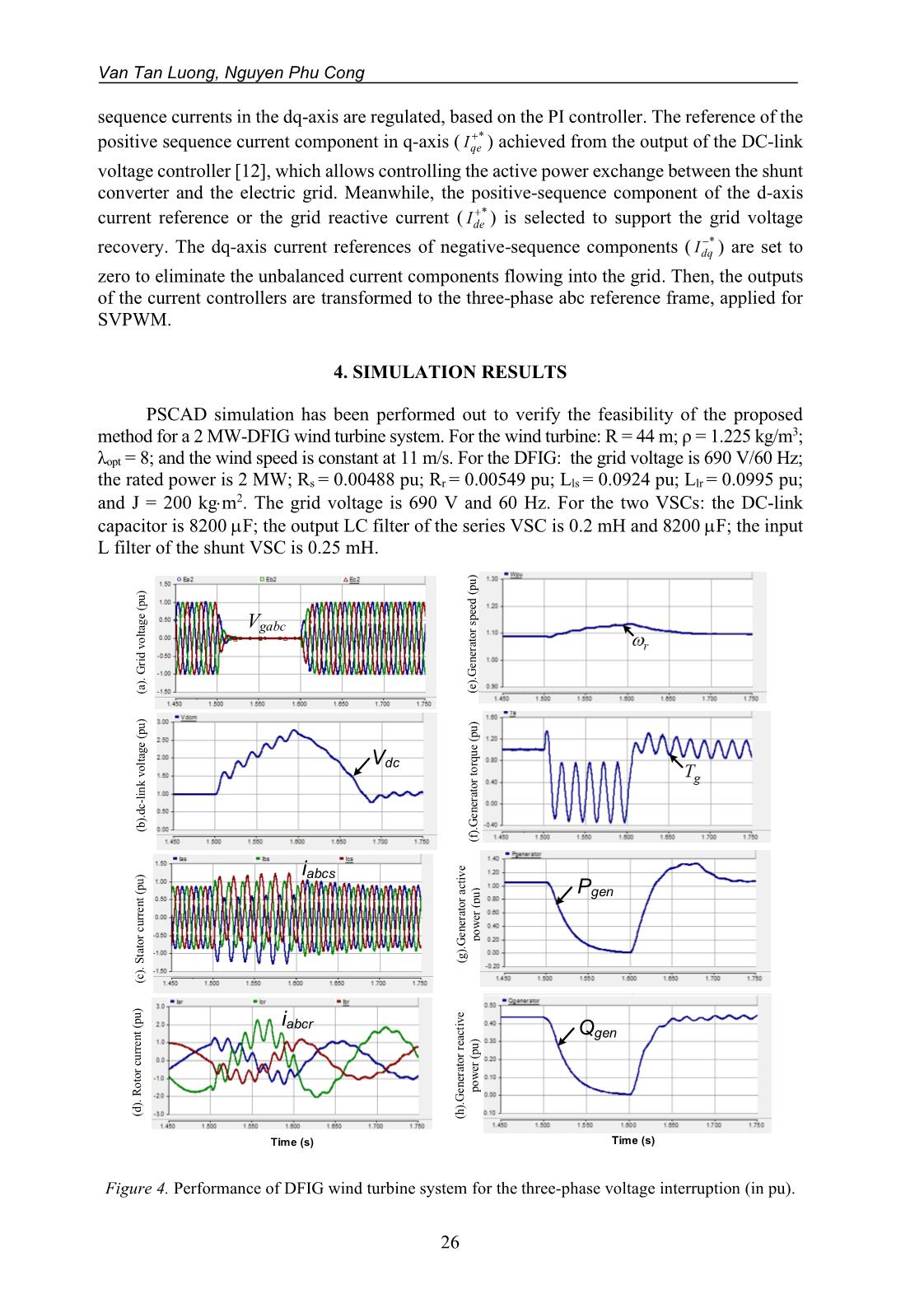
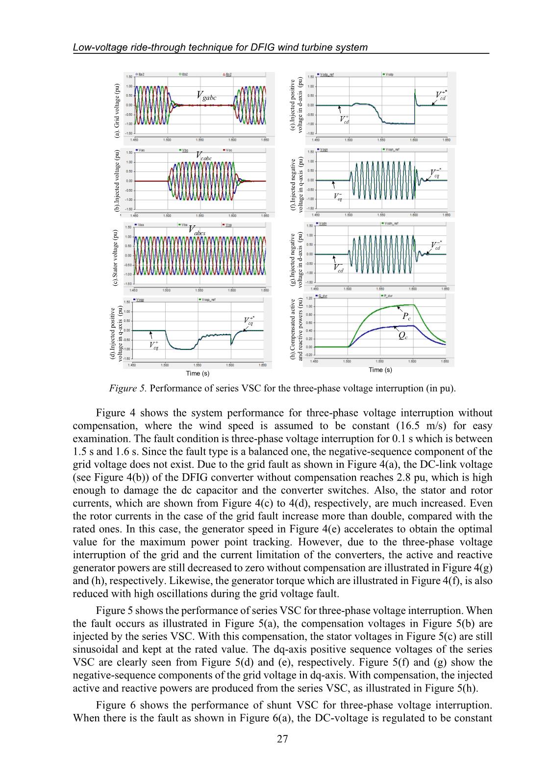
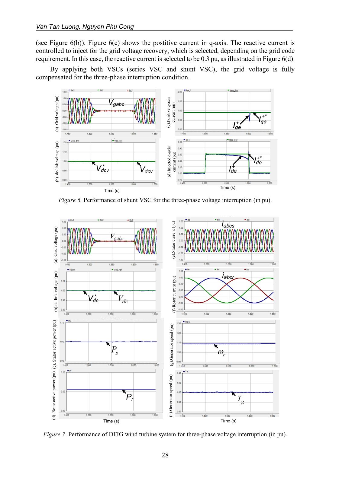
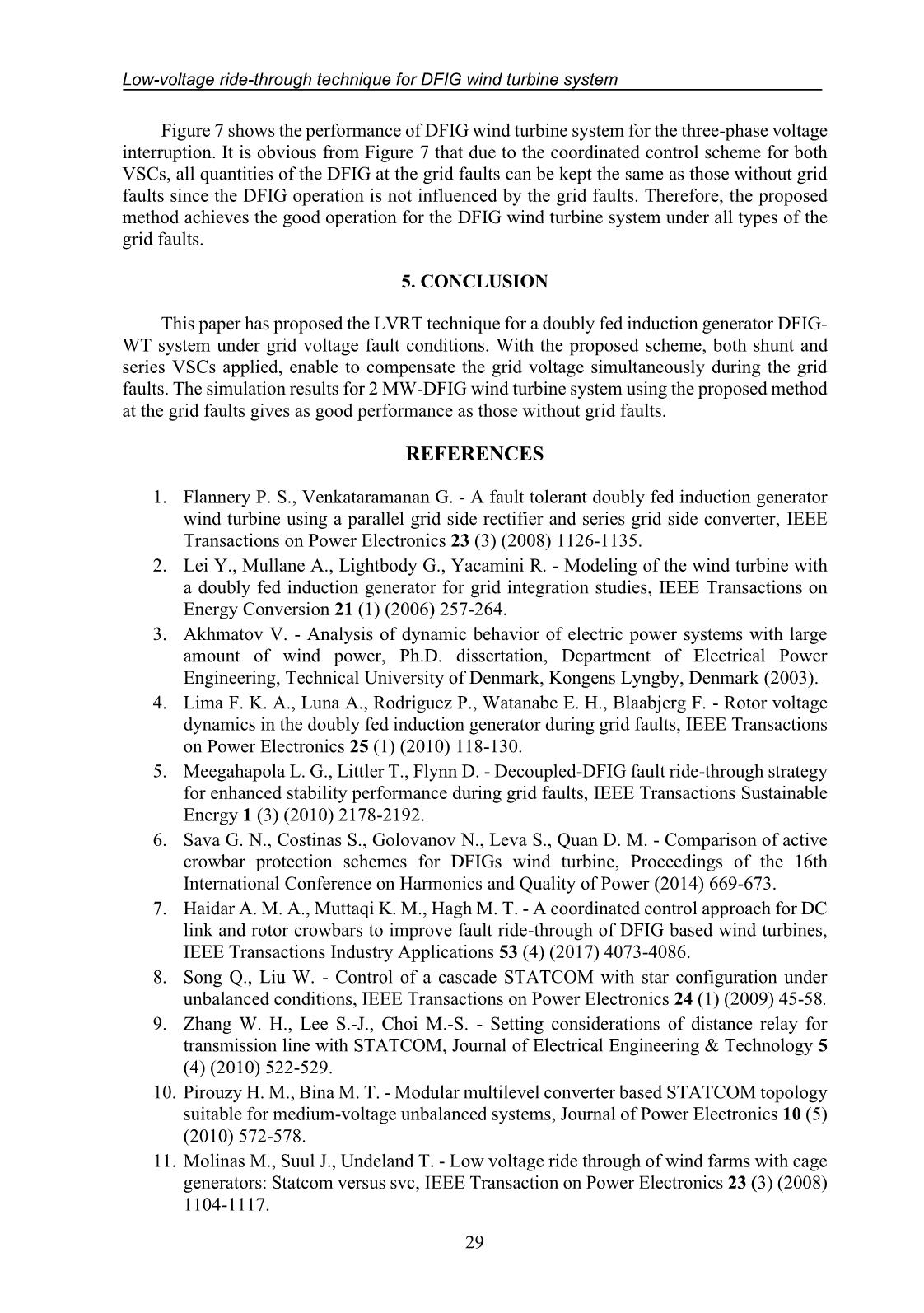
n (1) and (2), the voltage reference can be derived in a synchronous PI decoupling control strategy as * * i fdq p p i fdq p n K V K e s K V K e s + − = + = + (3) where * * * * * * , , fq fq fdq fdq fd fd V V V V V V + − + − + − = = * * * * , cq cq cq cq p n cd cd cd cd V V V V e e V V V V + + − − + + − − − − = = − − Low-voltage ride-through technique for DFIG wind turbine system 25 SVPWM θ dqp is if vc abc Positive sequence voltage PI controller Negative sequence voltage PI controller - θ θ dqp - θ dqn + + dqs dqn abc dqs dqs dqs dqs dqs vg vg,presag References of compensation voltage Figure 2. Control block diagram of a series VSC. The block diagram of the proposed control scheme is shown in Figure 2, in which the components of the positive and negative sequence voltages in the dq-axis are separately regulated by using PI controller. Then, the outputs of the voltage controllers ( * fdqV + , * fdqV − ) are transformed to the voltage references in the abc reference frame ( * abcfv ), which are employed for the space vector pulse-width modulation (SVPWM). 3.2. Shunt voltage source converter C + - Gatings Cal. of pos. & neg. cur. components Cal. of pos. & neg. vol. components Lg SVPWM Grid PI PI + - + - PI PI + - + - Negative sequence current controllers Positive sequence current controllers Shunt voltage source converter e e e e dc-link voltage controller Figure 3. Control block diagram of a shunt VSC. Shunt VSC is used to control the DC-link voltage and regulate the PCC voltage or inject the reactive current according to the grid code requirement [19]. Figure 3 shows the control block diagram of the shunt VSC, in which the components of the positive and negative Van Tan Luong, Nguyen Phu Cong 26 sequence currents in the dq-axis are regulated, based on the PI controller. The reference of the positive sequence current component in q-axis ( *qeI + ) achieved from the output of the DC-link voltage controller [12], which allows controlling the active power exchange between the shunt converter and the electric grid. Meanwhile, the positive-sequence component of the d-axis current reference or the grid reactive current ( *deI + ) is selected to support the grid voltage recovery. The dq-axis current references of negative-sequence components ( *dqI − ) are set to zero to eliminate the unbalanced current components flowing into the grid. Then, the outputs of the current controllers are transformed to the three-phase abc reference frame, applied for SVPWM. 4. SIMULATION RESULTS PSCAD simulation has been performed out to verify the feasibility of the proposed method for a 2 MW-DFIG wind turbine system. For the wind turbine: R = 44 m; ρ = 1.225 kg/m3; λopt = 8; and the wind speed is constant at 11 m/s. For the DFIG: the grid voltage is 690 V/60 Hz; the rated power is 2 MW; Rs = 0.00488 pu; Rr = 0.00549 pu; Lls = 0.0924 pu; Llr = 0.0995 pu; and J = 200 kgm2. The grid voltage is 690 V and 60 Hz. For the two VSCs: the DC-link capacitor is 8200 F; the output LC filter of the series VSC is 0.2 mH and 8200 F; the input L filter of the shunt VSC is 0.25 mH. (a ). G ri d v o lt ag e (p u ) (b ). d c- li n k v o lt ag e ( p u ) (f ). G e n er at o r to rq u e (p u ) (e ). G e n er at o r sp ee d ( p u ) (c ). S ta to r c u rr e n t (p u ) (d ). R o to r cu rr e n t (p u ) Time (s) Vgabc Vdc iabcs iabcr (g ). G e n er at o r a ct iv e p o w er ( p u ) Pgen (h ). G e n er at o r re ac ti v e p o w er ( p u ) Time (s) Qgen Figure 4. Performance of DFIG wind turbine system for the three-phase voltage interruption (in pu). Low-voltage ride-through technique for DFIG wind turbine system 27 (a ). G ri d v o lt ag e (p u ) (c ). S ta to r v o lt a g e (p u ) (b ). In je ct e d v o lt ag e ( p u ) (d ). In je ct e d p o si ti v e v o lt ag e in q -a x is (p u ) (f ). In je ct e d n eg at iv e v o lt ag e in q -a x is (p u ) (g ). In je ct e d n eg at iv e v o lt ag e in d -a x is (p u ) (h ). C o m p en sa te d a ct iv e an d r ea c ti v e p o w e rs ( p u ) (e ). In je ct e d p o si ti v e v o lt ag e in d -a x is (p u ) Time (s) Time (s) Pc Qc Vgabc Figure 5. Performance of series VSC for the three-phase voltage interruption (in pu). Figure 4 shows the system performance for three-phase voltage interruption without compensation, where the wind speed is assumed to be constant (16.5 m/s) for easy examination. The fault condition is three-phase voltage interruption for 0.1 s which is between 1.5 s and 1.6 s. Since the fault type is a balanced one, the negative-sequence component of the grid voltage does not exist. Due to the grid fault as shown in Figure 4(a), the DC-link voltage (see Figure 4(b)) of the DFIG converter without compensation reaches 2.8 pu, which is high enough to damage the dc capacitor and the converter switches. Also, the stator and rotor currents, which are shown from Figure 4(c) to 4(d), respectively, are much increased. Even the rotor currents in the case of the grid fault increase more than double, compared with the rated ones. In this case, the generator speed in Figure 4(e) accelerates to obtain the optimal value for the maximum power point tracking. However, due to the three-phase voltage interruption of the grid and the current limitation of the converters, the active and reactive generator powers are still decreased to zero without compensation are illustrated in Figure 4(g) and (h), respectively. Likewise, the generator torque which are illustrated in Figure 4(f), is also reduced with high oscillations during the grid voltage fault. Figure 5 shows the performance of series VSC for three-phase voltage interruption. When the fault occurs as illustrated in Figure 5(a), the compensation voltages in Figure 5(b) are injected by the series VSC. With this compensation, the stator voltages in Figure 5(c) are still sinusoidal and kept at the rated value. The dq-axis positive sequence voltages of the series VSC are clearly seen from Figure 5(d) and (e), respectively. Figure 5(f) and (g) show the negative-sequence components of the grid voltage in dq-axis. With compensation, the injected active and reactive powers are produced from the series VSC, as illustrated in Figure 5(h). Figure 6 shows the performance of shunt VSC for three-phase voltage interruption. When there is the fault as shown in Figure 6(a), the DC-voltage is regulated to be constant Van Tan Luong, Nguyen Phu Cong 28 (see Figure 6(b)). Figure 6(c) shows the postitive current in q-axis. The reactive current is controlled to inject for the grid voltage recovery, which is selected, depending on the grid code requirement. In this case, the reactive current is selected to be 0.3 pu, as illustrated in Figure 6(d). By applying both VSCs (series VSC and shunt VSC), the grid voltage is fully compensated for the three-phase interruption condition. (a ). G ri d v o lt ag e (p u ) (b ). d c- li n k v o lt ag e (p u ) Vdcv * Time (s) Time (s) (c ). P o si ti v e q -a x is cu rr en t (p u ) Iqe Iqe +* + Vdcv Vgabc (d ). In je ct e d d -a x is cu rr en t (p u ) Ide +* Ide + Figure 6. Performance of shunt VSC for the three-phase voltage interruption (in pu). (c ). S ta to r a ct iv e p o w er ( p u ) (b ). d c -l in k v o lt ag e ( p u ) (g ). G e n er at o r sp ee d ( p u ) Time (s) (d ). R o to r ac ti v e p o w er ( p u ) Time (s) (e ). S ta to r c u rr e n t (p u ) (h ). G e n er at o r sp ee d ( p u ) (f ) R o to r cu rr e n t (p u ) (a ). G ri d v o lt ag e (p u ) Pr iabcs iabcr Vdc * Vgabc Figure 7. Performance of DFIG wind turbine system for three-phase voltage interruption (in pu). Low-voltage ride-through technique for DFIG wind turbine system 29 Figure 7 shows the performance of DFIG wind turbine system for the three-phase voltage interruption. It is obvious from Figure 7 that due to the coordinated control scheme for both VSCs, all quantities of the DFIG at the grid faults can be kept the same as those without grid faults since the DFIG operation is not influenced by the grid faults. Therefore, the proposed method achieves the good operation for the DFIG wind turbine system under all types of the grid faults. 5. CONCLUSION This paper has proposed the LVRT technique for a doubly fed induction generator DFIG- WT system under grid voltage fault conditions. With the proposed scheme, both shunt and series VSCs applied, enable to compensate the grid voltage simultaneously during the grid faults. The simulation results for 2 MW-DFIG wind turbine system using the proposed method at the grid faults gives as good performance as those without grid faults. REFERENCES 1. Flannery P. S., Venkataramanan G. - A fault tolerant doubly fed induction generator wind turbine using a parallel grid side rectifier and series grid side converter, IEEE Transactions on Power Electronics 23 (3) (2008) 1126-1135. 2. Lei Y., Mullane A., Lightbody G., Yacamini R. - Modeling of the wind turbine with a doubly fed induction generator for grid integration studies, IEEE Transactions on Energy Conversion 21 (1) (2006) 257-264. 3. Akhmatov V. - Analysis of dynamic behavior of electric power systems with large amount of wind power, Ph.D. dissertation, Department of Electrical Power Engineering, Technical University of Denmark, Kongens Lyngby, Denmark (2003). 4. Lima F. K. A., Luna A., Rodriguez P., Watanabe E. H., Blaabjerg F. - Rotor voltage dynamics in the doubly fed induction generator during grid faults, IEEE Transactions on Power Electronics 25 (1) (2010) 118-130. 5. Meegahapola L. G., Littler T., Flynn D. - Decoupled-DFIG fault ride-through strategy for enhanced stability performance during grid faults, IEEE Transactions Sustainable Energy 1 (3) (2010) 2178-2192. 6. Sava G. N., Costinas S., Golovanov N., Leva S., Quan D. M. - Comparison of active crowbar protection schemes for DFIGs wind turbine, Proceedings of the 16th International Conference on Harmonics and Quality of Power (2014) 669-673. 7. Haidar A. M. A., Muttaqi K. M., Hagh M. T. - A coordinated control approach for DC link and rotor crowbars to improve fault ride-through of DFIG based wind turbines, IEEE Transactions Industry Applications 53 (4) (2017) 4073-4086. 8. Song Q., Liu W. - Control of a cascade STATCOM with star configuration under unbalanced conditions, IEEE Transactions on Power Electronics 24 (1) (2009) 45-58. 9. Zhang W. H., Lee S.-J., Choi M.-S. - Setting considerations of distance relay for transmission line with STATCOM, Journal of Electrical Engineering & Technology 5 (4) (2010) 522-529. 10. Pirouzy H. M., Bina M. T. - Modular multilevel converter based STATCOM topology suitable for medium-voltage unbalanced systems, Journal of Power Electronics 10 (5) (2010) 572-578. 11. Molinas M., Suul J., Undeland T. - Low voltage ride through of wind farms with cage generators: Statcom versus svc, IEEE Transaction on Power Electronics 23 (3) (2008) 1104-1117. Van Tan Luong, Nguyen Phu Cong 30 12. Zou Y., Elbuluk M., Sozer Y. - Simulation comparisons and implementation of induction generator wind power systems, IEEE Transactions Industry Application 49 (3) (2013) 1119-1128. 13. Leon A., Farias M., Battaiotto P., Solsona J., Valla M. - Control strategy of a DVR to improve stability in wind farms using squirrel-cage induction generators, IEEE Transactions on Power System 26 (3) (2011) 1609-1617. 14. Ramirez D., Martinez S., Platero C., Blazquez F., de Castro R. - Low-voltage ride- through capability for wind generators based on dynamic voltage restorers, IEEE Transactions on Energy Conversion 26 (1) (2011) 195-203. 15. El Moursi M., Goweily K., Kirtley J., and Abdel-Rahman M. - Application of series voltage boosting schemes for enhanced fault ride-through performance of fixed speed wind turbines, IEEE Transactions Power Delivery 29 (1) (2014) 61-71. 16. Wessels C., Gebhardt F., and Fuchs F. - Fault ride-through of a DFIG wind turbine using a dynamic voltage restorer during symmetrical and asymmetrical grid faults, IEEE Transactions on Power Electronics 26 (3) (2011) 807-815. 17. Ibrahim A. O., Nguyen T. H., Lee D.-C., Kim S.-C. - A fault ridethrough technique of DFIG wind turbine systems using dynamic voltage restorers, IEEE Transactions on Energy Conversion 26 (3) (2011) 871-882. 18. Van T. L., Nguyen N. M. D., Toi L. T., Trang T. T. - Advanced control strategy of dynamic voltage restorers for distribution system using sliding mode control input-ouput feedback linearization, Lecture Notes in Electrical Engineering 465 (2017) 521-531. 19. Van T. L. and Ho V. C. - Enhanced fault ride-through capability of DFIG wind turbine systems considering grid-side converter as STATCOM, Lecture Notes in Electrical Engineering 371 (2015) 185-196. TÓM TẮT KỸ THUẬT LƯỚT QUA ĐIỆN ÁP THẤP CHO HỆ THỐNG TUA-BIN GIÓ DÙNG MÁY PHÁT DFIG Văn Tấn Lượng*, Nguyễn Phú Công Trường Đại học Công nghiệp Thực phẩm TP.HCM *Email: luongvt@hufi.edu.vn Bài báo này đề xuất một kỹ thuật lướt qua điện áp thấp (LVRT) cho một hệ thống tua- bin gió dùng máy phát không đồng bộ nguồn kép (DFIG). Với phương pháp đề xuất, cả bộ chuyển đổi nguồn điện áp mắc nối tiếp và mắc song song được sử dụng, cho phép bù đồng thời đáp ứng điện áp của hệ thống trong trường hợp sự cố lưới điện. Đối với bộ chuyển đổi nguồn điện áp mắc nối tiếp (VSC), thuật toán điều khiển bao gồm bộ điều khiển điện áp kép được thực hiện cho hai thành phần thứ tự thuận và nghịch trong hệ tọa độ quay dq. Đối với bộ VSC mắc song song, thuật toán điều khiển bao gồm vòng lặp điều khiển dòng điện bên trong và vòng lặp điều khiển điện áp DC-link bên ngoài, trong đó vòng lặp điều khiển dòng điện được thực hiện trong hệ tọa độ quay dq. Kết quả mô phỏng đối với hệ thống tua-bin gió dùng máy phát DFIG công suất 2 MW đã chứng tỏ rằng phương pháp đề xuất cho kết quả vận hành tốt như trong trường hợp không có sự cố điện áp lưới. Từ khóa: Máy phát không đồng bộ nguồn kép, sự cố lưới, lướt qua điện áp thấp, thành phần thứ tự thuận và nghịch, tua-bin gió.
File đính kèm:
 low_voltage_ride_through_technique_for_dfig_wind_turbine_sys.pdf

