Intelligent ann - based load - frequency control strategies for an interconnected hydropower system
Load frequency control (LFC) is one of the most important control
problems in electric power grids, including hydropower systems. The major
functions of this control strategy for an interconnected hydropower network are to
maintain the net frequency at a nominal value and the tie-line power flow at a
scheduled value. Together with a fast development of science and technology,
conventional LFC regulators such as PID have been replaced with intelligent
controllers. This paper introduces such two typical controllers based on artificial
neural networks, namely ANN-based NARMA and ANN- based MRAC. Numerical
simulation results obtained by such two controllers when solving the LFC of a twocontrol-area interconnected hydropower grid have verified the feasibility and
superiority of the proposed control strategies.
Trang 1
Trang 2
Trang 3
Trang 4
Trang 5
Trang 6
Trang 7
Trang 8
Trang 9
Trang 10
Tải về để xem bản đầy đủ
Tóm tắt nội dung tài liệu: Intelligent ann - based load - frequency control strategies for an interconnected hydropower system
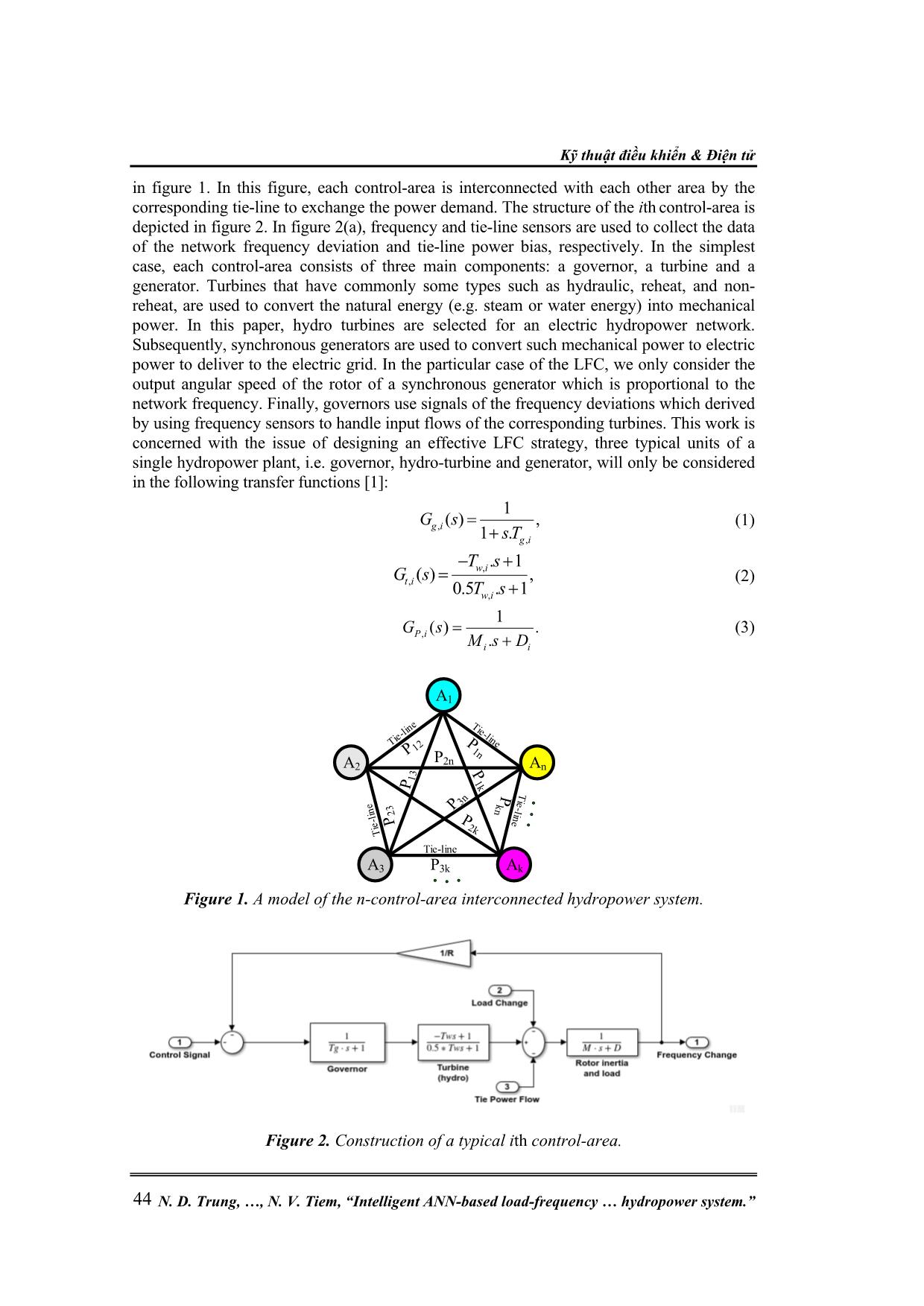
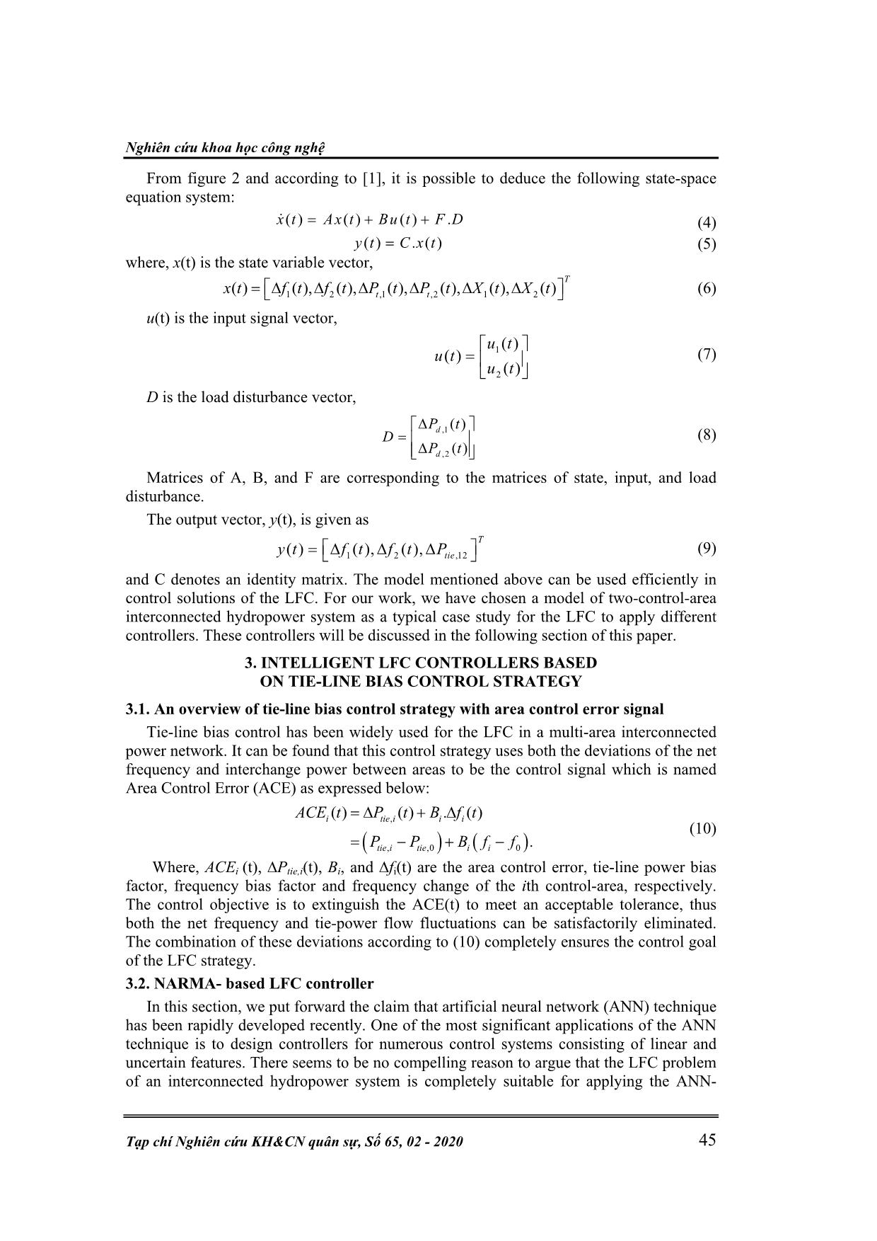
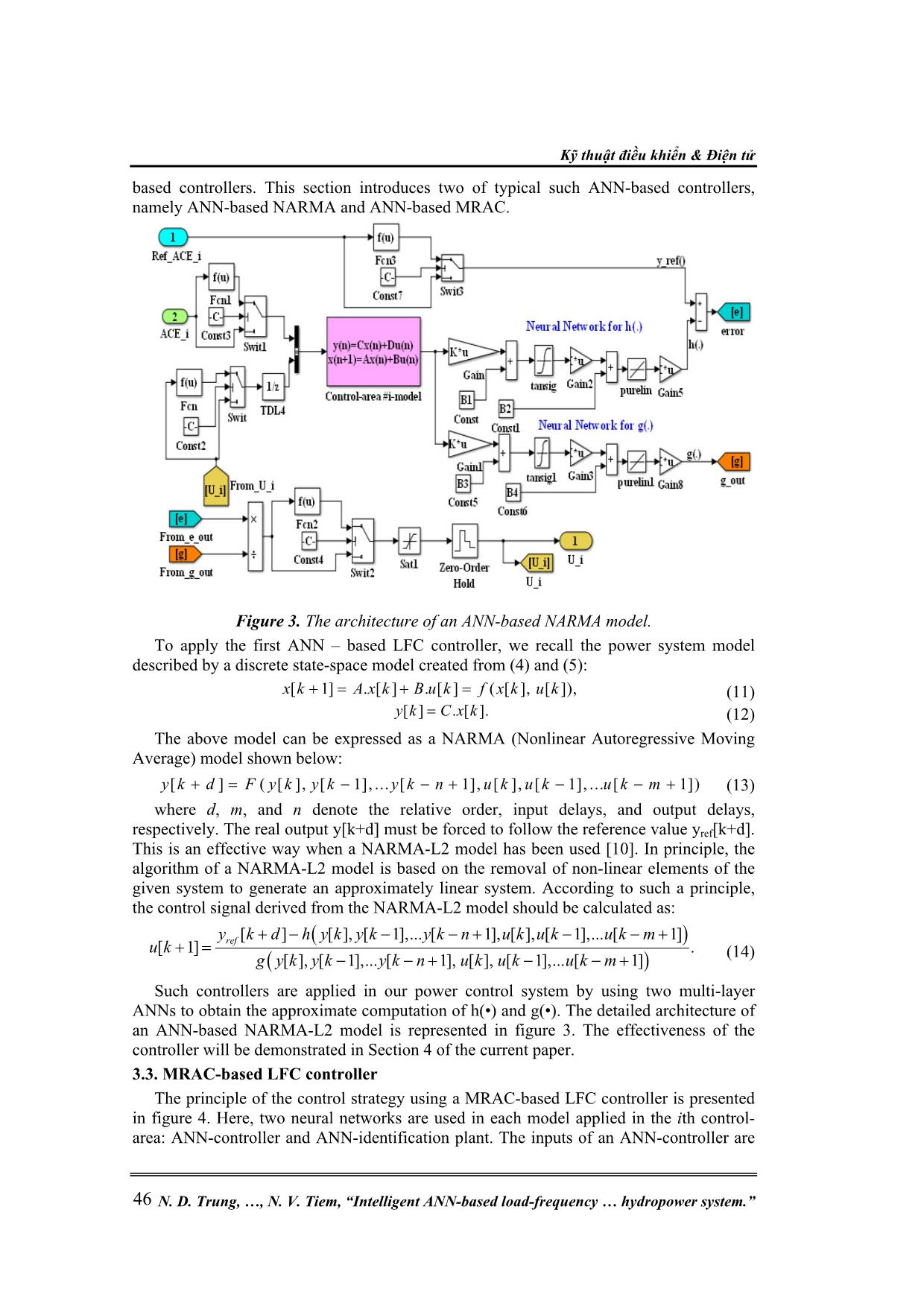
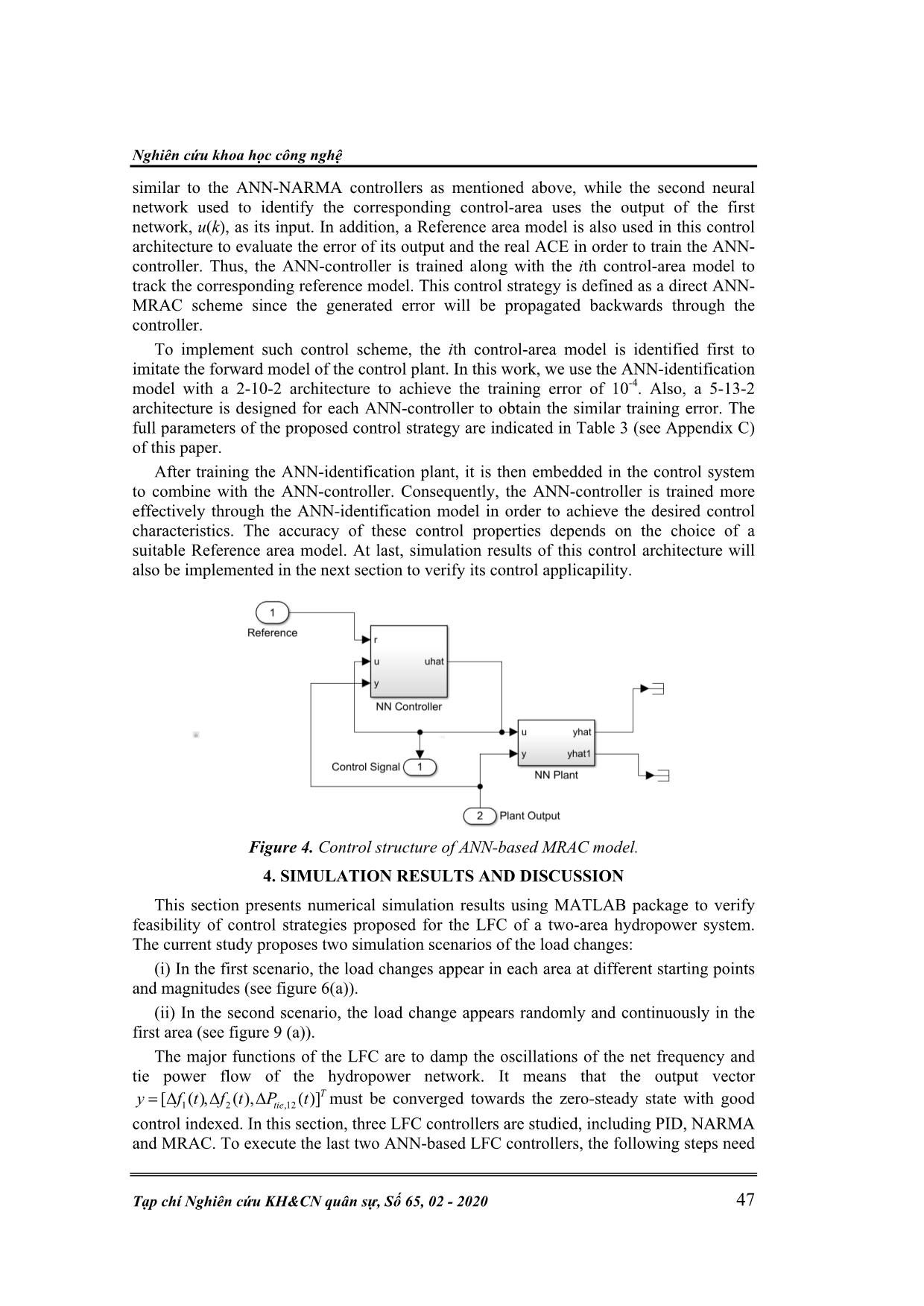
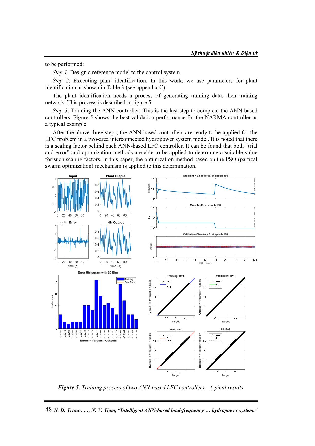
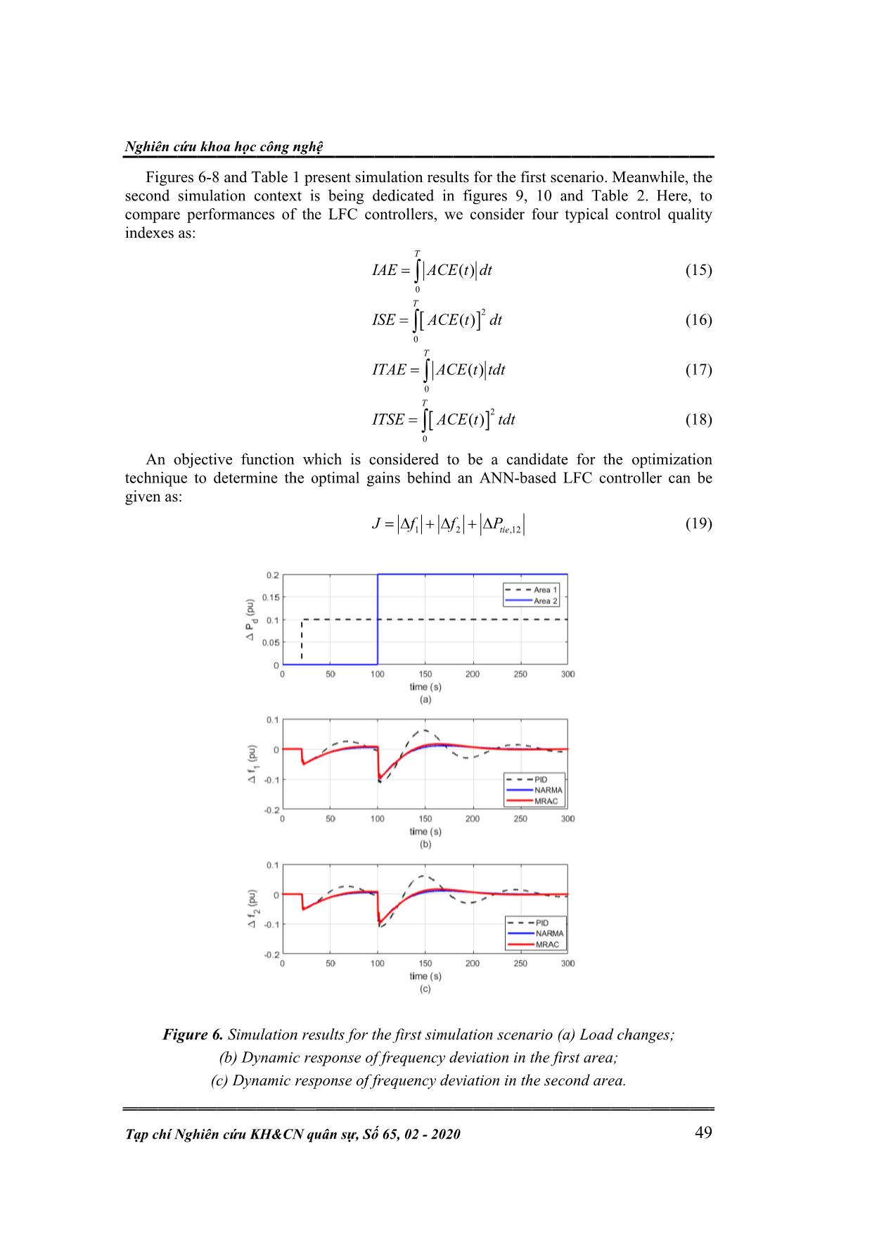
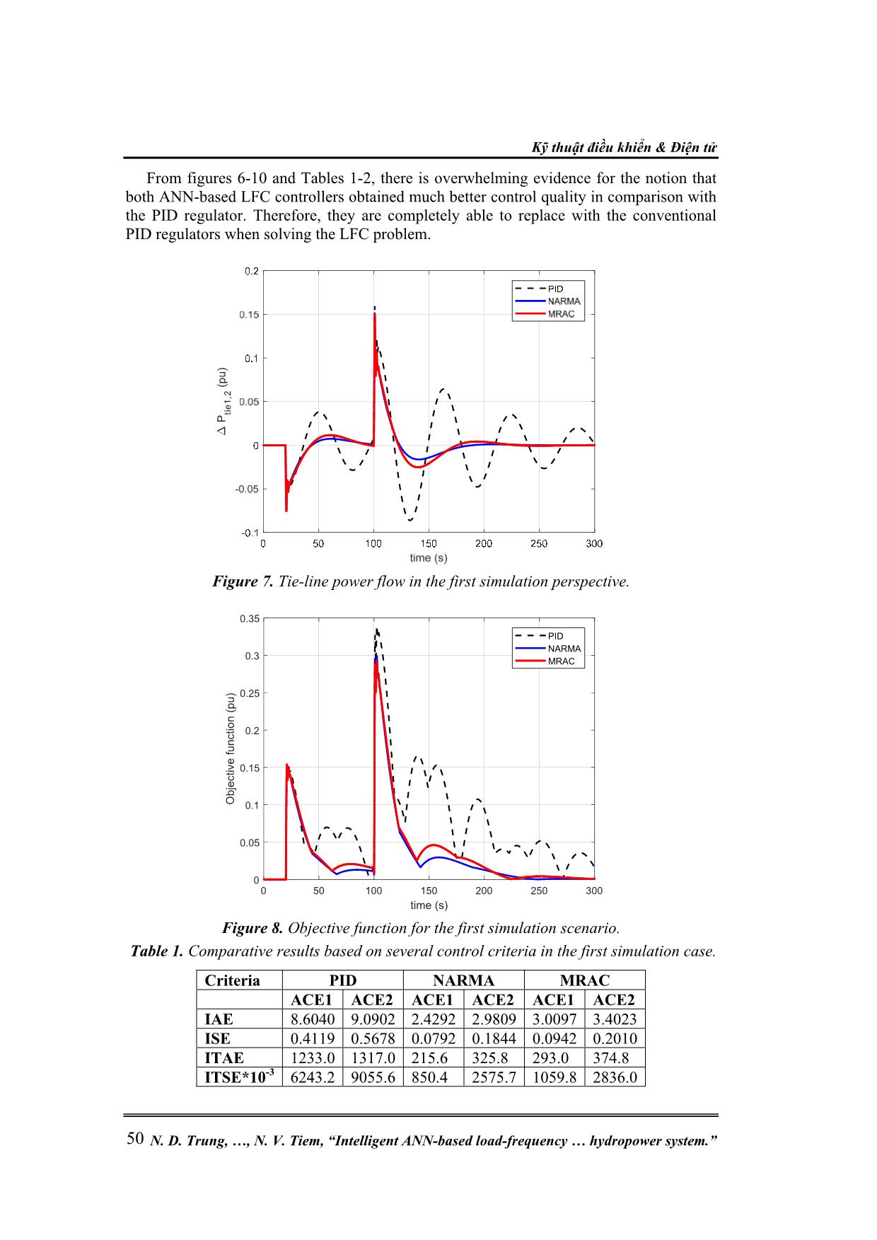
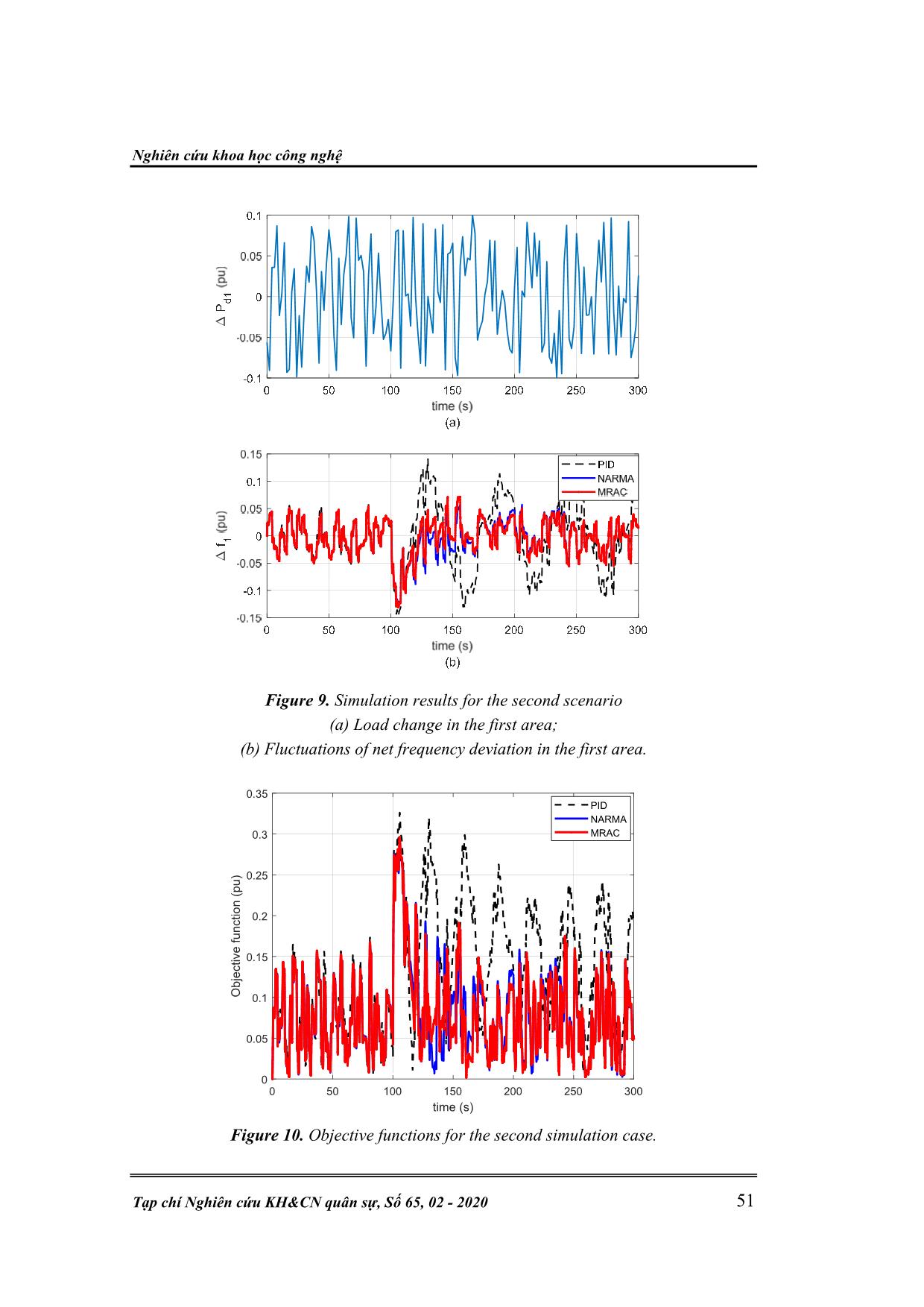
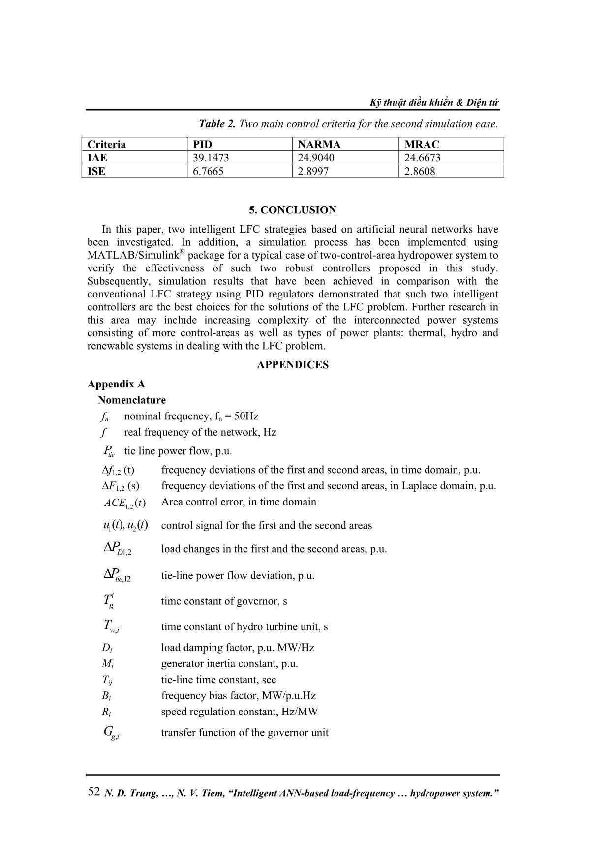
itable for applying the ANN- Kỹ thuật điều khiển & Điện tử N. D. Trung, , N. V. Tiem, “Intelligent ANN-based load-frequency hydropower system.” 46 based controllers. This section introduces two of typical such ANN-based controllers, namely ANN-based NARMA and ANN-based MRAC. Figure 3. The architecture of an ANN-based NARMA model. To apply the first ANN – based LFC controller, we recall the power system model described by a discrete state-space model created from (4) and (5): [ 1] . [ ] . [ ] ( [ ], [ ]),x k A x k B u k f x k u k (11) [ ] . [ ].y k C x k (12) The above model can be expressed as a NARMA (Nonlinear Autoregressive Moving Average) model shown below: [ ] ( [ ], [ 1], ... [ 1], [ ], [ 1], ... [ 1])y k d F y k y k y k n u k u k u k m (13) where d, m, and n denote the relative order, input delays, and output delays, respectively. The real output y[k+d] must be forced to follow the reference value yref[k+d]. This is an effective way when a NARMA-L2 model has been used [10]. In principle, the algorithm of a NARMA-L2 model is based on the removal of non-linear elements of the given system to generate an approximately linear system. According to such a principle, the control signal derived from the NARMA-L2 model should be calculated as: [ ] [ ], [ 1],... [ 1], [ ], [ 1],... [ 1] [ 1] . [ ], [ 1],... [ 1], [ ], [ 1],... [ 1] refy k d h y k y k y k n u k u k u k m u k g y k y k y k n u k u k u k m (14) Such controllers are applied in our power control system by using two multi-layer ANNs to obtain the approximate computation of h(•) and g(•). The detailed architecture of an ANN-based NARMA-L2 model is represented in figure 3. The effectiveness of the controller will be demonstrated in Section 4 of the current paper. 3.3. MRAC-based LFC controller The principle of the control strategy using a MRAC-based LFC controller is presented in figure 4. Here, two neural networks are used in each model applied in the ith control- area: ANN-controller and ANN-identification plant. The inputs of an ANN-controller are Nghiên cứu khoa học công nghệ Tạp chí Nghiên cứu KH&CN quân sự, Số 65, 02 - 2020 47 similar to the ANN-NARMA controllers as mentioned above, while the second neural network used to identify the corresponding control-area uses the output of the first network, u(k), as its input. In addition, a Reference area model is also used in this control architecture to evaluate the error of its output and the real ACE in order to train the ANN- controller. Thus, the ANN-controller is trained along with the ith control-area model to track the corresponding reference model. This control strategy is defined as a direct ANN- MRAC scheme since the generated error will be propagated backwards through the controller. To implement such control scheme, the ith control-area model is identified first to imitate the forward model of the control plant. In this work, we use the ANN-identification model with a 2-10-2 architecture to achieve the training error of 10-4. Also, a 5-13-2 architecture is designed for each ANN-controller to obtain the similar training error. The full parameters of the proposed control strategy are indicated in Table 3 (see Appendix C) of this paper. After training the ANN-identification plant, it is then embedded in the control system to combine with the ANN-controller. Consequently, the ANN-controller is trained more effectively through the ANN-identification model in order to achieve the desired control characteristics. The accuracy of these control properties depends on the choice of a suitable Reference area model. At last, simulation results of this control architecture will also be implemented in the next section to verify its control applicapility. Figure 4. Control structure of ANN-based MRAC model. 4. SIMULATION RESULTS AND DISCUSSION This section presents numerical simulation results using MATLAB package to verify feasibility of control strategies proposed for the LFC of a two-area hydropower system. The current study proposes two simulation scenarios of the load changes: (i) In the first scenario, the load changes appear in each area at different starting points and magnitudes (see figure 6(a)). (ii) In the second scenario, the load change appears randomly and continuously in the first area (see figure 9 (a)). The major functions of the LFC are to damp the oscillations of the net frequency and tie power flow of the hydropower network. It means that the output vector 1 2 ,12[ ( ), ( ), ( )] T tiey f t f t P t must be converged towards the zero-steady state with good control indexed. In this section, three LFC controllers are studied, including PID, NARMA and MRAC. To execute the last two ANN-based LFC controllers, the following steps need Kỹ thuật điều khiển & Điện tử N. D. Trung, , N. V. Tiem, “Intelligent ANN-based load-frequency hydropower system.” 48 to be performed: Step 1: Design a reference model to the control system. Step 2: Executing plant identification. In this work, we use parameters for plant identification as shown in Table 3 (see appendix C). The plant identification needs a process of generating training data, then training network. This process is described in figure 5. Step 3: Training the ANN controller. This is the last step to complete the ANN-based controllers. Figure 5 shows the best validation performance for the NARMA controller as a typical example. After the above three steps, the ANN-based controllers are ready to be applied for the LFC problem in a two-area interconnected hydropower system model. It is noted that there is a scaling factor behind each ANN-based LFC controller. It can be found that both “trial and error” and optimization methods are able to be applied to determine a suitable value for such scaling factors. In this paper, the optimization method based on the PSO (partical swarm optimization) mechanism is applied to this determination. Figure 5. Training process of two ANN-based LFC controllers – typical results. 0 20 40 60 80 -1 -0.5 0 0.5 1 Input 0 20 40 60 80 0 0.2 0.4 0.6 0.8 Plant Output 0 20 40 60 80 time (s) -2 -1 0 1 2 10-3 Error 0 20 40 60 80 time (s) 0 0.2 0.4 0.6 0.8 NN Output Nghiên c Tạp chí Nghi second simulation context is being dedicated in compare performances of the LFC controllers, indexes technique to determine the optimal gains behind given as: Figures 6 An objective function which is considered to be Figure 6. ứu khoa học công nghệ as: ên c -8 and Table 1 present simulation results for the first scenario. Meanwhile, the (c) Dynamic response of frequency deviation in the second area. ứu KH&CN Simulation results for the first simulation scenario (b) Dynamic response of frequency deviation in the first area; quân s ự, Số IAE ACE t dt ISE ACE t dt ITAE ACE t tdt ITSE ACE t tdt J f f P 65 , 02 0 T - 20 0 T 0 T 0 T 1 2 ,12 20 we consider four typ figures 9, 10 and Table 2. Here, ( ) ( ) ( ) ( ) an ANN 2 2 a candidate for the optimization tie -based LFC controller can be (a) Load changes; ical control quality (1 (1 (17 (18 (19 49 to 5) 6) ) ) ) Kỹ thuật điều khiển & Điện tử N. D. Trung, , N. V. Tiem, “Intelligent ANN-based load-frequency hydropower system.” 50 From figures 6-10 and Tables 1-2, there is overwhelming evidence for the notion that both ANN-based LFC controllers obtained much better control quality in comparison with the PID regulator. Therefore, they are completely able to replace with the conventional PID regulators when solving the LFC problem. Figure 7. Tie-line power flow in the first simulation perspective. Figure 8. Objective function for the first simulation scenario. Table 1. Comparative results based on several control criteria in the first simulation case. P ti e 1 ,2 (p u ) 0 50 100 150 200 250 300 time (s) 0 0.05 0.1 0.15 0.2 0.25 0.3 0.35 O b je ct iv e f u n ct io n ( p u ) PID NARMA MRAC Criteria PID NARMA MRAC ACE1 ACE2 ACE1 ACE2 ACE1 ACE2 IAE 8.6040 9.0902 2.4292 2.9809 3.0097 3.4023 ISE 0.4119 0.5678 0.0792 0.1844 0.0942 0.2010 ITAE 1233.0 1317.0 215.6 325.8 293.0 374.8 ITSE*10-3 6243.2 9055.6 850.4 2575.7 1059.8 2836.0 Nghiên cứu khoa học công nghệ Tạp chí Nghiên cứu KH&CN quân sự, Số 65, 02 - 2020 51 Figure 9. Simulation results for the second scenario (a) Load change in the first area; (b) Fluctuations of net frequency deviation in the first area. Figure 10. Objective functions for the second simulation case. 0 50 100 150 200 250 300 time (s) 0 0.05 0.1 0.15 0.2 0.25 0.3 0.35 O b je ct iv e f u n ct io n ( p u ) PID NARMA MRAC Kỹ thuật điều khiển & Điện tử N. D. Trung, , N. V. Tiem, “Intelligent ANN-based load-frequency hydropower system.” 52 Table 2. Two main control criteria for the second simulation case. 5. CONCLUSION In this paper, two intelligent LFC strategies based on artificial neural networks have been investigated. In addition, a simulation process has been implemented using MATLAB/Simulink® package for a typical case of two-control-area hydropower system to verify the effectiveness of such two robust controllers proposed in this study. Subsequently, simulation results that have been achieved in comparison with the conventional LFC strategy using PID regulators demonstrated that such two intelligent controllers are the best choices for the solutions of the LFC problem. Further research in this area may include increasing complexity of the interconnected power systems consisting of more control-areas as well as types of power plants: thermal, hydro and renewable systems in dealing with the LFC problem. APPENDICES Appendix A Nomenclature fn nominal frequency, fn = 50Hz f real frequency of the network, Hz tieP tie line power flow, p.u. ∆f1,2 (t) frequency deviations of the first and second areas, in time domain, p.u. ∆F1,2 (s) frequency deviations of the first and second areas, in Laplace domain, p.u. 1,2 ( )ACE t Area control error, in time domain 1 2( ), ( )u t u t control signal for the first and the second areas 1,2DP load changes in the first and the second areas, p.u. ,12tieP tie-line power flow deviation, p.u. i gT time constant of governor, s ,w iT time constant of hydro turbine unit, s Di load damping factor, p.u. MW/Hz Mi generator inertia constant, p.u. Tij tie-line time constant, sec Bi frequency bias factor, MW/p.u.Hz Ri speed regulation constant, Hz/MW ,g iG transfer function of the governor unit Criteria PID NARMA MRAC IAE 39.1473 24.9040 24.6673 ISE 6.7665 2.8997 2.8608 Nghiên cứu khoa học công nghệ Tạp chí Nghiên cứu KH&CN quân sự, Số 65, 02 - 2020 53 ,t iG transfer function of the hydro turbine unit ,PiG transfer function of the rotor inertia and load (power system) Appendix B Two-area interconnected power system parameters: 1 2 48.7g gT T s ; 1 2 1w wT T s 1 2 1 2 1 2 1 2 120.513; 0.6; 1; 2.4; 0.0707;r rT T M M D D R R T Load changes: Scenario 1: ,1 ,1 0.1( ) 0.2( ) D D D P pu P P pu at starting times: 20s and 50s. Scenario 2: ∆PD1 is a uniform random number function generates uniformly distributed random numbers over an interval of [-1; 1]. ∆PD2 is the same to ∆PD2 in the first scenario. Appendix C Table 3. Parameters for the proposed two ANN-based controllers. Parameters NARMA MRAC MRC Controller Plant Model Size of Hidden layer 8 15 14 Sampling internal (s) 0.01 0.05 0.05 No. Delayed Ref. inputs N/A 2 N/A No. Delayed Plant inputs 3 N/A 2 No. Delayed Plant outputs 2 2 2 No. Delayed controller outputs N/A 2 N/A Training samples 10000 15000 10000 Training epochs 100 10 30 Training function trainlm trainlm trainlm Trained error 10-5 10-4 10-4 REFERENCES [1]. Kundur P. Power system stability and control. New York, USA: McGraw-Hill, 1994. [2]. Murty PSR. Operation and control in power systems. Hyderabad, India: BS Publications, 2008. [3]. H. Bevrani and T. Hiyama, Intelligent Automatic Generation Control, CRC Press, 2016. [4]. Shashi KP, Soumya RM, Nand K. A literature survey on load-frequency control for conventional and distribution generation power systems. Renewable and Sustainable Energy Reviews 2013; 25: 318-334. Kỹ thuật điều khiển & Điện tử N. D. Trung, , N. V. Tiem, “Intelligent ANN-based load-frequency hydropower system.” 54 [5]. R. C. Dorf and R. H. Bishop, Modern Control Systems, Pearson Prentice Hall, 2008. [6]. R. Verma, S. Pal and S. Sathans, “Intelligent Automatic Generation Control of Two- Area Hydrothermal Power System Using ANN and Fuzzy Logic,” In: 2013 International Conference on Communication Systems and Network Technologies (CSNT), pp. 552-556, 6-8 April 2013. [7]. Bimal KB. Modern power electronics and AC drives. Upper Saddle River, NJ, USA: Prentice Hall PTR, 2002. [8]. Hykin S. Neural network. USA: Mac Miller, 1994. [9]. Norgaard M., Poulsen N. K., Hansen L. K., Ravn O. Neural Networks for Modelling and Control of Dynamic Systems. Springer, 2003. [10]. D. K. Sambariya and V. Nath, "Application of NARMA L2 controller for load frequency control of multi-area power system," 2016 10th International Conference on Intelligent Systems and Control (ISCO), Coimbatore, 2016, pp. 1-7 TÓM TẮT CÁC CHIẾN LƯỢC ĐIỀU KHIỂN TẦN SỐ - PHỤ TẢI THÔNG MINH DỰA TRÊN TRÍ TUỆ NHÂN TẠO CHO MỘT HỆ THỐNG THỦY ĐIỆN LIÊN KẾT Điều khiển tần số tải (LFC) là một trong những bài toán điều khiển quan trọng nhất trong hệ thống điện nói chung và hệ thống nhà máy thủy điện nói riêng. Nhiệm vụ chủ yếu của chiến lược điều khiển này khi áp dụng cho một hệ thống các nhà máy thủy điện liên kết là để duy trì tần số lưới và công suất trao đổi trên đường dây tại các giá trị danh định. Cùng với sự phát triển nhanh chóng của khoa học kỹ thuật, các bộ điều khiển tần số tải truyền thống như PID đã được thay thế bởi các bộ điều khiển thông minh. Bài báo này giới thiệu hai bộ điều khiển thông minh ứng dụng trí tuệ nhân tạo, đó là NARMA và MRAC. Các kết quả mô phỏng đạt được từ việc áp dụng hai bộ điều khiển này cho bài toán kiểm soát tần số phụ tải của một hệ thống thủy điện hai vùng điều khiển liên kết đã chứng tỏ tính khả thi và ưu việt của các chiến lược điều khiển đã đề xuất. Từ khóa: LFC; Hệ thống thủy điện liên kết; Thay đổi tải; Độ lệch tần số; Công suất tro đổi đường dây; Chỉ số chất lượng điều khiển. Received, 13th December, 2019 Revised, 10th January, 2020 Published, 17th February, 2020 Author affiliations: 1 Electric Power University; 2 National Center for Technological Progress; 3University of Transport and Communications. *Corresponding author: trungnd@epu.edu.vn.
File đính kèm:
 intelligent_ann_based_load_frequency_control_strategies_for.pdf

