Improving stability for independent power control of dfig with sfoc and dpc during grid unbalance
This paper presents modified Stator Fed Oriented
Control (SFOC)for Doubly Fed Induction Generator (DFIG) in wind
turbines during grid unbalance,and improves stability by using
Notch filter to eliminate second order harmonic components.The
proposed schemes apply multiple PI controllers with Fuzzy and
anti-windup (PI-F) to obtain commanded rotor currents and also
introduce extra commanded values for rotor currents. Comparison
of the proposed controller with Direct Power Control (DPC) using
Notch filters for improvement during grid voltage unbalance is also
included. The modifications are applied to rotor side converter
(RSC) for active and reactive power controls of wind turbine. The
turbine, generator and control units are also described on
MATLAB/SIMULINK. Simulation results show improved stability of
active and reactive powers stator.
Trang 1
Trang 2
Trang 3
Trang 4
Trang 5
Tóm tắt nội dung tài liệu: Improving stability for independent power control of dfig with sfoc and dpc during grid unbalance

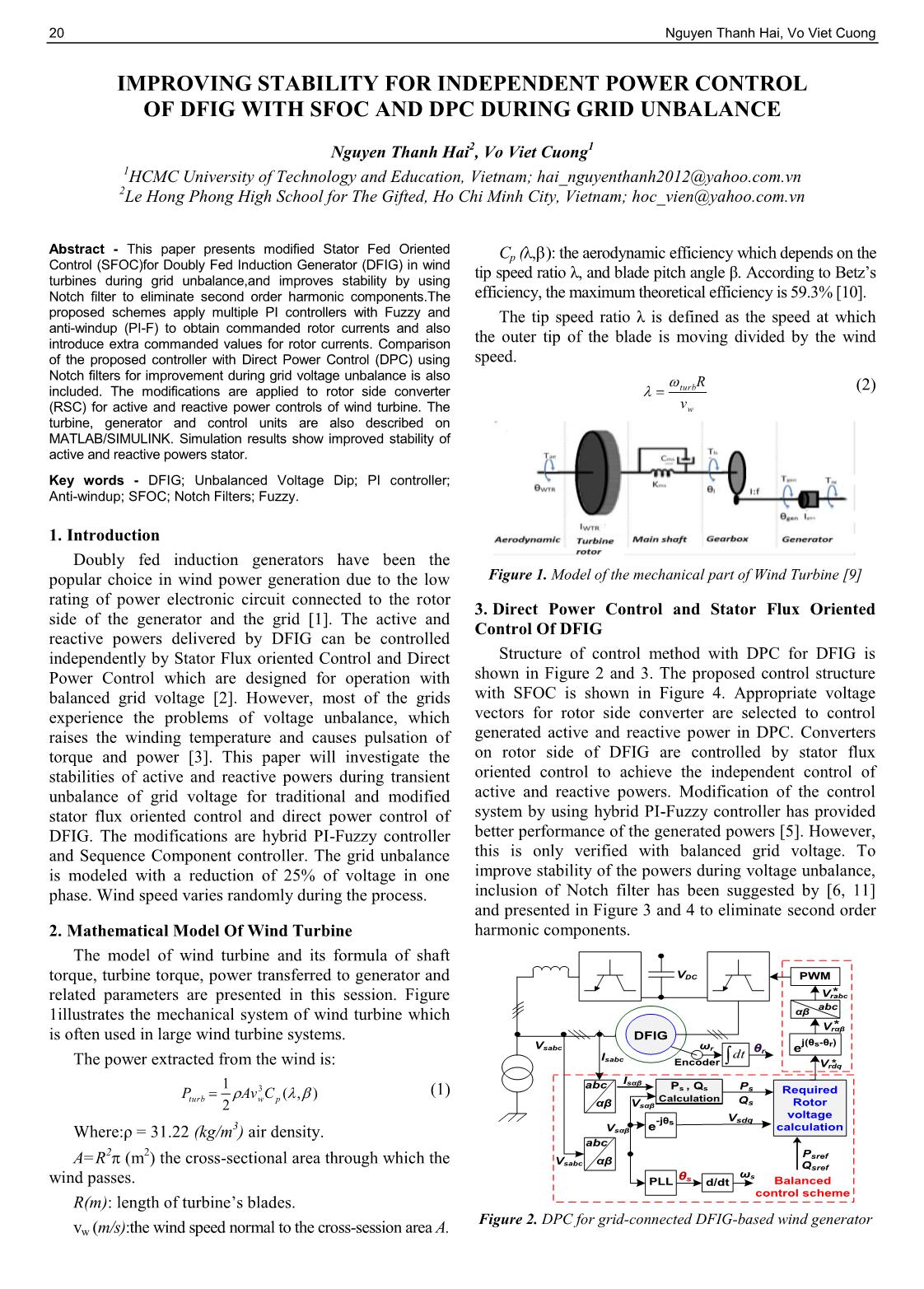
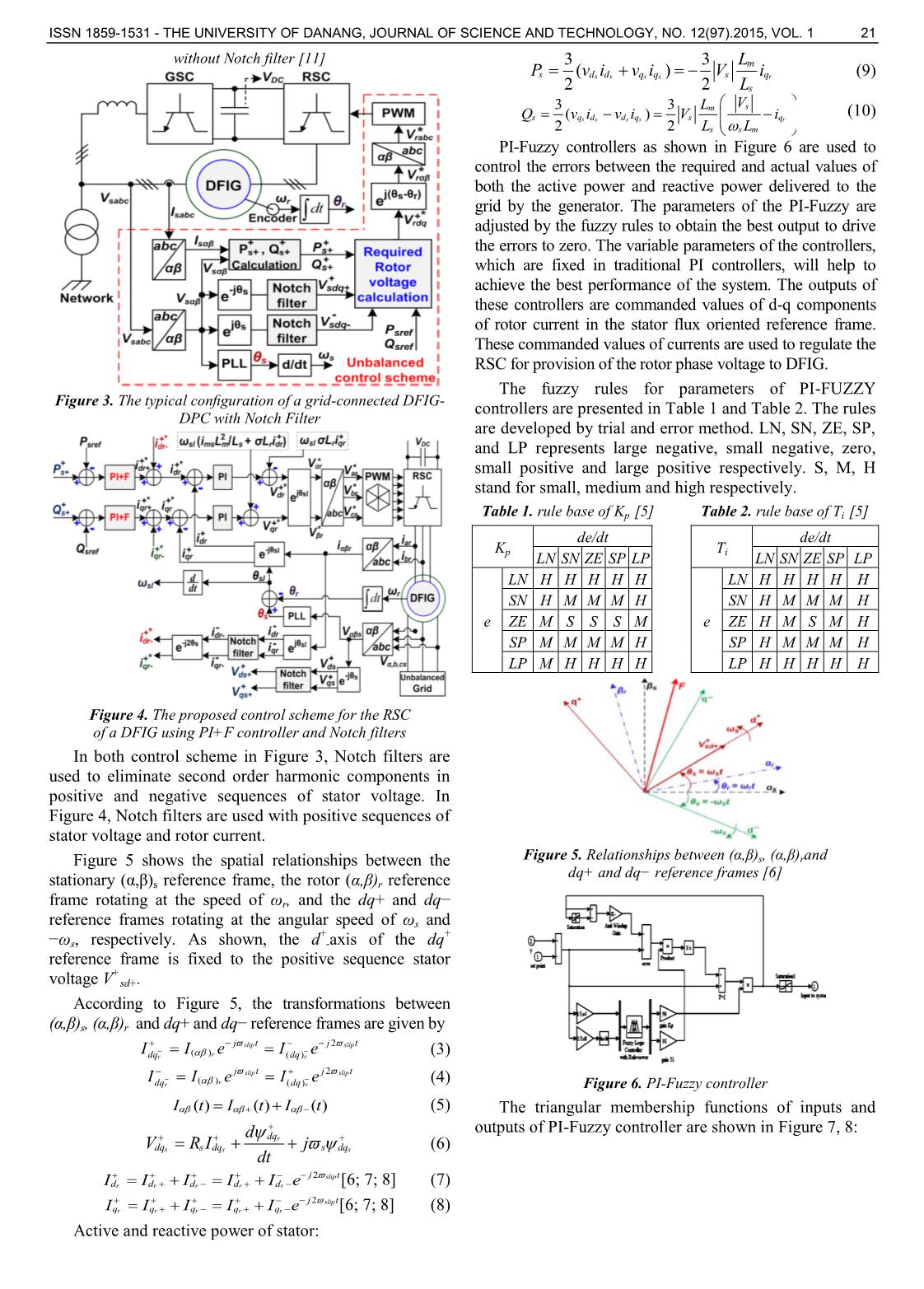
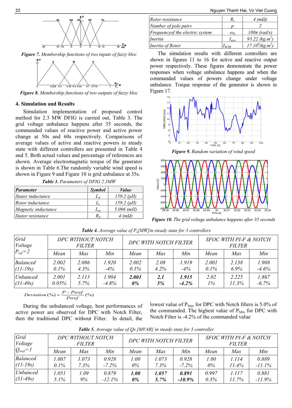
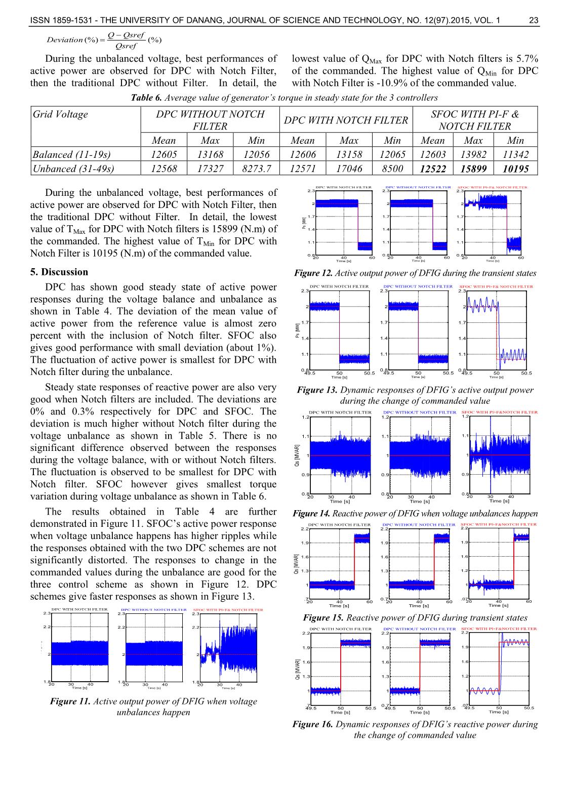
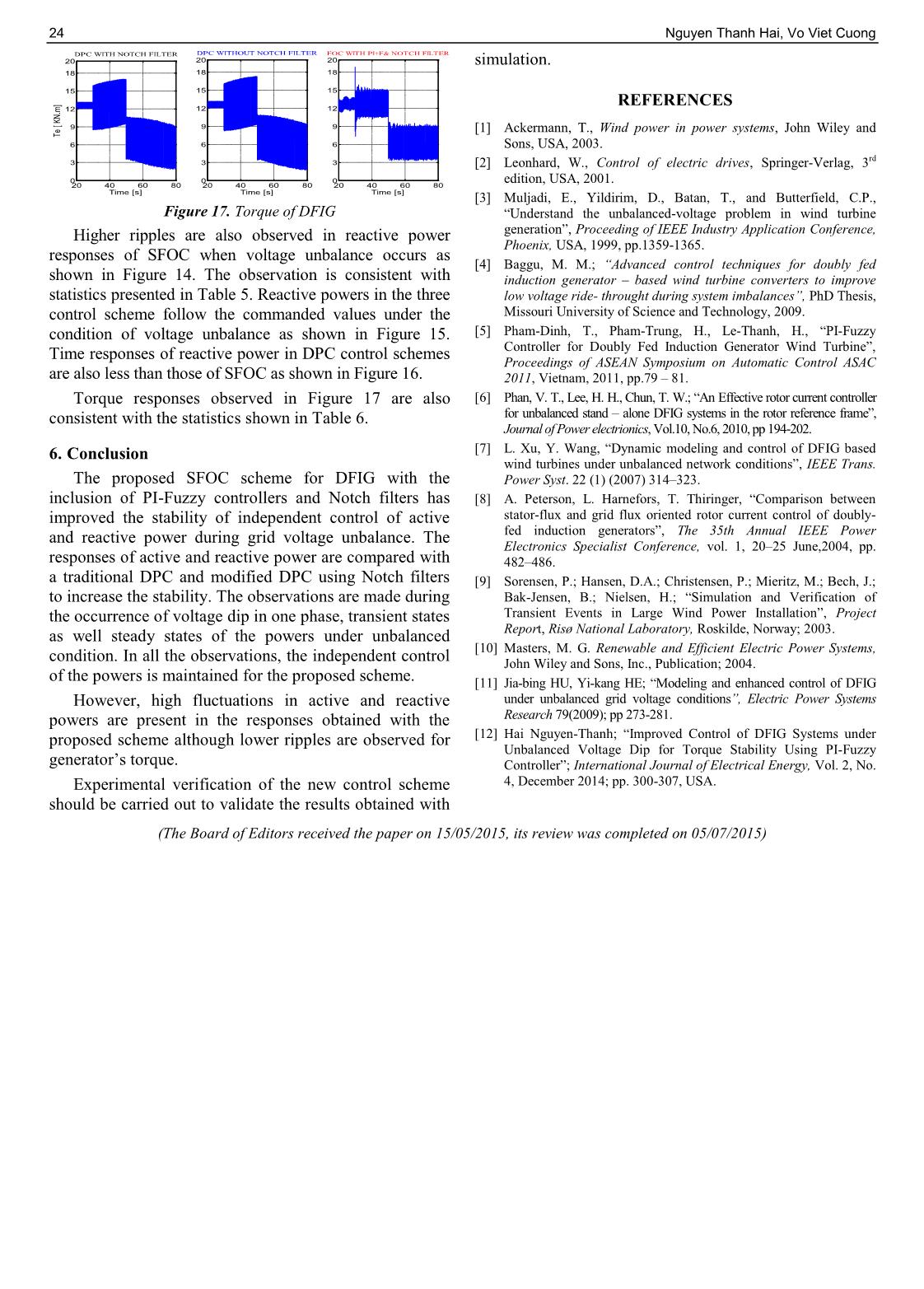
oposed control scheme for the RSC of a DFIG using PI+F controller and Notch filters In both control scheme in Figure 3, Notch filters are used to eliminate second order harmonic components in positive and negative sequences of stator voltage. In Figure 4, Notch filters are used with positive sequences of stator voltage and rotor current. Figure 5 shows the spatial relationships between the stationary (α,β)s reference frame, the rotor (α,β)r reference frame rotating at the speed of ωr, and the dq+ and dq− reference frames rotating at the angular speed of ωs and −ωs, respectively. As shown, the d + -axis of the dq + reference frame is fixed to the positive sequence stator voltage V + sd+. According to Figure 5, the transformations between (α,β)s, (α,β)r and dq+ and dq− reference frames are given by 2 ( ) ( ) slip slip rr r j t j t dq dqI I e I e (3) 2 ( ) ( ) slip slip rr r j t j t dq dqI I e I e (4) ( ) ( ) ( )I t I t I t (5) s s s s dq dq s dq s dq d V R I j dt (6) 2 slip r r r r r j t d d d d dI I I I I e [6; 7; 8] (7) 2 slipr r r r r j t q q q q qI I I I I e [6; 7; 8] (8) Active and reactive power of stator: 3 3 ( ) 2 2 s s s s r m s d d q q s q s L P v i v i V i L (9) 3 3( ) 2 2 s s s s r sm s q d d q s q s s m VL Q v i v i V i L L (10) PI-Fuzzy controllers as shown in Figure 6 are used to control the errors between the required and actual values of both the active power and reactive power delivered to the grid by the generator. The parameters of the PI-Fuzzy are adjusted by the fuzzy rules to obtain the best output to drive the errors to zero. The variable parameters of the controllers, which are fixed in traditional PI controllers, will help to achieve the best performance of the system. The outputs of these controllers are commanded values of d-q components of rotor current in the stator flux oriented reference frame. These commanded values of currents are used to regulate the RSC for provision of the rotor phase voltage to DFIG. The fuzzy rules for parameters of PI-FUZZY controllers are presented in Table 1 and Table 2. The rules are developed by trial and error method. LN, SN, ZE, SP, and LP represents large negative, small negative, zero, small positive and large positive respectively. S, M, H stand for small, medium and high respectively. Table 1. rule base of Kp [5] Table 2. rule base of Ti [5] Kp de/dt Ti de/dt LN SN ZE SP LP LN SN ZE SP LP e LN H H H H H e LN H H H H H SN H M M M H SN H M M M H ZE M S S S M ZE H M S M H SP M M M M H SP H M M M H LP M H H H H LP H H H H H Figure 5. Relationships between (α,β)s, (α,β)rand dq+ and dq− reference frames [6] Figure 6. PI-Fuzzy controller The triangular membership functions of inputs and outputs of PI-Fuzzy controller are shown in Figure 7, 8: 22 Nguyen Thanh Hai, Vo Viet Cuong Figure 7. Membership functions of two inputs of fuzzy bloc Figure 8. Membership functions of two outputs of fuzzy bloc 4. Simulation and Results Simulation implementation of proposed control method for 2.3 MW DFIG is carried out, Table 3. The grid voltage unbalance happens after 35 seconds, the commanded values of reactive power and active power change at 50s and 60s respectively. Comparisons of average values of active and reactive powers in steady state with different controllers are presented in Table 4 and 5. Both actual values and percentage of references are shown. Average electromagnetic torque of the generator is shown in Table 6.The randomly variable wind speed is shown in Figure 9 and Figure 10 is grid unbalance at 35s. Table 3. Parameters of DFIG 2.3MW Parameter Symbol Value Stator inductance LS 159.2 (μH) Rotor inductance Lr 159.2 (μH) Magnetic inductance Lm 5.096 (mH) Stator resistance RS 4 (mΩ) Rotor resistance Rr 4 (mΩ) Number of pole pairs p 2 Frequencyof the electric system ωS 100π (rad/s) Inertia Igen 93.22 (kg.m 2) Inertia of Rotor IWTR 17.10 6(kg.m2) The simulation results with different controllers are shown in figures 11 to 16 for active and reactive output power respectively. These figures demonstrate the power responses when voltage unbalance happens and when the commanded values of powers change under voltage unbalance. Torque response of the generator is shown in Figure 17. Figure 9. Random variation of wind speed Figure 10. The grid voltage unbalance happens after 35 seconds Table 4. Average value of Ps[MW]in steady state for 3 controllers Grid Voltage Psef =2 DPC WITHOUT NOTCH FILTER DPC WITH NOTCH FILTER SFOC WITH PI-F & NOTCH FILTER Mean Max Min Mean Max Min Mean Max Min Balanced (11-19s) 2.002 0.1% 2.086 4.3% 1.920 -4% 2.002 0.1% 2.08 4.2% 1.919 -4% 2.001 0.1% 2.138 6.9% 1.908 -4.6% Unbanced (31-49s) 2.001 0.05% 2.113 5.7% 1.904 -4.8% 2.001 0% 2.1 5% 1.915 -4.2% 2.02 1% 2.225 11.3% 1.867 -6.7% During the unbalanced voltage, best performances of active power are observed for DPC with Notch Filter, then the traditional DPC without Filter. In detail, the lowest value of PMax for DPC with Notch filters is 5.0% of the commanded. The highest value of PMin for DPC with Notch Filter is -4.2% of the commanded value Table 5. Average value of Qs [MVAR] in steady state for 3 controller Grid Voltage Qsref =1 DPC WITHOUT NOTCH FILTER DPC WITH NOTCH FILTER SFOC WITH PI-F & NOTCH FILTER Mean Max Min Mean Max Min Mean Max Min Balanced (11-19s) 1.007 0.1% 1.073 7.3% 0.928 -7.2% 1.00 0% 1.073 7.3% 0.928 -7.2% 1.00 0% 1.114 11.4% 0.889 -11.1% Unbanced (31-49s) 1.051 5.1% 1.09 9% 0.879 -12.1% 1.00 0% 1.057 5.7% 0.891 -10.9% 0.997 0.3% 1.117 11.7% 0.881 -11.9% 29.95 29.96 29.97 29.98 29.99 30 30.01 30.02 30.03 30.04 30.05 -800 -600 -400 -200 0 200 400 600 800 Time [s] V a b c s [ V ] %)( %)( Psref PsrefP Deviation ISSN 1859-1531 - THE UNIVERSITY OF DANANG, JOURNAL OF SCIENCE AND TECHNOLOGY, NO. 12(97).2015, VOL. 1 23 During the unbalanced voltage, best performances of active power are observed for DPC with Notch Filter, then the traditional DPC without Filter. In detail, the lowest value of QMax for DPC with Notch filters is 5.7% of the commanded. The highest value of QMin for DPC with Notch Filter is -10.9% of the commanded value. Table 6. Average value of generator’s torque in steady state for the 3 controllers Grid Voltage DPC WITHOUT NOTCH FILTER DPC WITH NOTCH FILTER SFOC WITH PI-F & NOTCH FILTER Mean Max Min Mean Max Min Mean Max Min Balanced (11-19s) 12605 13168 12056 12606 13158 12065 12603 13982 11342 Unbanced (31-49s) 12568 17327 8273.7 12571 17046 8500 12522 15899 10195 During the unbalanced voltage, best performances of active power are observed for DPC with Notch Filter, then the traditional DPC without Filter. In detail, the lowest value of TMax for DPC with Notch filters is 15899 (N.m) of the commanded. The highest value of TMin for DPC with Notch Filter is 10195 (N.m) of the commanded value. 5. Discussion DPC has shown good steady state of active power responses during the voltage balance and unbalance as shown in Table 4. The deviation of the mean value of active power from the reference value is almost zero percent with the inclusion of Notch filter. SFOC also gives good performance with small deviation (about 1%). The fluctuation of active power is smallest for DPC with Notch filter during the unbalance. Steady state responses of reactive power are also very good when Notch filters are included. The deviations are 0% and 0.3% respectively for DPC and SFOC. The deviation is much higher without Notch filter during the voltage unbalance as shown in Table 5. There is no significant difference observed between the responses during the voltage balance, with or without Notch filters. The fluctuation is observed to be smallest for DPC with Notch filter. SFOC however gives smallest torque variation during voltage unbalance as shown in Table 6. The results obtained in Table 4 are further demonstrated in Figure 11. SFOC’s active power response when voltage unbalance happens has higher ripples while the responses obtained with the two DPC schemes are not significantly distorted. The responses to change in the commanded values during the unbalance are good for the three control scheme as shown in Figure 12. DPC schemes give faster responses as shown in Figure 13. Figure 11. Active output power of DFIG when voltage unbalances happen Figure 12. Active output power of DFIG during the transient states Figure 13. Dynamic responses of DFIG’s active output power during the change of commanded value Figure 14. Reactive power of DFIG when voltage unbalances happen Figure 15. Reactive power of DFIG during transient states Figure 16. Dynamic responses of DFIG’s reactive power during the change of commanded value %)( %)( Qsref QsrefQ Deviation 20 30 40 1.8 2 2.2 2.3 DPC WITHOUT NOTCH FILTER Time [s] 20 30 40 1.8 2 2.2 2.3 SFOC WITH PI+F& NOTCH FILTER Time [s] 20 30 40 1.8 2 2.2 2.3 Time [s] P s [M W ] DPC WITH NOTCH FILTER 20 40 60 0.8 1.1 1.4 1.7 2 2.3 DPC WITHOUT NOTCH FILTER Time [s] 20 40 60 0.8 1.1 1.4 1.7 2 2.3 SFOC WITH PI+F& NOTCH FILTER Time [s] 20 40 60 0.8 1.1 1.4 1.7 2 2.3 Time [s] Ps [ M W ] DPC WITH NOTCH FILTER 49.5 50 50.5 0.8 1.1 1.4 1.7 2 2.3 DPC WITHOUT NOTCH FILTER Time [s] 49.5 50 50.5 0.8 1.1 1.4 1.7 2 2.3 SFOC WITH PI+F& NOTCH FILTER Time [s] 49.5 50 50.5 0.8 1.1 1.4 1.7 2 2.3 Time [s] P s [M W ] DPC WITH NOTCH FILTER 20 30 40 0.8 0.9 1 1.1 1.2 Time [s] Q s [M V A R ] DPC WITH NOTCH FILTER 20 30 40 0.8 0.9 1 1.1 1.2 DPC WITHOUT NOTCH FILTER Time [s] 20 30 40 0.8 0.9 1 1.1 1.2 SFOC WITH PI+F&NOTCH FILTER Time [s] 20 40 60 .7 1 1.3 1.6 1.9 2.2 Time [s] Q s [M VA R ] DPC WITH NOTCH FILTER 20 40 60 0.7 1 1.3 1.6 1.9 2.2 DPC WITHOUT NOTCH FILTER Time [s] 20 40 60 .07 1 1.2 1.6 1.9 2.2 SFOC WITH PI+F&NOTCH FILTER Time [s] 49.5 50 50.5 .7 1 1.3 1.6 1.9 2.2 Time [s] Q s [M V A R ] DPC WITH NOTCH FILTER 49.5 50 50.5 0.7 1 1.3 1.6 1.9 2.2 DPC WITHOUT NOTCH FILTER Time [s] 49.5 50 50.5 .07 1 1.2 1.6 1.9 2.2 SFOC WITH PI+F&NOTCH FILTER Time [s] 24 Nguyen Thanh Hai, Vo Viet Cuong Figure 17. Torque of DFIG Higher ripples are also observed in reactive power responses of SFOC when voltage unbalance occurs as shown in Figure 14. The observation is consistent with statistics presented in Table 5. Reactive powers in the three control scheme follow the commanded values under the condition of voltage unbalance as shown in Figure 15. Time responses of reactive power in DPC control schemes are also less than those of SFOC as shown in Figure 16. Torque responses observed in Figure 17 are also consistent with the statistics shown in Table 6. 6. Conclusion The proposed SFOC scheme for DFIG with the inclusion of PI-Fuzzy controllers and Notch filters has improved the stability of independent control of active and reactive power during grid voltage unbalance. The responses of active and reactive power are compared with a traditional DPC and modified DPC using Notch filters to increase the stability. The observations are made during the occurrence of voltage dip in one phase, transient states as well steady states of the powers under unbalanced condition. In all the observations, the independent control of the powers is maintained for the proposed scheme. However, high fluctuations in active and reactive powers are present in the responses obtained with the proposed scheme although lower ripples are observed for generator’s torque. Experimental verification of the new control scheme should be carried out to validate the results obtained with simulation. REFERENCES [1] Ackermann, T., Wind power in power systems, John Wiley and Sons, USA, 2003. [2] Leonhard, W., Control of electric drives, Springer-Verlag, 3rd edition, USA, 2001. [3] Muljadi, E., Yildirim, D., Batan, T., and Butterfield, C.P., “Understand the unbalanced-voltage problem in wind turbine generation”, Proceeding of IEEE Industry Application Conference, Phoenix, USA, 1999, pp.1359-1365. [4] Baggu, M. M.; “Advanced control techniques for doubly fed induction generator – based wind turbine converters to improve low voltage ride- throught during system imbalances”, PhD Thesis, Missouri University of Science and Technology, 2009. [5] Pham-Dinh, T., Pham-Trung, H., Le-Thanh, H., “PI-Fuzzy Controller for Doubly Fed Induction Generator Wind Turbine”, Proceedings of ASEAN Symposium on Automatic Control ASAC 2011, Vietnam, 2011, pp.79 – 81. [6] Phan, V. T., Lee, H. H., Chun, T. W.; “An Effective rotor current controller for unbalanced stand – alone DFIG systems in the rotor reference frame”, Journal of Power electrionics, Vol.10, No.6, 2010, pp 194-202. [7] L. Xu, Y. Wang, “Dynamic modeling and control of DFIG based wind turbines under unbalanced network conditions”, IEEE Trans. Power Syst. 22 (1) (2007) 314–323. [8] A. Peterson, L. Harnefors, T. Thiringer, “Comparison between stator-flux and grid flux oriented rotor current control of doubly- fed induction generators”, The 35th Annual IEEE Power Electronics Specialist Conference, vol. 1, 20–25 June,2004, pp. 482–486. [9] Sorensen, P.; Hansen, D.A.; Christensen, P.; Mieritz, M.; Bech, J.; Bak-Jensen, B.; Nielsen, H.; “Simulation and Verification of Transient Events in Large Wind Power Installation”, Project Report, Risø National Laboratory, Roskilde, Norway; 2003. [10] Masters, M. G. Renewable and Efficient Electric Power Systems, John Wiley and Sons, Inc., Publication; 2004. [11] Jia-bing HU, Yi-kang HE; “Modeling and enhanced control of DFIG under unbalanced grid voltage conditions”, Electric Power Systems Research 79(2009); pp 273-281. [12] Hai Nguyen-Thanh; “Improved Control of DFIG Systems under Unbalanced Voltage Dip for Torque Stability Using PI-Fuzzy Controller”; International Journal of Electrical Energy, Vol. 2, No. 4, December 2014; pp. 300-307, USA. (The Board of Editors received the paper on 15/05/2015, its review was completed on 05/07/2015) 20 40 60 80 0 3 6 9 12 15 18 20 Time [s] Te [ K N .m ] DPC WITH NOTCH FILTER 20 40 60 80 0 3 6 9 12 15 18 20 DPC WITHOUT NOTCH FILTER Time [s] 20 40 60 80 0 3 6 9 12 15 18 20 FOC WITH PI+F& NOTCH FILTER Time [s]
File đính kèm:
 improving_stability_for_independent_power_control_of_dfig_wi.pdf

