Hybrid active power filter method in frequency domain for quality improvement in variable frequency drive applications
We present in this paper a control method of a novel hybrid parallel active
power filter (HPAPF) used for harmonic currents elimination and reactive power
compensation in the power system for threephase variable frequency drives (VFDs).
The HPAPF configuration is built from two basically filter components including
harmonics tuned passive filter and active power electronics filter. The active power
electronics filter of this proposed HPAPF system is controlled with a new control
algorithm that makes use of Fourier analysis to facilitate accurate selective harmonics
targeting allowing cooperation between passive and active components. As such a
coupling of the passive filter component and the active filter component allows to
reduce significantly the current rating of the active filter component. This reduction in
current rating implies a great economic advantage of the proposed HPAPF compared
to the method which bases only on the pure active power electronics filter. The
hardware design and the control algorithm of the proposed HPAPF are verified by
MATLAB/Simulink software.
Trang 1
Trang 2
Trang 3
Trang 4
Trang 5
Trang 6
Trang 7
Trang 8
Trang 9
Trang 10
Tải về để xem bản đầy đủ
Tóm tắt nội dung tài liệu: Hybrid active power filter method in frequency domain for quality improvement in variable frequency drive applications
e phase power networks is proposed
and studied. The strategy is a parallel configuration of low order passive harmonics
filter and selective shunt active power filter. Frequency domain Fourier Transform
analysis and robust PI controllers are used to design control algorithm. PHPF
performance is verified by modeling and using Matlab/Simulink software for the
simulations.
2. CONSTRUCTION OF PROPOSED HPAPF
2.1. Design of Passive Components
Single tuned topology is chosen to implement the passive component because it is
simple to construct and economically viable. Along with high pass and double tuned
filters, single tuned passive filter is one of the most commonly used type of harmonics
filter in three phase systems.
PHÂN BAN PHÂN PHỐI ĐIỆN | 567
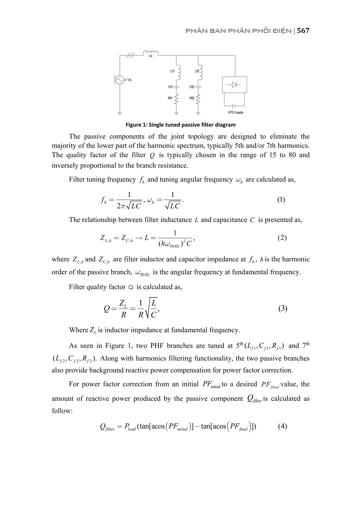
Figure 1: Single tuned passive filter diagram
The passive components of the joint topology are designed to eliminate the
majority of the lower part of the harmonic spectrum, typically 5th and/or 7th harmonics.
The quality factor of the filter Q is typically chosen in the range of 15 to 80 and
inversely proportional to the branch resistance.
Filter tuning frequency hf and tuning angular frequency hw are calculated as,
1 1, . (1)
2h h
f
LC LC
wp= =
The relationship between filter inductance L and capacitance C is presented as,
 , , 2
50
1 , (2)
( )L h C h Hz
Z Z L
h Cw= =
where ,L hZ and C,hZ are filter inductor and capacitor impedance at hf , h is the harmonic
order of the passive branch, 50Hzw is the angular frequency at fundamental frequency.
Filter quality factor Q is calculated as,
1 , (3)L LQ
R R C
Z= =
Where LZ is inductor impedance at fundamental frequency.
As seen in Figure 1, two PHF branches are tuned at 5th 1 1 1( , , )f f fL C R and 7th
2 2 2( , , ).f f fL C R Along with harmonics filtering functionality, the two passive branches
also provide background reactive power compensation for power factor correction.
For power factor correction from an initial initialPF to a desired finalPF value, the
amount of reactive power produced by the passive component filterQ is calculated as
follow:
 ( ) ( )(tan[acos ] tan[acos ]) (4)inifilter lo tiad finalalQ P PF PF= -
568 | HỘI NGHỊ KHOA HỌC VÀ CÔNG NGHỆ ĐIỆN LỰC TOÀN QUỐC 2017
filterQ can also be calculated as,
2
2 . (5)
1
filter C L C
hQ Q Q Q
h
-= - =
When CQ is obtained,C and Lcan be found as describe in [6]. Finally, R can be
calculated via selection of quality factor.
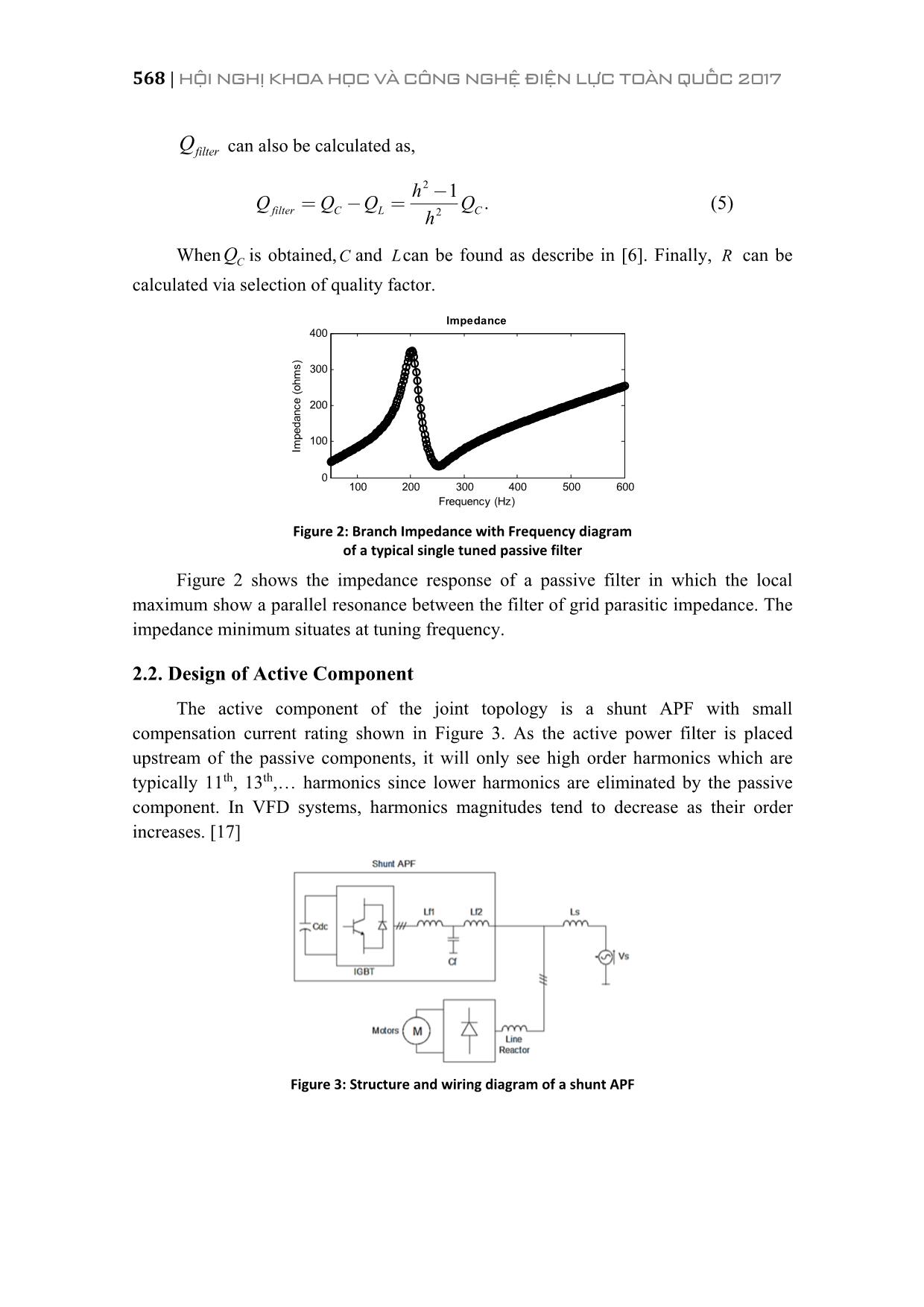
Figure 2: Branch Impedance with Frequency diagram
of a typical single tuned passive filter
Figure 2 shows the impedance response of a passive filter in which the local
maximum show a parallel resonance between the filter of grid parasitic impedance. The
impedance minimum situates at tuning frequency.
2.2. Design of Active Component
The active component of the joint topology is a shunt APF with small
compensation current rating shown in Figure 3. As the active power filter is placed
upstream of the passive components, it will only see high order harmonics which are
typically 11th, 13th, harmonics since lower harmonics are eliminated by the passive
component. In VFD systems, harmonics magnitudes tend to decrease as their order
increases. [17]
Figure 3: Structure and wiring diagram of a shunt APF
100 200 300 400 500 600
0
100
200
300
400
Impedance
Im
pe
da
nc
e
(o
hm
s)
Frequency (Hz)
PHÂN BAN PHÂN PHỐI ĐIỆN | 569
In principle, the active filter stores electrical energy in its DC bus, which is a high
voltage DC capacitor, and convert this DC voltage into three phase AC voltage and
current. The control algorithm decides how much reactive power is being supplied to
the grid by varying the output current phase and amplitude. This can be achieved to
estimating the correct amount of reactive power needed by the non linear load using
voltage and current feedback signals measured at the point of common coupling (PCC)
and DC bus. Details about the control algorithm will be discussed further in the next
section.
3. CONTROL METHODOLOGY
3.1. Frequency Domain Analysis of Harmonics Current
Fourier Transform is used to analyse load feedback signal to provide flexible
selective harmonic current generation.
Discrete Fourier Transform (DFT) is the digital form of Fourier Transform. DFT
of a discrete signal sampled N times in a cycle is defined:
21
1
0
 (. 6)
j kN
n
k
k
X x e
p-
=
=å
Inverse DFT of 1X is defined as:
2
1 1
1 (7).
j k
N
kx X eN
p-=
This allows the selection of high order harmonics while omitting lower
components. According to Fourier Transform, load current can be represented as:
( ) ( )1 ,
2
( ), (8)load load load n
n
i t i t i t
¥
=
= +å
where, 1( )load ti represents the fundamental component and , ( )load ni t is the function of
harmonic components.
3.2. APF Reference Current Calculation and Control Loops For PWM
Generation
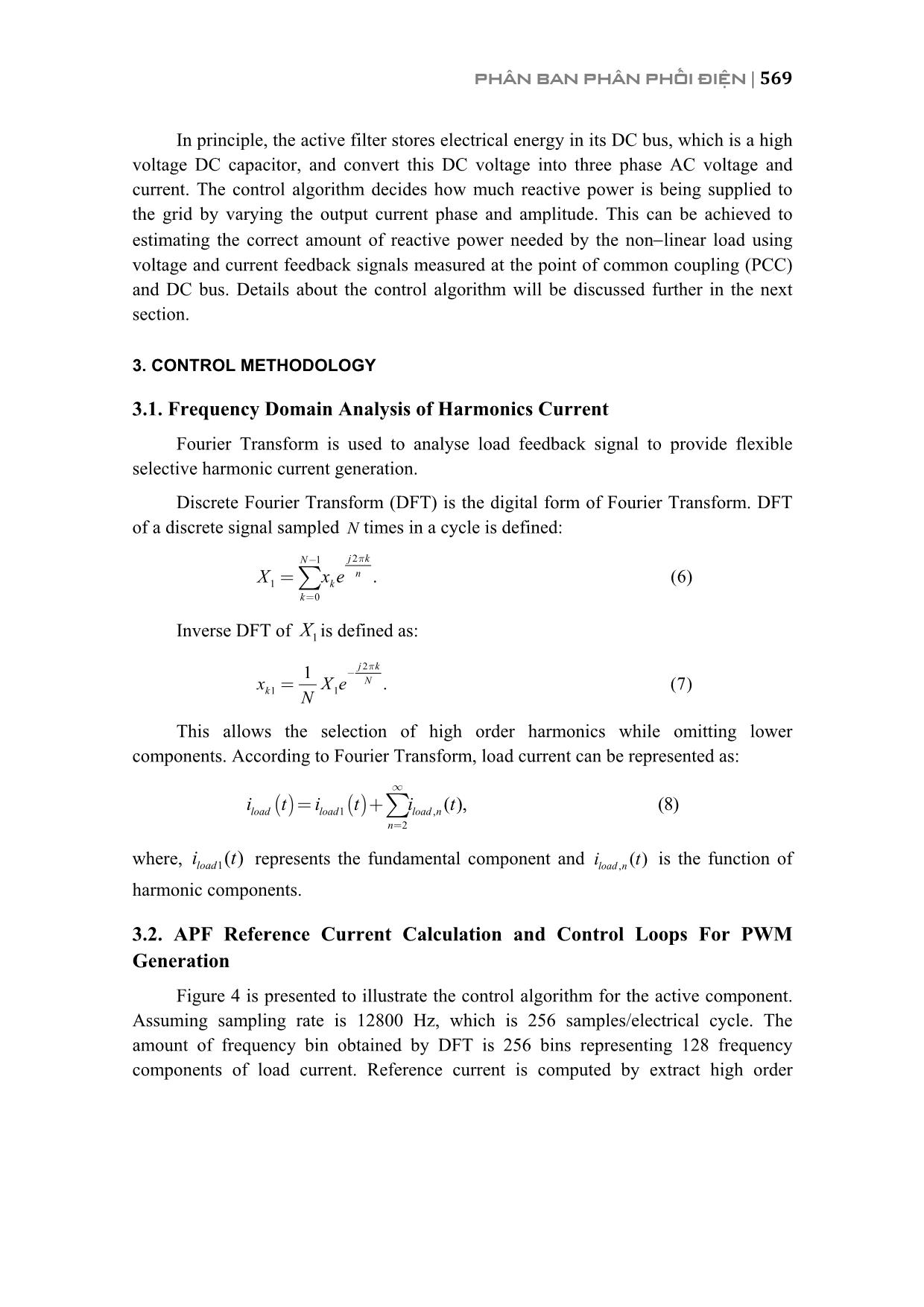
Figure 4 is presented to illustrate the control algorithm for the active component.
Assuming sampling rate is 12800 Hz, which is 256 samples/electrical cycle. The
amount of frequency bin obtained by DFT is 256 bins representing 128 frequency
components of load current. Reference current is computed by extract high order
570 | HỘI NGHỊ KHOA HỌC VÀ CÔNG NGHỆ ĐIỆN LỰC TOÀN QUỐC 2017
harmonics from DFT analysis of load feedback current, namely 11th to 128th frequency
bins, and then takes the inverse DFT of this frequency range.
Figure 4: Control algorithm for the active component
A control loop also includes a DC bus voltage regulator in order to keep DC bus
stable at a reference value. Output of the DC bus PI controller is then added to
harmonics reference current along with reactive power compensation reference current.
Another PI controller is used to generate pulse width modulation signals and regulate
APF output compensation current. The PWM generation module is a Sinusoidal PWM
which creates PWM pulses a specific switching frequency, normally from 8 kHz to 15
kHz.
4. SIMULATION RESULTS
4.1. Case Study of a VFD System
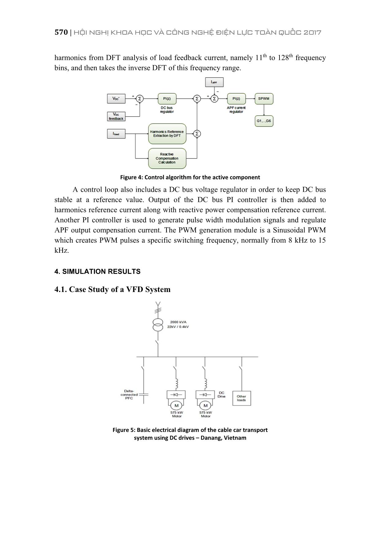
Figure 5: Basic electrical diagram of the cable car transport
system using DC drives – Danang, Vietnam
PHÂN BAN PHÂN PHỐI ĐIỆN | 571
For the purpose of demonstrating the performance of the joint topology, a case
study shown in Figure 5 at a cable car transport system in Danang, Vietnam is
conducted. Power quality parameters are obtained by an Elspec G4500 Blackbox
industrial monitor. In this case, the harmonics pollution exemplifies the harmonics
generating characteristic of DC drives in industrial application. The electrical system at
Station 6 consists of a pair of 575 kW DC motors driven by 2 ABB DCS800 DC drives,
supplied by a 2 MVA 22 kV/0.4kV Delta/Wye Transformer.
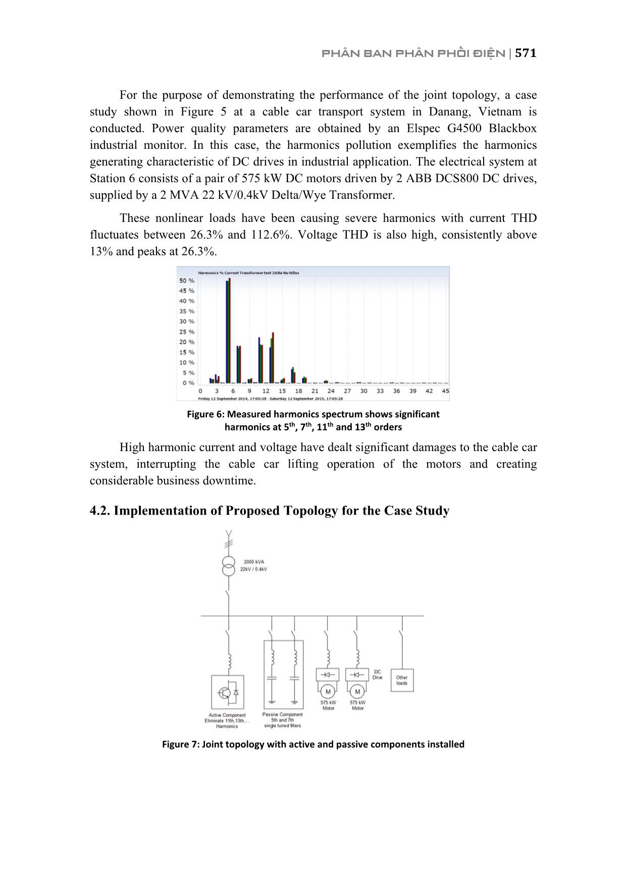
These nonlinear loads have been causing severe harmonics with current THD
fluctuates between 26.3% and 112.6%. Voltage THD is also high, consistently above
13% and peaks at 26.3%.
Figure 6: Measured harmonics spectrum shows significant
harmonics at 5th, 7th, 11th and 13th orders
High harmonic current and voltage have dealt significant damages to the cable car
system, interrupting the cable car lifting operation of the motors and creating
considerable business downtime.
4.2. Implementation of Proposed Topology for the Case Study
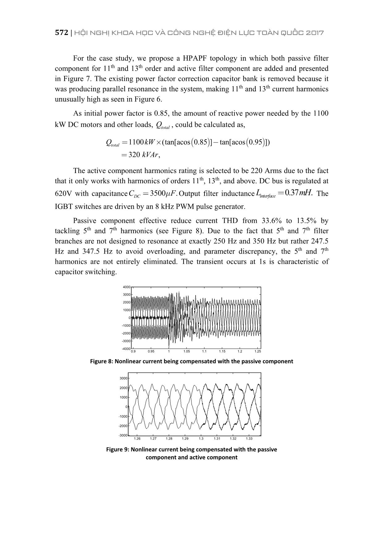
Figure 7: Joint topology with active and passive components installed
572 | HỘI NGHỊ KHOA HỌC VÀ CÔNG NGHỆ ĐIỆN LỰC TOÀN QUỐC 2017
For the case study, we propose a HPAPF topology in which both passive filter
component for 11th and 13th order and active filter component are added and presented
in Figure 7. The existing power factor correction capacitor bank is removed because it
was producing parallel resonance in the system, making 11th and 13th current harmonics
unusually high as seen in Figure 6.
As initial power factor is 0.85, the amount of reactive power needed by the 1100
kW DC motors and other loads, totalQ , could be calculated as,
( ) ( )1100 (tan[acos 0.85 ] tan[acos 0.95 ])
320 ,
totalQ kW
kVAr
= ´ -
=
The active component harmonics rating is selected to be 220 Arms due to the fact
that it only works with harmonics of orders 11th, 13th, and above. DC bus is regulated at
620V with capacitance 3500 .DCC Fm= Output filter inductance 0.37 .interfaceL mH= The
IGBT switches are driven by an 8 kHz PWM pulse generator.
Passive component effective reduce current THD from 33.6% to 13.5% by
tackling 5th and 7th harmonics (see Figure 8). Due to the fact that 5th and 7th filter
branches are not designed to resonance at exactly 250 Hz and 350 Hz but rather 247.5
Hz and 347.5 Hz to avoid overloading, and parameter discrepancy, the 5th and 7th
harmonics are not entirely eliminated. The transient occurs at 1s is characteristic of
capacitor switching.
Figure 8: Nonlinear current being compensated with the passive component
Figure 9: Nonlinear current being compensated with the passive
component and active component
0.9 0.95 1 1.05 1.1 1.15 1.2 1.25
-4000
-3000
-2000
-1000
0
1000
2000
3000
4000
1.26 1.27 1.28 1.29 1.3 1.31 1.32 1.33
-3000
-2000
-1000
0
1000
2000
3000
PHÂN BAN PHÂN PHỐI ĐIỆN | 573
In Figure 9, the active component is switched on at 1.3s after the passive
component is stable. High frequency fluctuation is considerable reduced since 11th and
13th are eliminated. Current THD is further decreased to 10.1%.
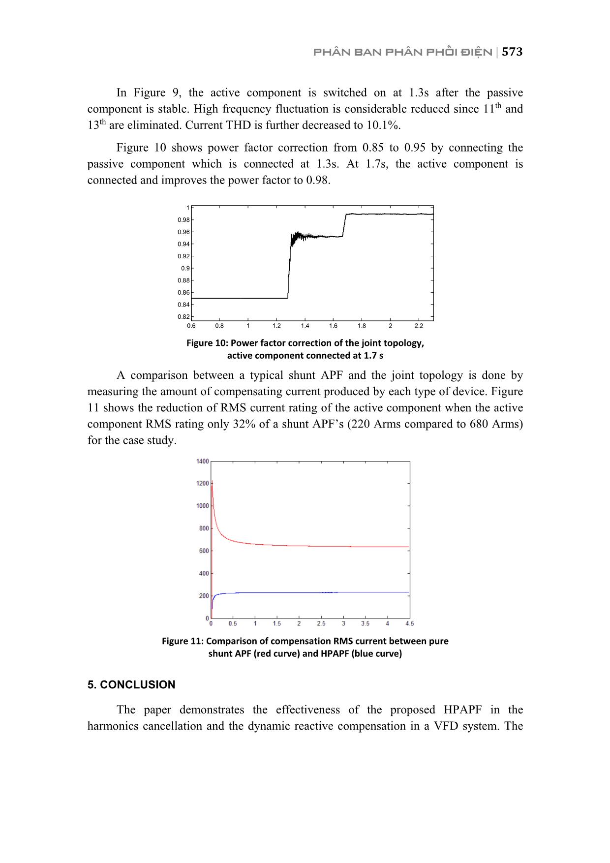
Figure 10 shows power factor correction from 0.85 to 0.95 by connecting the
passive component which is connected at 1.3s. At 1.7s, the active component is
connected and improves the power factor to 0.98.
Figure 10: Power factor correction of the joint topology,
active component connected at 1.7 s
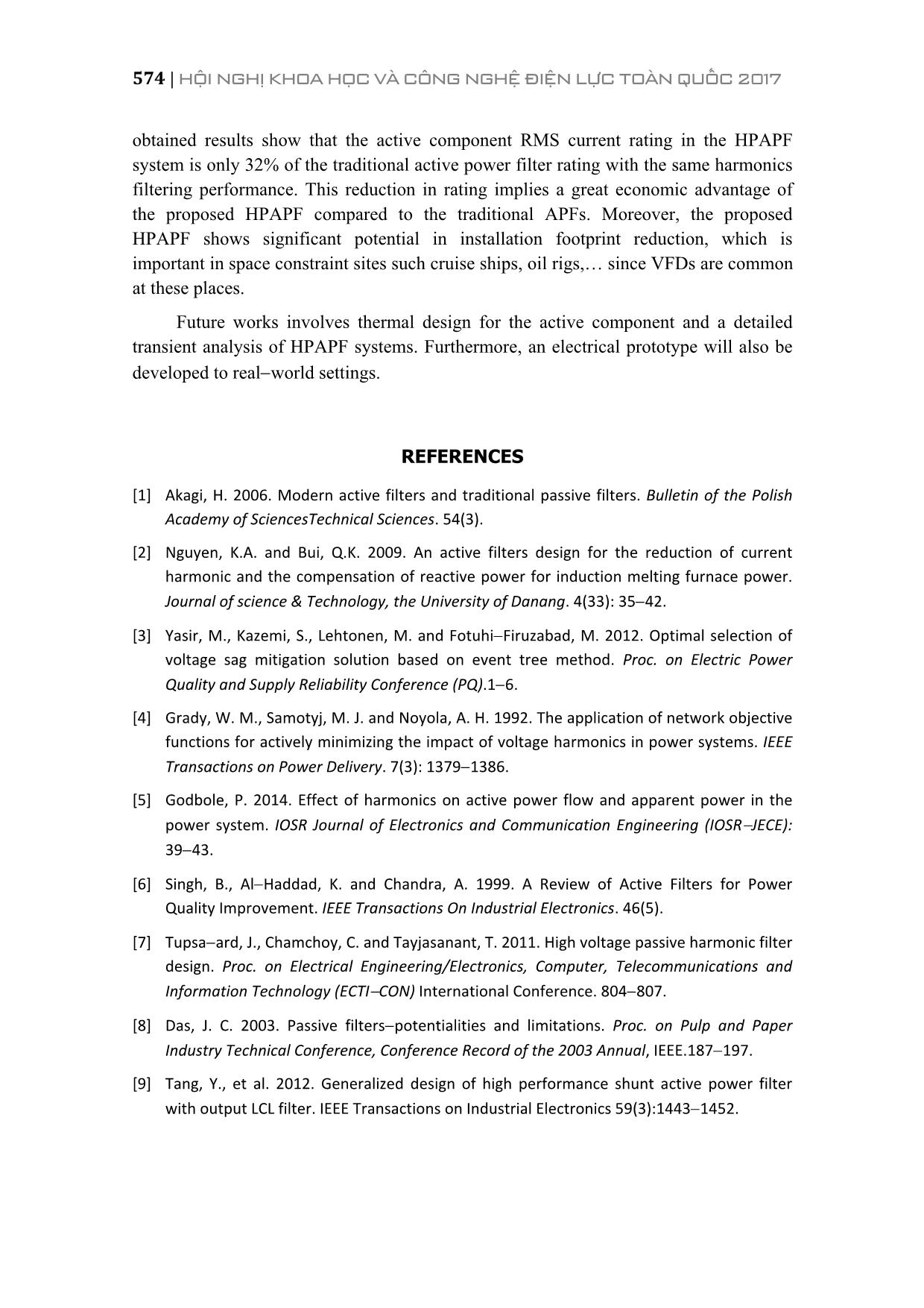
A comparison between a typical shunt APF and the joint topology is done by
measuring the amount of compensating current produced by each type of device. Figure
11 shows the reduction of RMS current rating of the active component when the active
component RMS rating only 32% of a shunt APF’s (220 Arms compared to 680 Arms)
for the case study.
Figure 11: Comparison of compensation RMS current between pure
shunt APF (red curve) and HPAPF (blue curve)
5. CONCLUSION
The paper demonstrates the effectiveness of the proposed HPAPF in the
harmonics cancellation and the dynamic reactive compensation in a VFD system. The
0.6 0.8 1 1.2 1.4 1.6 1.8 2 2.2
0.82
0.84
0.86
0.88
0.9
0.92
0.94
0.96
0.98
1
574 | HỘI NGHỊ KHOA HỌC VÀ CÔNG NGHỆ ĐIỆN LỰC TOÀN QUỐC 2017
obtained results show that the active component RMS current rating in the HPAPF
system is only 32% of the traditional active power filter rating with the same harmonics
filtering performance. This reduction in rating implies a great economic advantage of
the proposed HPAPF compared to the traditional APFs. Moreover, the proposed
HPAPF shows significant potential in installation footprint reduction, which is
important in space constraint sites such cruise ships, oil rigs, since VFDs are common
at these places.
Future works involves thermal design for the active component and a detailed
transient analysis of HPAPF systems. Furthermore, an electrical prototype will also be
developed to real world settings.
REFERENCES
[1] Akagi, H. 2006. Modern active filters and traditional passive filters. Bulletin of the Polish
Academy of SciencesTechnical Sciences. 54(3).
[2] Nguyen, K.A. and Bui, Q.K. 2009. An active filters design for the reduction of current
harmonic and the compensation of reactive power for induction melting furnace power.
Journal of science & Technology, the University of Danang. 4(33): 35 42.
[3] Yasir, M., Kazemi, S., Lehtonen, M. and Fotuhi Firuzabad, M. 2012. Optimal selection of
voltage sag mitigation solution based on event tree method. Proc. on Electric Power
Quality and Supply Reliability Conference (PQ).1 6.
[4] Grady, W. M., Samotyj, M. J. and Noyola, A. H. 1992. The application of network objective
functions for actively minimizing the impact of voltage harmonics in power systems. IEEE
Transactions on Power Delivery. 7(3): 1379 1386.
[5] Godbole, P. 2014. Effect of harmonics on active power flow and apparent power in the
power system. IOSR Journal of Electronics and Communication Engineering (IOSR JECE):
39 43.
[6] Singh, B., Al Haddad, K. and Chandra, A. 1999. A Review of Active Filters for Power
Quality Improvement. IEEE Transactions On Industrial Electronics. 46(5).
[7] Tupsa ard, J., Chamchoy, C. and Tayjasanant, T. 2011. High voltage passive harmonic filter
design. Proc. on Electrical Engineering/Electronics, Computer, Telecommunications and
Information Technology (ECTI CON) International Conference. 804 807.
[8] Das, J. C. 2003. Passive filters potentialities and limitations. Proc. on Pulp and Paper
Industry Technical Conference, Conference Record of the 2003 Annual, IEEE.187 197.
[9] Tang, Y., et al. 2012. Generalized design of high performance shunt active power filter
with output LCL filter. IEEE Transactions on Industrial Electronics 59(3):1443 1452.
PHÂN BAN PHÂN PHỐI ĐIỆN | 575
[10] Akagi, H., Akira N. and Satoshi A. 1986. Control strategy of active power filters using
multiple voltage source PWM converters. IEEE Transactions on Industry Applications.
3:460 465.
[11] Bhavaraju, V. B. and Prasad, N. E. 1993. Analysis and design of an active power filter for
balancing unbalanced loads. IEEE Transactions on Power Electronics. 8(4): 640 647.
[12] Demirdelen, T., et al. 2013. Review of hybrid active power filter topologies and
controllers. Proc. of Fourth International Conference on Power Engineering, Energy and
Electrical Drives (POWERENG), IEEE.
[13] Kim, S. and Prasad N. E. 2002. A new hybrid active power filter (APF) topology. IEEE
Transactions on Power Electronics. 17(1): 48 54.
[14] Luo, A. et al. 2009. Development of hybrid active power filter based on the adaptive fuzzy
dividing frequency control method. IEEE Transactions on Power Delivery. 24(1): 424 432.
[15] Tzung Lin, L., Yen Ching, W., Jian Cheng, L. and Guerrero, J.M. 2015. Hybrid Active Filter
With Variable Conductance for Harmonic Resonance Suppression in Industrial Power
Systems. IEEE Transactions on Industrial Electronics. 62(2):746 756.
[16] Susila, D.J. and Rajathy, R. 2013. Power Quality Enhancement Using Hybrid Active Filter.
International Journal of Engineering Science and Innovative Technology (IJESIT). 2(3).
[17] Asadi, M. and Jalilian, A.R. 2012. A Hybrid Active Power Filter Comprising an Active
Electromagnetic Filter. PRZEGLĄD ELEKTROTECHNICZNY (Electrical Review), ISSN
0033 2097. R. 88 NR 10a.
[18] Peeran, S.M., and Creg, W.P.C 1995. Application, design, and specification of harmonic
filters for variable frequency drives. IEEE Transactions on Industry Applications. 31(4):
841 847.
File đính kèm:
 hybrid_active_power_filter_method_in_frequency_domain_for_qu.pdf

