Finite element modelling for electric field distribution around positive streamers in oil
Electric field distribution of positive streamers during propagation was determined
with the finite element method by using COMSOL multiphysics. Modelling was performed at
210 kV and 270 kV. The geometrical shape of streamers was modelled with cylinder and sphere
for the case of 210 kV while a growing cylinder was used for streamer propagation at 270 kV. In
addition, a spherical model was used for determining the relationship between the branching of
streamers and the electric field at the tip of branches. It is obtained from the simulation results
that the 2nd mode streamers has the electric field at channel tips of about 0.1 MV/cm while 8.3
MV/cm was received for the 4th mode streamers. The simulation results also reveal that the
shielding effect resulting from streamer branching significantly reduces the electric field at the
channel tips, and the shielding effect disappears with the angle between channels is about 30o-
60o depending on the size of streamer envelope. The hypothesis on correlation among velocity,
streamer branching and electric field is suggested.
Trang 1
Trang 2
Trang 3
Trang 4
Trang 5
Trang 6
Trang 7
Trang 8
Trang 9
Trang 10
Tải về để xem bản đầy đủ
Tóm tắt nội dung tài liệu: Finite element modelling for electric field distribution around positive streamers in oil
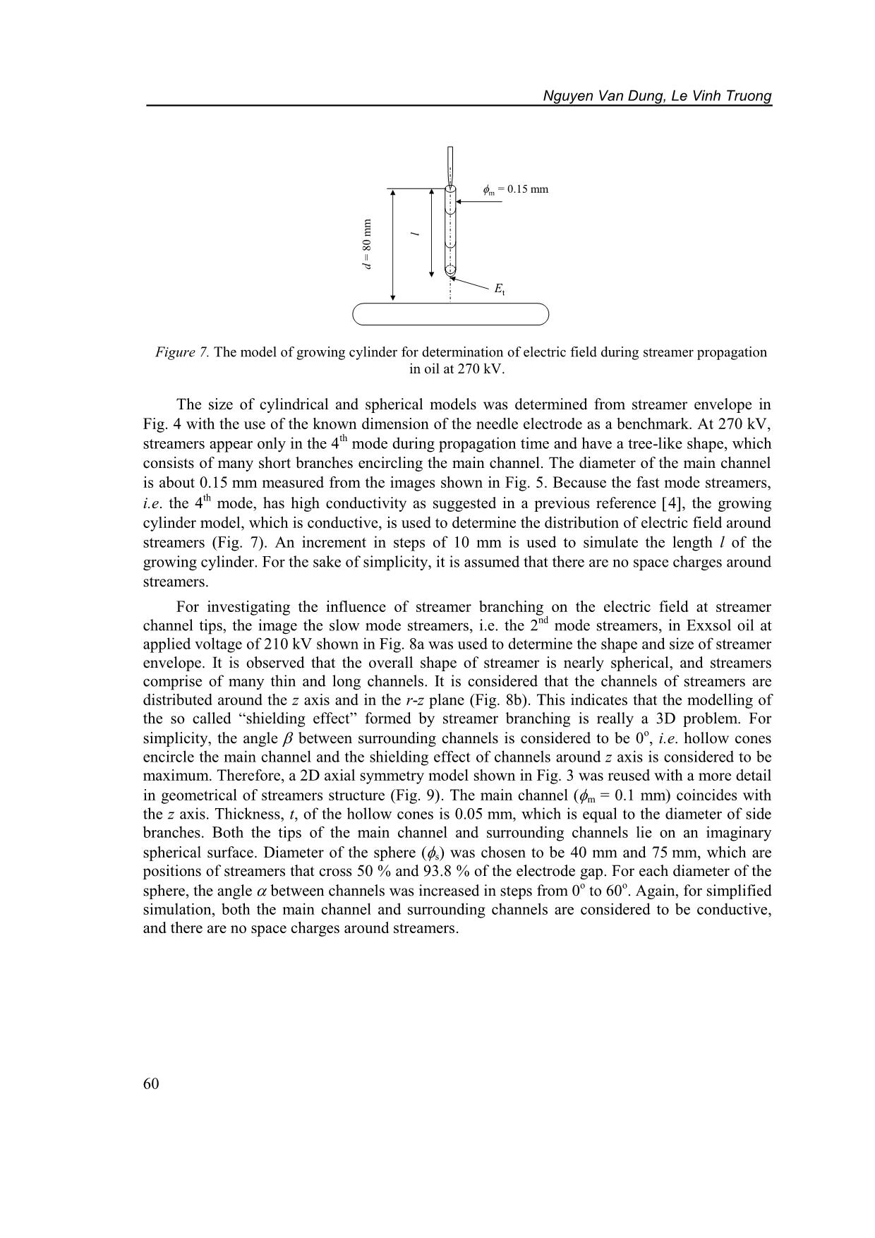
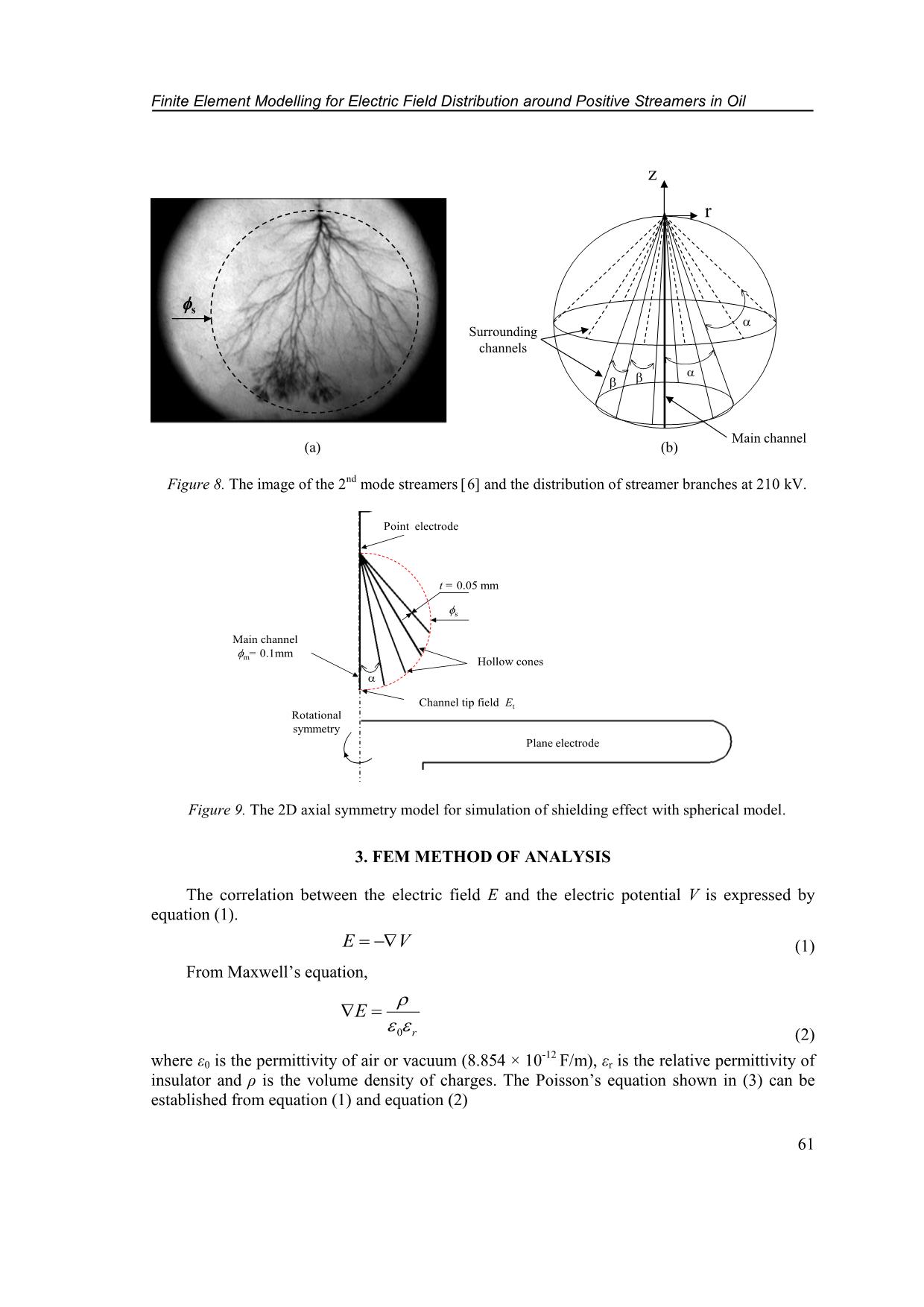
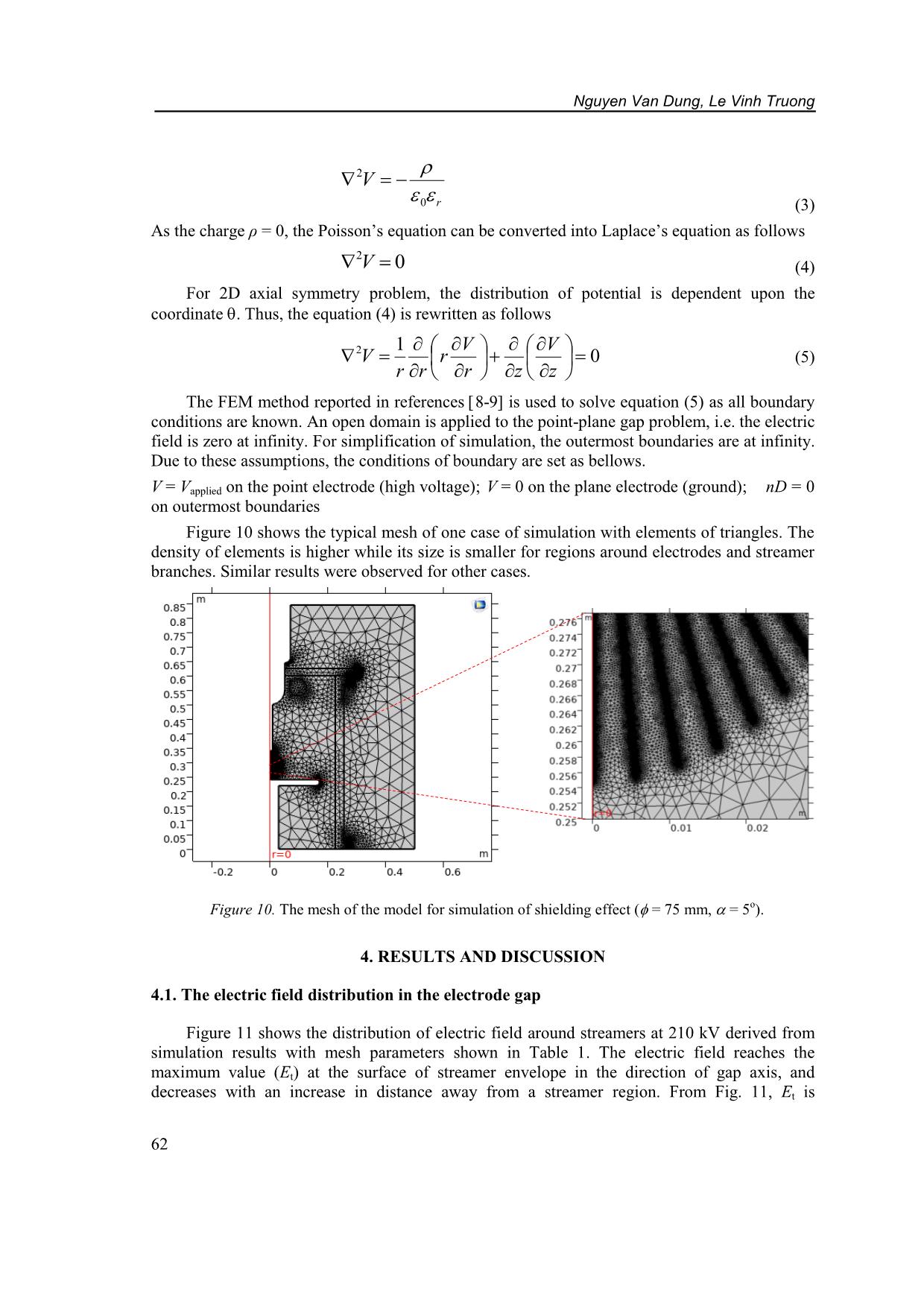
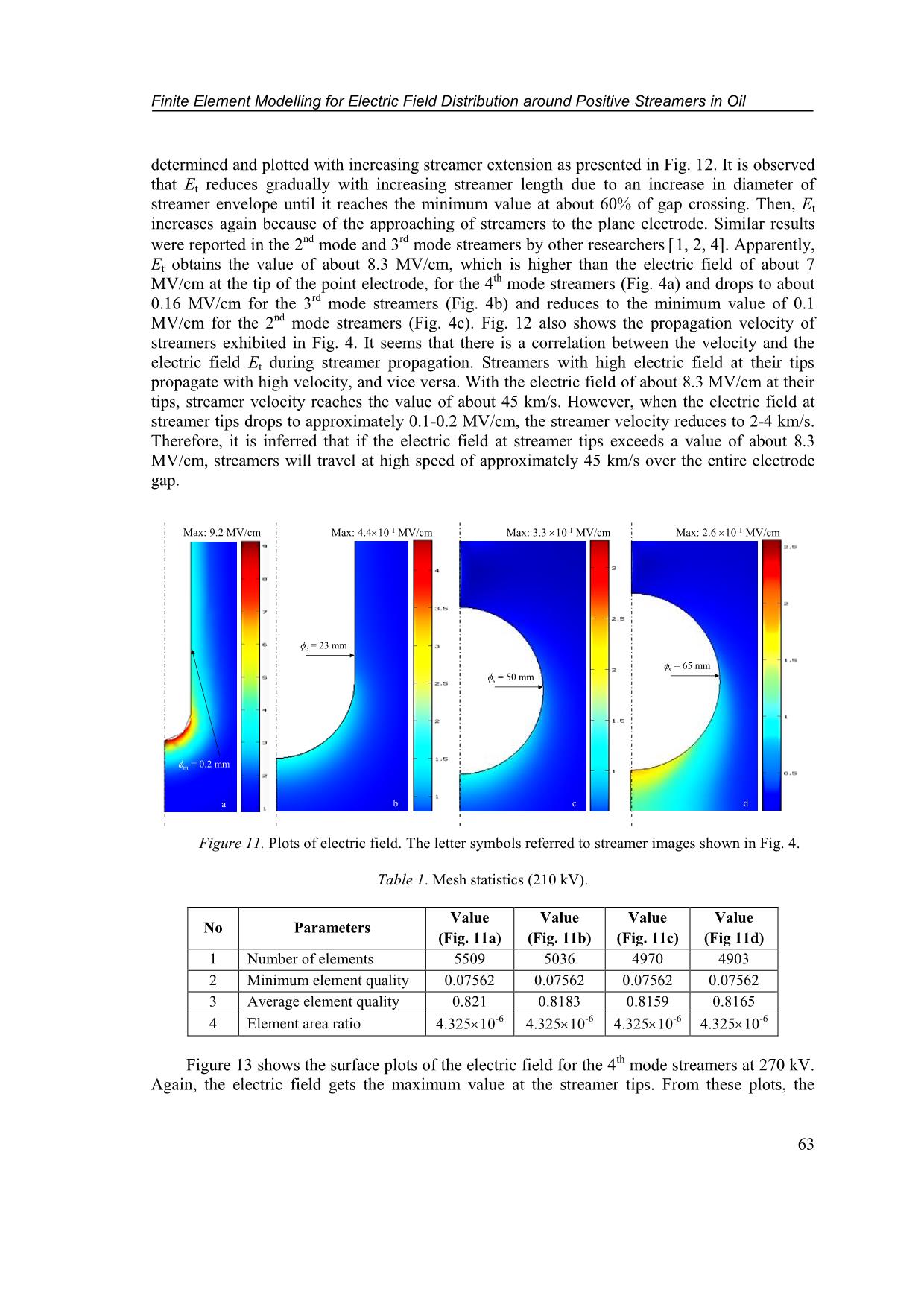
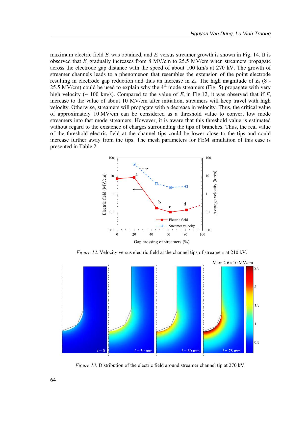
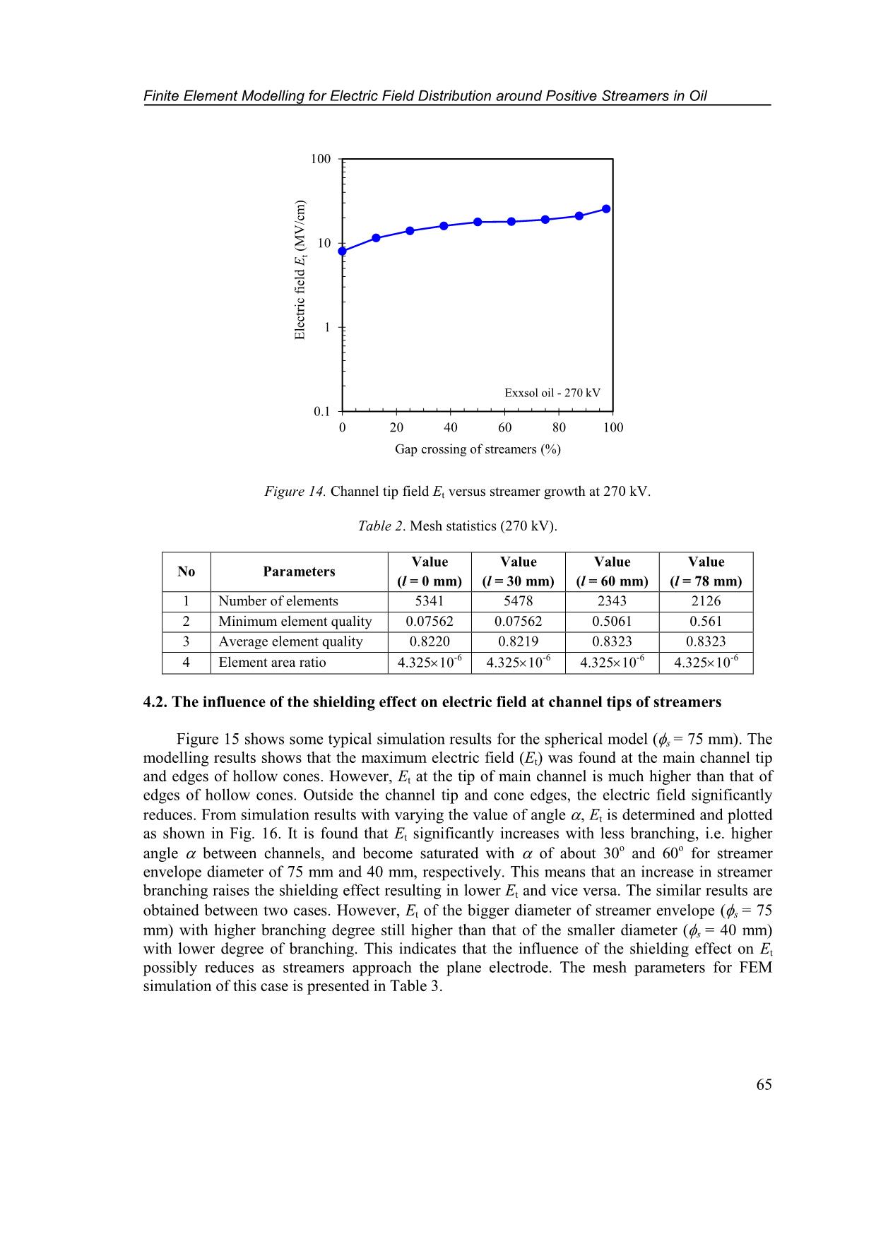
equation shown in (3) can be established from equation (1) and equation (2) s (a) z r Main channel Surrounding channels (b) Plane electrode Point electrode Hollow cones Main channel m= 0.1mm Channel tip field Et Rotational symmetry s t = 0.05 mm Nguyen Van Dung, Le Vinh Truong 62 r V 0 2 (3) As the charge ρ = 0, the Poisson’s equation can be converted into Laplace’s equation as follows 0 2 V (4) For 2D axial symmetry problem, the distribution of potential is dependent upon the coordinate. Thus, the equation (4) is rewritten as follows 0 12 z V zr V r rr V (5) The FEM method reported in references 8-9 is used to solve equation (5) as all boundary conditions are known. An open domain is applied to the point-plane gap problem, i.e. the electric field is zero at infinity. For simplification of simulation, the outermost boundaries are at infinity. Due to these assumptions, the conditions of boundary are set as bellows. V = Vapplied on the point electrode (high voltage); V = 0 on the plane electrode (ground); nD = 0 on outermost boundaries Figure 10 shows the typical mesh of one case of simulation with elements of triangles. The density of elements is higher while its size is smaller for regions around electrodes and streamer branches. Similar results were observed for other cases. Figure 10. The mesh of the model for simulation of shielding effect ( = 75 mm, = 5o). 4. RESULTS AND DISCUSSION 4.1. The electric field distribution in the electrode gap Figure 11 shows the distribution of electric field around streamers at 210 kV derived from simulation results with mesh parameters shown in Table 1. The electric field reaches the maximum value (Et) at the surface of streamer envelope in the direction of gap axis, and decreases with an increase in distance away from a streamer region. From Fig. 11, Et is Finite Element Modelling for Electric Field Distribution around Positive Streamers in Oil 63 determined and plotted with increasing streamer extension as presented in Fig. 12. It is observed that Et reduces gradually with increasing streamer length due to an increase in diameter of streamer envelope until it reaches the minimum value at about 60% of gap crossing. Then, Et increases again because of the approaching of streamers to the plane electrode. Similar results were reported in the 2 nd mode and 3 rd mode streamers by other researchers 1, 2, 4. Apparently, Et obtains the value of about 8.3 MV/cm, which is higher than the electric field of about 7 MV/cm at the tip of the point electrode, for the 4 th mode streamers (Fig. 4a) and drops to about 0.16 MV/cm for the 3 rd mode streamers (Fig. 4b) and reduces to the minimum value of 0.1 MV/cm for the 2 nd mode streamers (Fig. 4c). Fig. 12 also shows the propagation velocity of streamers exhibited in Fig. 4. It seems that there is a correlation between the velocity and the electric field Et during streamer propagation. Streamers with high electric field at their tips propagate with high velocity, and vice versa. With the electric field of about 8.3 MV/cm at their tips, streamer velocity reaches the value of about 45 km/s. However, when the electric field at streamer tips drops to approximately 0.1-0.2 MV/cm, the streamer velocity reduces to 2-4 km/s. Therefore, it is inferred that if the electric field at streamer tips exceeds a value of about 8.3 MV/cm, streamers will travel at high speed of approximately 45 km/s over the entire electrode gap. Figure 11. Plots of electric field. The letter symbols referred to streamer images shown in Fig. 4. Table 1. Mesh statistics (210 kV). No Parameters Value (Fig. 11a) Value (Fig. 11b) Value (Fig. 11c) Value (Fig 11d) 1 Number of elements 5509 5036 4970 4903 2 Minimum element quality 0.07562 0.07562 0.07562 0.07562 3 Average element quality 0.821 0.8183 0.8159 0.8165 4 Element area ratio 4.325 10-6 4.325 10-6 4.325 10-6 4.325 10-6 Figure 13 shows the surface plots of the electric field for the 4 th mode streamers at 270 kV. Again, the electric field gets the maximum value at the streamer tips. From these plots, the Max: 9.2 MV/cm Max: 4.4 10-1 MV/cm Max: 3.3 10-1 MV/cm Max: 2.6 10-1 MV/cm a b c d c = 23 mm s = 50 mm s = 65 mm m = 0.2 mm Nguyen Van Dung, Le Vinh Truong 64 maximum electric field Et was obtained, and Et versus streamer growth is shown in Fig. 14. It is observed that Et gradually increases from 8 MV/cm to 25.5 MV/cm when streamers propagate across the electrode gap distance with the speed of about 100 km/s at 270 kV. The growth of streamer channels leads to a phenomenon that resembles the extension of the point electrode resulting in electrode gap reduction and thus an increase in Et. The high magnitude of Et (8 - 25.5 MV/cm) could be used to explain why the 4 th mode streamers (Fig. 5) propagate with very high velocity ( 100 km/s). Compared to the value of Et in Fig.12, it was observed that if Et increase to the value of about 10 MV/cm after initiation, streamers will keep travel with high velocity. Otherwise, streamers will propagate with a decrease in velocity. Thus, the critical value of approximately 10 MV/cm can be considered as a threshold value to convert low mode streamers into fast mode streamers. However, it is aware that this threshold value is estimated without regard to the existence of charges surrounding the tips of branches. Thus, the real value of the threshold electric field at the channel tips could be lower close to the tips and could increase further away from the tips. The mesh parameters for FEM simulation of this case is presented in Table 2. Figure 12. Velocity versus electric field at the channel tips of streamers at 210 kV. Figure 13. Distribution of the electric field around streamer channel tip at 270 kV. 0,01 0,1 1 10 100 0,01 0,1 1 10 100 0 20 40 60 80 100 A v er ag e v el o ci ty ( k m /s ) E le ct ri c fi el d ( M V /c m ) Gap crossing of streamers (%) Electric field Streamer velocity a b c d Max: 2.6 10 MV/cm l = 0 l = 30 mm l = 60 mm l = 78 mm 2.5 2 1.5 1 0.5 Finite Element Modelling for Electric Field Distribution around Positive Streamers in Oil 65 Figure 14. Channel tip field Et versus streamer growth at 270 kV. Table 2. Mesh statistics (270 kV). No Parameters Value (l = 0 mm) Value (l = 30 mm) Value (l = 60 mm) Value (l = 78 mm) 1 Number of elements 5341 5478 2343 2126 2 Minimum element quality 0.07562 0.07562 0.5061 0.561 3 Average element quality 0.8220 0.8219 0.8323 0.8323 4 Element area ratio 4.325 10-6 4.325 10-6 4.325 10-6 4.325 10-6 4.2. The influence of the shielding effect on electric field at channel tips of streamers Figure 15 shows some typical simulation results for the spherical model (s = 75 mm). The modelling results shows that the maximum electric field (Et) was found at the main channel tip and edges of hollow cones. However, Et at the tip of main channel is much higher than that of edges of hollow cones. Outside the channel tip and cone edges, the electric field significantly reduces. From simulation results with varying the value of angle , Et is determined and plotted as shown in Fig. 16. It is found that Et significantly increases with less branching, i.e. higher angle between channels, and become saturated with of about 30o and 60o for streamer envelope diameter of 75 mm and 40 mm, respectively. This means that an increase in streamer branching raises the shielding effect resulting in lower Et and vice versa. The similar results are obtained between two cases. However, Et of the bigger diameter of streamer envelope (s = 75 mm) with higher branching degree still higher than that of the smaller diameter (s = 40 mm) with lower degree of branching. This indicates that the influence of the shielding effect on Et possibly reduces as streamers approach the plane electrode. The mesh parameters for FEM simulation of this case is presented in Table 3. 0.1 1 10 100 0 20 40 60 80 100 E le ct ri c fi el d E t (M V /c m ) Gap crossing of streamers (%) Exxsol oil - 270 kV Nguyen Van Dung, Le Vinh Truong 66 Figure 15. The distribution of electric field for s = 75 mm. Figure 16. The channel tip field versus angle between branches. Main channel Hollow cones Max: 3 10 MV/cm = 5 o = 60 o Main channel Finite Element Modelling for Electric Field Distribution around Positive Streamers in Oil 67 Table 3. Mesh statistics (the shielding effect). No Parameters = 40 mm = 75 mm = 0o = 5o = 60o = 0o = 5o = 60o 1 Number of elements 4955 13876 5791 4890 14679 5796 2 Minimum element quality 0.07562 0.07562 0.07562 0.07562 0.07562 0.07562 3 Average element quality 0.8174 0.803 0.8209 0.8161 0.8035 0.8161 4 Element area ratio 4.33 10-6 2.86 10-11 1.91 10-6 4.33 10-6 2.93 10-11 4.33 10-6 4.3. The relationship among electric field, branching and velocity From Fig. 4, Fig. 5, Fig. 12, Fig. 14 and Fig. 16, it is observed that the 2 nd mode streamers consisting of numerous filamentary branches propagate with the velocity of about 1-2 km/s, and the electric field at the channel tips of streamers is estimated to be about 0.13-0.19 MV/cm. It is also obtained that the 3 rd mode streamers propagating with velocity of about 4-10 km/s has the electric field at their tips of about 0.2 MV/cm. The 4 th mode streamers with few branches travel with velocity of 50 km/s-100 km/s and reach the estimated field at the streamer tips of about 8- 25.5 MV/cm. This indicates that more branching, which is manifested with high number of branches, is associated with low velocity (1-2 km/s) and low electric field ( 0.2 MV/cm) at the streamer channel tips and vice versa. Therefore, the relationship between branching and velocity of positive streamers is suggested as follows. Streamers initiating with the speed of about 1-2 km/s allow the development of branches, i.e. more branching. Due to branching, the macroscopic field of streamers becomes lower leading to a reduction in streamer velocity. By contrast, when streamers start with the high velocity ( 50 km/s), the chance for streamer branches to develop is low. Therefore, the electric field in front of the dominating branches raises greatly, which further increases the speed of streamers. The relationship among velocity, branching and electric field is summarized as shown in Fig. 17. This suggested hypothesis is also supported by experimental results that streamer propagation across the electrode gap was observed to be controlled by the macroscopic electric field of streamers 5, and guiding tubes that suppressed branching accelerated streamers 4, 10. Figure 17. The diagram describing the correlation between branching and velocity of streamers. Low velocity More branching High velocity Less branching Reduced macroscopic/ microscopic field Increased macroscopic/ microscopic field High electric field (10 MV/cm) Streamers start at the point electrode Terminating at the plane electrode Yes No Nguyen Van Dung, Le Vinh Truong 68 4. CONCLUSIONS Simulation of electric field distribution for positive streamers during propagation and the influence of the shielding effect on the electric field were performed. The simulation results show that the electric field reduces with streamer extension and reaches the minimum value at the position of about 60 % of the electrode gap before increases again due to streamer proximity to the plane electrode. The channel tip field of streamers at the 2 nd mode is determined to be about 0.1 MV/cm while 8.3 MV/cm was received for the 4 th mode streamers. It was also observed that the shielding effect formed by streamer branching greatly reduces the electric field at streamer channel tips. The shielding effect reduces with increasing the angle between channels and has a tendency of saturation at the angle of about 60o and 30o for 40 mm and 75 mm of diameters of streamer envelope, respectively. The hypothesis on the relationship among electric field, velocity and branching of streamers is proposed as follows. If starting with high electric field at the tips (10 MV/cm), streamers will propagate with very high velocity which results in less branching and thus high electric field (10 MV/cm) which further raises the velocity, and vice versa. However, the accuracy of the hypothesis should be further checked with simulation results from higher applied voltage, e.g. 540 kV, in next study. REFERENCES 1. Beroual A., Tobazeon R. - Prebreakdown phenomena in liquid dielectrics, IEEE Trans. Electr. Insul. 21 (4) (1986) 613-627. 2. Lundgaard L., Linhjell D., Berg G., Sigmond S. - Propagation of positive and negative streamers in oil with and without pressboard interfaces, IEEE Trans. Dielectr. Electr. Insul. 5 (3) (1998) 388-395. 3. Lesaint O., Massala G. - Positive streamer propagation in large oil gaps: Experiment characterization of propagation modes, IEEE Trans. Dielectr. Electr. Insul. 5 (3) (1998) 360-370. 4. Massala G., Lesaint O. - Positive streamer propagation in large oil gaps: Electrical properties of streamers, IEEE Trans. Dielectr. Electr. Insul. 5 (3) (1998) 371-381. 5. Top T.V.., Massala G., Lesaint O. - Streamer propagation in mineral oil in semi-uniform geometry, IEEE Trans. Dielectr. Electr. Insul. 9 (1) (2002) 76-83. 6. Dung N.V., Mauseth F., Hoidalen H.K., Linhjell D., Ingebrigtsen S., Lundgaard L.E., Ung M. - Streamers in large paraffinic oil gap, Proceeding of the 17 th ICDL, Trondheim, Norway, (2011) 1-6. 7. Dung N.V., Hoidalen H.K., Linhjell D., Lundgaard L.E., Ung M. - Effects of reduced pressure and additives on streamers in white oil in long point-plane gap, Journal of Physics D: Applied Physics 46 (2013) 1-16. 8. Ming L., Jiang Z., Gang L. - Simulation Analysis of Flashover Characteristics of 220kV Composite Insulators Based on Finite-Element Method, Proceeding of the International Conference on Properties and Applications of Dielectric Materials, Harbin, China (2009) 697-700. Finite Element Modelling for Electric Field Distribution around Positive Streamers in Oil 69 9. Muniraj C., Chandrasekar S. - Finite Element Modeling for Electric Field and Voltage Distribution along the Polluted Polymeric Insulator, World Journal of Modelling and Simulation 8 (2012) 310-320. 10. Dung N.V., Hoidalen H.K., Linhjell D., Ingebrigtsen S., Lundgaard L.E., Ung M. - Effects of spatial restriction on streamers in white oil, Proceeding of the 18 th ICDL, Bled, Slovenia, (2014) 1-4.
File đính kèm:
 finite_element_modelling_for_electric_field_distribution_aro.pdf

