Control of two - wheeled inverted pendulum robot using robust pi and lqr controllers
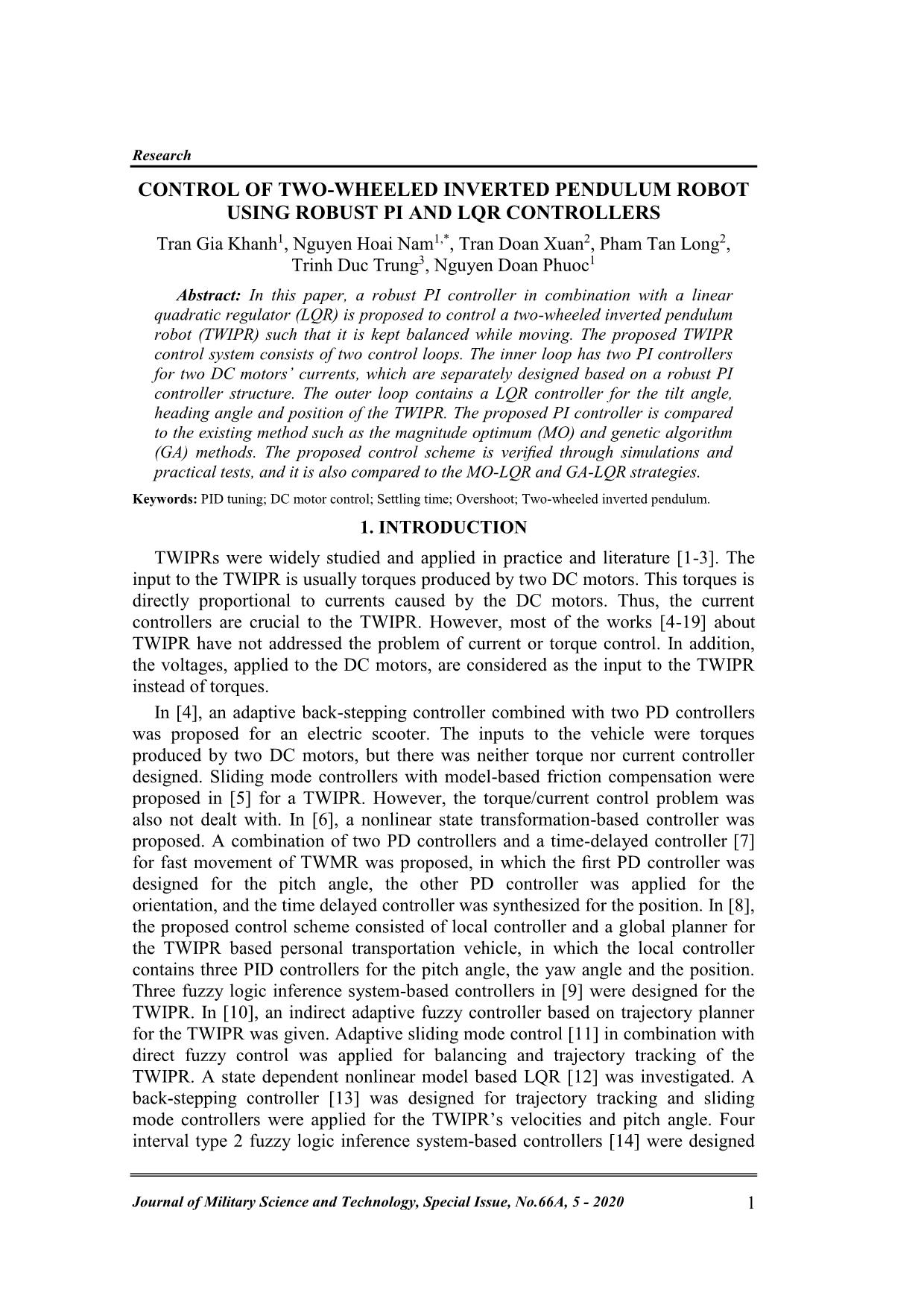
In this paper, a robust PI controller in combination with a linear
quadratic regulator (LQR) is proposed to control a two-wheeled inverted pendulum
robot (TWIPR) such that it is kept balanced while moving. The proposed TWIPR
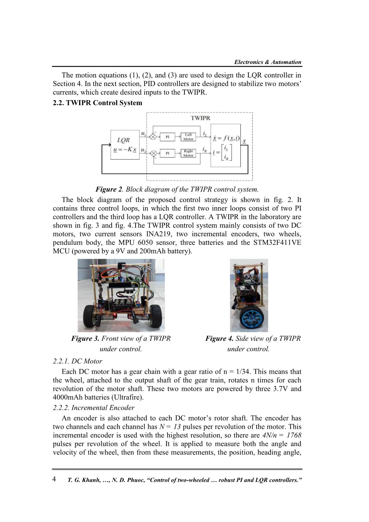
control system consists of two control loops. The inner loop has two PI controllers
for two DC motors’ currents, which are separately designed based on a robust PI
controller structure. The outer loop contains a LQR controller for the tilt angle,
heading angle and position of the TWIPR. The proposed PI controller is compared
to the existing method such as the magnitude optimum (MO) and genetic algorithm
(GA) methods. The proposed control scheme is verified through simulations and
practical tests, and it is also compared to the MO-LQR and GA-LQR strategies.
Trang 1
Trang 2
Trang 3
Trang 4
Trang 5
Trang 6
Trang 7
Trang 8
Trang 9
Trang 10
Tải về để xem bản đầy đủ
Tóm tắt nội dung tài liệu: Control of two - wheeled inverted pendulum robot using robust pi and lqr controllers
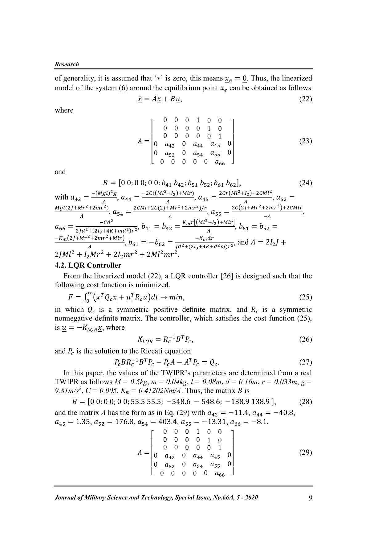
 𝑏62], (24)
with 𝑎42 =
−(𝑀𝑔𝑙)2𝑔
𝛬
, 𝑎44 =
−2𝐶((𝑀𝑙2+𝐼2)+𝑀𝑙𝑟)
𝛬
, 𝑎45 =
2𝐶𝑟(𝑀𝑙2+𝐼2)+2𝐶𝑀𝑙
2
𝛬
, 𝑎52 =
𝑀𝑔𝑙(2𝐽+𝑀𝑟2+2𝑚𝑟2)
𝛬
, 𝑎54 =
2𝐶𝑀𝑙+2𝐶(2𝐽+𝑀𝑟2+2𝑚𝑟2)/𝑟
𝛬
, 𝑎55 =
2𝐶(2𝐽+𝑀𝑟2+2𝑚𝑟3)+2𝐶𝑀𝑙𝑟
−𝛬
,
𝑎66 =
−𝐶𝑑2
2𝐽𝑑2+(2𝐼3+4𝐾+𝑚𝑑2)𝑟2
, 𝑏41 = 𝑏42 =
𝐾𝑚𝑟[(𝑀𝑙
2+𝐼2)+𝑀𝑙𝑟]
𝛬
, 𝑏51 = 𝑏52 =
−𝐾𝑚(2𝐽+𝑀𝑟
2+2𝑚𝑟2+𝑀𝑙𝑟)
𝛬
, 𝑏61 = −𝑏62 =
−𝐾𝑚𝑑𝑟
𝐽𝑑2+(2𝐼3+4𝐾+𝑑2𝑚)𝑟2
, and 𝛬 = 2𝐼2𝐽 +
2𝐽𝑀𝑙2 + 𝐼2𝑀𝑟
2 + 2𝐼2𝑚𝑟
2 + 2𝑀𝑙2𝑚𝑟2.
4.2. LQR Controller
From the linearized model (22), a LQR controller [26] is designed such that the
following cost function is minimized.
𝐹 = ∫ (𝑥𝑇𝑄𝑐𝑥 + 𝑢
𝑇𝑅𝑐𝑢)𝑑𝑡
∞
0
→ 𝑚𝑖𝑛, (25)
in which 𝑄𝑐 is a symmetric positive definite matrix, and 𝑅𝑐 is a symmetric
nonnegative definite matrix. The controller, which satisfies the cost function (25),
is 𝑢 = −𝐾𝐿𝑄𝑅𝑥, where
𝐾𝐿𝑄𝑅 = 𝑅𝑐
−1𝐵𝑇𝑃𝑐, (26)
and 𝑃𝑐 is the solution to the Riccati equation
𝑃𝑐𝐵𝑅𝑐
−1𝐵𝑇𝑃𝑐 − 𝑃𝑐𝐴 − 𝐴
𝑇𝑃𝑐 = 𝑄𝑐. (27)
In this paper, the values of the TWIPR’s parameters are determined from a real
TWIPR as follows M = 0.5kg, m = 0.04kg, l = 0.08m, d = 0.16m, r = 0.033m, g =
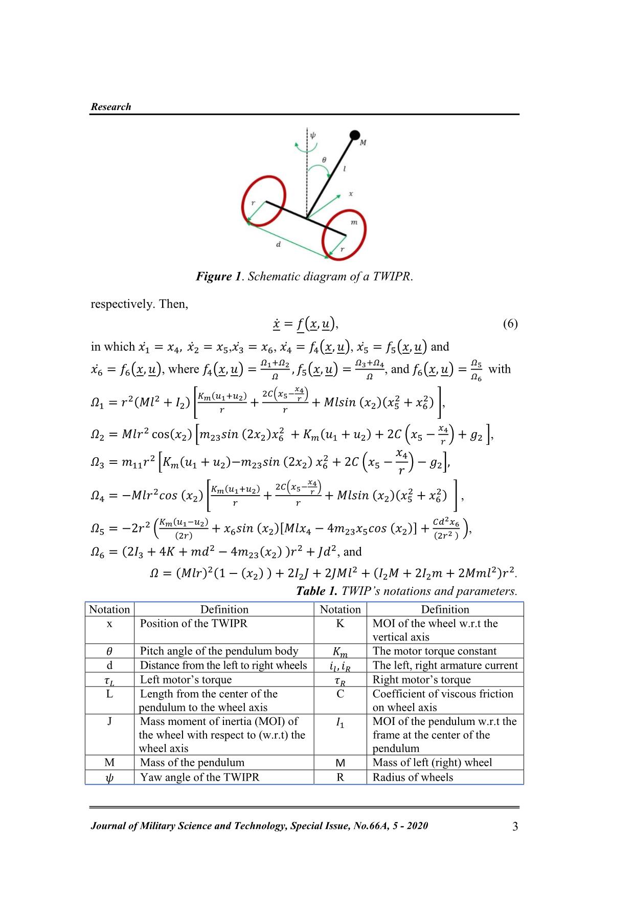
9.81m/s2, C = 0.005, Km = 0.41202Nm/A. Thus, the matrix B is
 𝐵 = [0 0; 0 0; 0 0; 55.5 55.5; −548.6 − 548.6; −138.9 138.9 ], (28)
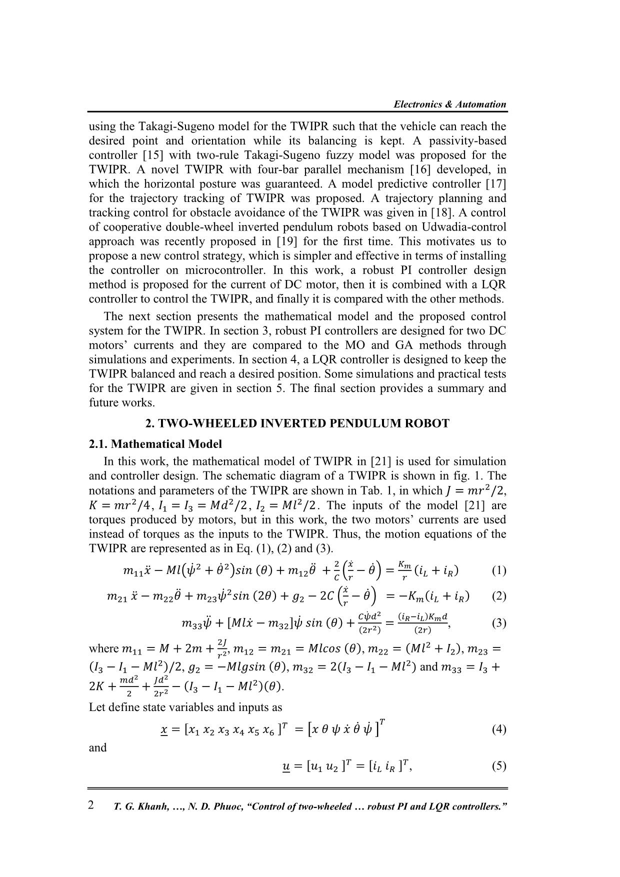
and the matrix A has the form as in Eq. (29) with 𝑎42 = −11.4, 𝑎44 = −40.8,
𝑎45 = 1.35, 𝑎52 = 176.8, 𝑎54 = 403.4, 𝑎55 = −13.31, 𝑎66 = −8.1.
𝐴 =
[
0 0 0 1 0 0
0 0 0 0 1 0
0 0 0 0 0 1
0 𝑎42 0 𝑎44 𝑎45 0
0 𝑎52 0 𝑎54 𝑎55 0
0 0 0 0 0 𝑎66 ]
 (29)
Electronics & Automation
T. G. Khanh, , N. D. Phuoc, “Control of two-wheeled  robust PI and LQR controllers.” 10
The matrices of the cost function are chosen as
𝑄𝑐 = 𝑑𝑖𝑎𝑔([4, 3, 2, 3.5, 0.001, 0.9 ]) (30)
and
𝑅𝑐 = [1 0; 0 1 ]. (31)
From Eq. (26) and Eq. (27), the gain matrix of the LQR controller is obtained as
 𝐾𝐿𝑄𝑅 = [
−1.41 −3.09 −3.16 −2.14 −0.33 −0.65
−1.41 −3.09 3.16 −2.14 −0.33 0.65
] . (32)
The output of the LQR controller will be setpoint for the current controllers.
Remark 3. Since the input to the LQR controller consists of state variable pairs
(x;�̇�), (θ;�̇�) and (ψ;�̇�), the LQR output is similar to the sum of the three PD
controllers’ output as in works [4, 7, 8], in which each state variable pair is the
input to one PD controller.
Remark 4. The LQR controller in [12] is also compared to the state dependent
LQR controller when the high yaw rate is considered.
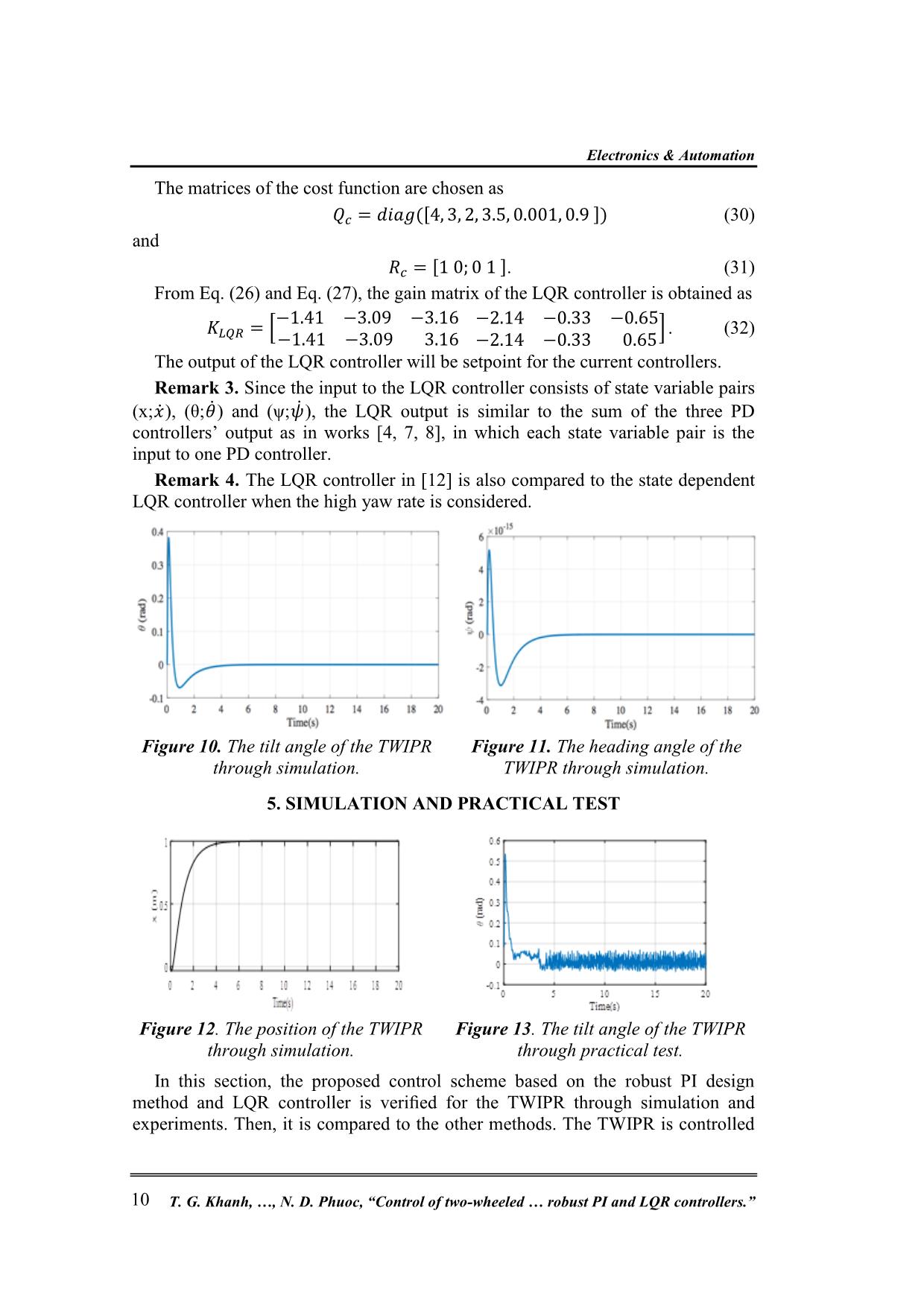
Figure 10. The tilt angle of the TWIPR
through simulation.
Figure 11. The heading angle of the
TWIPR through simulation.
5. SIMULATION AND PRACTICAL TEST
Figure 12. The position of the TWIPR
through simulation.
Figure 13. The tilt angle of the TWIPR
through practical test.
In this section, the proposed control scheme based on the robust PI design
method and LQR controller is verified for the TWIPR through simulation and
experiments. Then, it is compared to the other methods. The TWIPR is controlled
Research
Journal of Military Science and Technology, Special Issue, No.66A, 5 - 2020 11
to move from the initial point to the end point along a line, where the distance
between these two points is 1 meter.
5.1. The proposed control strategy
The simulation results are shown in fig. 10, 11 and 12 whereas the experimental
results are shown in fig. 13, 14 and 15. The left motor’s measured current and right
motor’s measured current are shown in fig. 16 and 17. For simulation, the origin
model as Eq. (6) and its parameters given in section 4.2 are applied for the TWIPR,
in which the current control loops are modeled as saturation blocks since their
settling time is very short 1 (ms).
Figure 14. The real heading angle of
the TWIPR.
Figure 15. The real position of
the TWIPR.
For experimental test, the sampling time for PID and LQR controllers is chosen
as 0.25 (ms) and 2.5 (ms), respectively. From fig. 10 to fig. 15, it can be implies
that the real-time results are similar to the simulation results. This implies that a
good model of the TWIPR was built and the controllers work well. The proposed
control strategy produces good performance such as the pitch angle lies within the
interval [−3 3] (degrees), the TWIPR reaches the destination at 1 (m) after 3.5
(seconds) following a straight line because the yaw angle is approximately within
the range [−0.3 0.3] (degrees).
5.2. Comparisons
The proposed control scheme based on the robust PI-LQR method is compared
to the MO-LQR and GA-LQR methods through practical tests. The desired
trajectory is a straight line with a length of 1 meter. Fig. 18 shows the positions of
the TWIPR with different methods, where the blue curve, the black curve and the
red curve are positions of the TWIPR provided by the proposed method, the MO-
LQR method and the GA-LQR method, respectively.
The comparison of the pitch and yaw angles of the TWIPR with different
methods are shown in fig. 19 and fig. 20, respectively. Since the yaw angles are
very small for all methods, the TWIPR moves nearly along the straight line with
distance of 1 meter. The robust PI-LQR based TWIPR moves more smoothly from
the start point 0 to the end point with smaller pitch angle and less oscillation than
the other methods. Hence, the proposed controller provides better performance
than the others.
Electronics & Automation
T. G. Khanh, , N. D. Phuoc, “Control of two-wheeled  robust PI and LQR controllers.” 12
Figure 16. Left motor’s real current.
Figure 17. Right motor’s real current.
Figure 18. The position of the TWIPR with different methods.
Figure 19. The pitch angle of the
TWIPR with different methods.
Figure 20. The yaw angle of the TWIPR
with different methods.
Remark 5: The proposed control scheme is also tested with different loads and
inclined surfaces. The practical results prove that the TWIPR is kept balanced and
movable. However, they are skipped to show here.
6. CONCLUSIONS
In this work, the TWIPR control system based on the robust PI controller design
method is proposed. First, the proposed method is compared to the MO and GA
Research
Journal of Military Science and Technology, Special Issue, No.66A, 5 - 2020 13
methods through the DC motor’s current. It produces better performance than the
others. Then, the proposed control system is verified and compared to the other
methods through simulations and practical tests. The obtained results show that the
TWIPR with the proposed method is kept balanced and able to reach the desired
position and direction, and it produces better performance than the others. Future
works will focus on the combination of the proposed method with other advanced
control methods for the TWIPR.
ACKNOWLEDGEMENT
This research is funded by the Hanoi University of Science and Technology
(HUST) under project number T2018-PC-052.
REFERENCES
[1]. A. L. Cullen, "A new free-wave method for ferrite measurements at millimeter
wavelengths," Radio Science, Vol. 22, pp. 1168-1170, (1987).
[2]. L. Zhijun, Y. Chenguang, and F. Liping, “Advanced Control of Wheeled
Inverted Pendulum Systems,” Springer, 280, (2013).
[3]. P. M. C. Ronald, A. S. Karl, and H. Roger, “Review of modeling and control of
two-wheeled robots,” Annual Reviews in Control, Vol. 37, pp. 89-103, (2013).
[4]. T. G. Khanh, N. D. Phuoc, and N. H. Nam, “Advanced control methods for
two-wheeled mobile robots,” The proceedings of the International Conference
on System Science and Engineering. Ho Chi Minh, Vietnam, (2017).
[5]. N. N. Son and P. H. H. Anh, “Adaptive Back-stepping Self-balancing Control
of a Two-wheel Electric Scooter,” Int. Jour. Advan. Robo. Syst., Vol. 11, pp.
1–11, (2014).
[6]. D. Fuquan, G. Xueshan, J. Shigong, G. Wenzeng, and L. Yubai, “A two-
wheeled inverted pendulum robot with friction compensation,” Mechatronics
Vol. 30, pp. 116–125. (2015).
[7]. R. M. Brisilla and V. Sankaranarayanan, “Nonlinear control of mobile
inverted pendulum,” Robotics and Autonomous Systems, Vol. 70, pp. 145–
155, (2015).
[8]. T. C. Sung and J. Seul, “Combining Two Control Techniques for the Fast
Movement of a Two-Wheel Mobile Robot,” Int. J. Human. Robot, Vol. 12, pp.
1–14, (2015).
[9]. H. W. Kim and S. Jung, “Control of a two-wheel robotic 300 vehicle for
personal transportation,” Robotica, Vol. 34, pp. 1186– 1208, (2016).
[10]. O. Akos, B. Ervin, K. Istvan, F. Janos and O. A. Peter, Fuzzy Control of a
Two-Wheeled Mobile Pendulum System,” Proceedings of the 11th IEEE Int.
Symp. Appl. Comp. Intel. and Infor., Romania, (2016).
[11]. Y. Ming, A. Cong, D. Yu and S. Jianzhong, “Indirect adaptive fuzzy control
for a nonholonomic/underactuated wheeled inverted pendulum vehicle based
on a data-driven trajectory planner,” Fuzzy Sets and Systems, Vol. 290, pp.
158–177, (2016).
[12]. Y. Ming, W. Shuang and S. Jian-Zhong, “Simultaneous balancing and
trajectory tracking control for two-wheeled inverted pendulum vehicles: A
Electronics & Automation
T. G. Khanh, , N. D. Phuoc, “Control of two-wheeled  robust PI and LQR controllers.” 14
composite control approach,” Neurocomputing Vol. 191, pp.44–54, (2016).
[13]. K. Sangtae and K. SangJoo, “Nonlinear Optimal Con315 trol Design for
Underactuated Two-Wheeled Inverted Pendulum Mobile Platform,”
IEEE/ASME Transactions on Mechatronics, Vol. 22, pp. 2803 – 2808, (2017).
[14]. N. Esmaeili, A. Alireza and K. Hossein, “Balancing and Trajectory Tracking
of Two-Wheeled Mobile Robot Using Backstepping Sliding Mode Control:
Design and Experiments,” Journal of Intelligent and Robotic Systems, Vol.
83, pp. 601–613, (2017).
[15]. H. Jian, H. R. Myong, W. Dongrui and R. Songhyok, “Interval Type-2 Fuzzy
Logic Modeling and Control of a Mobile Two-Wheeled Inverted Pendulum,”
IEEE Transactions on Fuzzy Systems, Vol. 26, pp. 2030–2038, (2018).
[16]. L. Rongjun, W. Junfeng, W. Dan, “Sampled-data Fuzzy Control of Two-
wheel Inverted Pendulums Based on Passivity Theory,” International Journal
of Control, Automation and Systems, Vol. 16, pp. 2538-2548, (2018).
[17]. J. Seonghee and H. Taisei, “Development of a wheeled inverted pendulum
mobile platform with a four-bar parallel mechanism,” Advanced Robotics,
Vol. 32, pp. 1–11, (2018).
[18]. Y. Ming, A. Cong and S. Jian-Zhong, “An Efficient Model Predictive Control
for Trajectory Tracking of Wheeled Inverted Pendulum Vehicles with Various
Physical Constraints,” International Journal of Control, Automation and
Systems, Vol. 16, pp. 265–274, (2018).
[19]. N. Yigao, Y. Ming, Y. Lu and H. Xiaoqiang, “A trajectory planning and
tracking control approach for obstacle avoidance 340 of wheeled inverted
pendulum vehicles,” International Journal of Control,
https://doi.org/10.1080/00207179.2018.1530455 (2018).
[20]. H. Chunsheng, H. Kang, C. Xiaolong, Z. Yiran and Z. Han “Transportation
control of cooperative double-wheel inverted pendulum robots adopting Udwadia-
control approach,” Nonlinear Dynamics, Vol. 91, pp. 2789–2802, (2018).
[21]. N. H. Nam and N. D. Phuoc, “Overshoot and settling time assignment with
pid for first order and second-order systems,” IET Control Theory and
Applications, Vol. 12, pp. 2407– 2416, (2018).
[22]. K. Sangtae and K. SangJoo, “Dynamic Modeling of a Two-wheeled Inverted
Pendulum Balancing Mobile Robot,” International Journal of Control,
Automation, and Systems, Vol. 13, pp. 926–933, (2015).
[23]. G. B. Robert and Y. C. H. Patrick, “Introduction to Random Signals and
Applied Kalman Filtering with Matlab Exercises,” Fourth Edition, John
Wiley and Sons, Inc, (2012).
[24]. P. Jinzhu and D. Rickey, “Identification and adaptive neural network control
of a DC motor system with dead-zone characteristics,” ISA Transactions,
Vol. 50, pp. 588–598, (2011).
[25]. W. U. Jeffrey and S. Mohammed, “Magnitude and symmetric optimum criterion
for the design of linear control systems: What is it and how does it compare with
the others?,” IEEE Trans. Indus. Appl., Vol. 26, pp. 489–497, (1990).
[26]. T. Neenu and P. Poongodi, “Position Control of DC Motor Using Genetic
Algorithm Based PID Controller,” Proc. Worl. Cong. Engineering, London
Research
Journal of Military Science and Technology, Special Issue, No.66A, 5 - 2020 15
UK, pp. 1–5, (2009).
[27]. D. O. A. Brian and B. M. John, “Optimal Control: Linear Quadratic
Methods,” Prentice-Hall International, Inc, (1989).
[28]. T. G. Khánh, L. V. Anh, P. A. Tuấn, P. X. Minh, N. H. Nam, “Điều khiển xe
hai bánh tự cân bằng mô hình bất định dựa trên phương pháp quy hoạch
động thích nghi,” The 1st National Conference on Dynamics and Control,
Danang, Vietnam, (2019).
[29]. N. V. Khanh, T. T. Hùng, “Điều khiển thời gian thực robot hai bánh tự cân
bằng sử dụng bộ điều khiển PID mờ tự chỉnh,” Hội nghị toàn quốc lần thứ 3
về Điều khiển và Tự động hoá, (2015).
[30]. N. M. Tâm, N. V. Đ. Hải, N. P. Lưu, L. V. Tuấn, “Mô hình hóa và điều khiển
tối ưu cho hệ xe hai bánh tự cân bằng,” Đại học Sư phạm Kỹ thuật Hồ Chí
Minh, (2017).
[31]. A. N. K. Nasir, M. A. Ahmad, R. M. T. Raja Ismail, "The Control of a Highly
Nonlinear Two-wheels Balancing Robot: A Comparative Assessment between
LQR and PID-PID Control Schemes," WASET International Journal of
Mechanical and Mechatronics Engineering, Vol. 4, (2010).
[32]. A. Y. Zimit, H. J. Yap, M. F. Hamza, I. Siradjuddin, B. Hendrik, T. Herawan,
"Modeling and Experimental Analysis Two-Wheeled Self Balance Robot
Using PID Controller," Lecture Notes in Computer Science, Vol. 10961,
Springer, Cham, (2018).
TÓM TẮT
ĐIỀU KHIỂN XE HAI BÁNH CÂN BẰNG
SỬ DỤNG BỘ ĐIỀU KHIỂN PI BỀN VỮNG VÀ LQR
Trong bài báo này, một bộ điều khiển PI bền vững kết hợp với bộ điều
khiển LQR được đề xuất được đề xuất để điều khiển xe hai bánh sao cho xe
thằng bằng khi di chuyển. Hệ thống điều khiển gồm hai vòng. Vòng trong có
hai bộ điều khiển dòng PI để điều khiển dòng động cơ một chiều, được thiết kế
riêng sử dụng cấu trúc PI bền vững. Vòng ngoài có bộ điều khiển LQR cho
góc nghiêng, góc hướng và vị trí xe. Phương pháp thiết kế bộ điều khiển PI đề
xuất được so sánh với phương pháp tối ưu độ lớn và giải thuật di truyền. Cấu
trúc điều khiển đề xuất được kiểm chứng thông qua mô phỏng và thực nghiệm,
và nó được so sánh với các phương pháp MO-LQR và GC-LQR.
Từ khóa: Chỉnh định PID; Xe hai bánh; Điều khiển động cơ; Thời gian xác lập.
Received date, 02nd March 2020
Revised date, 14th April 2020
Published 06th May, 2020
Author affiliations:
1Hanoi University of Science and Technology, No. 1, Dai Co Viet Street, Hanoi, Vietnam;
2Viện Hàng không Vũ trụ Viettel;
3Công ty Ô tô Toyota Việt Nam.
*Corresponding author: nam.nguyenhoai@hust.edu.vn.
File đính kèm:
 control_of_two_wheeled_inverted_pendulum_robot_using_robust.pdf

