Control of induction machine drives in overmodulation range
In this paper, a control scheme of a vector-controlled induction machine (IM) drives in
overmodulation (OVM) range to maximize the voltage utilization of the voltage-source
inverter (VSI) has been introduced. In OVM region, a modified voltage reference is produced
for the space-vector pulse-width modulation (SVPWM), which can cause the motor current to
be distorted, leading to the damage of the VSI control operation. To improve the system control
performance, the harmonic current components in the feedback currents needs to be removed
before feeding to the proportional-integral (PI) current controllers. The response of the current
controllers in OVM range has been analyzed, which gives good performance of the system.
The proposed method has been verified by simulation results for 3kW induction motor drives.
Trang 1
Trang 2
Trang 3
Trang 4
Trang 5
Trang 6
Trang 7
Trang 8
Trang 9
Trang 10
Tải về để xem bản đầy đủ
Tóm tắt nội dung tài liệu: Control of induction machine drives in overmodulation range
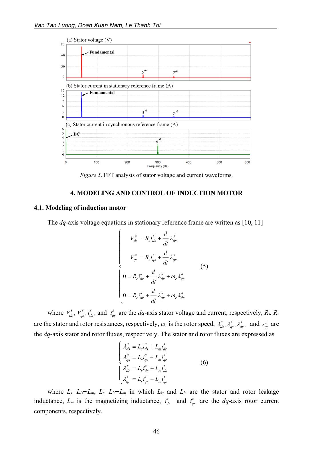
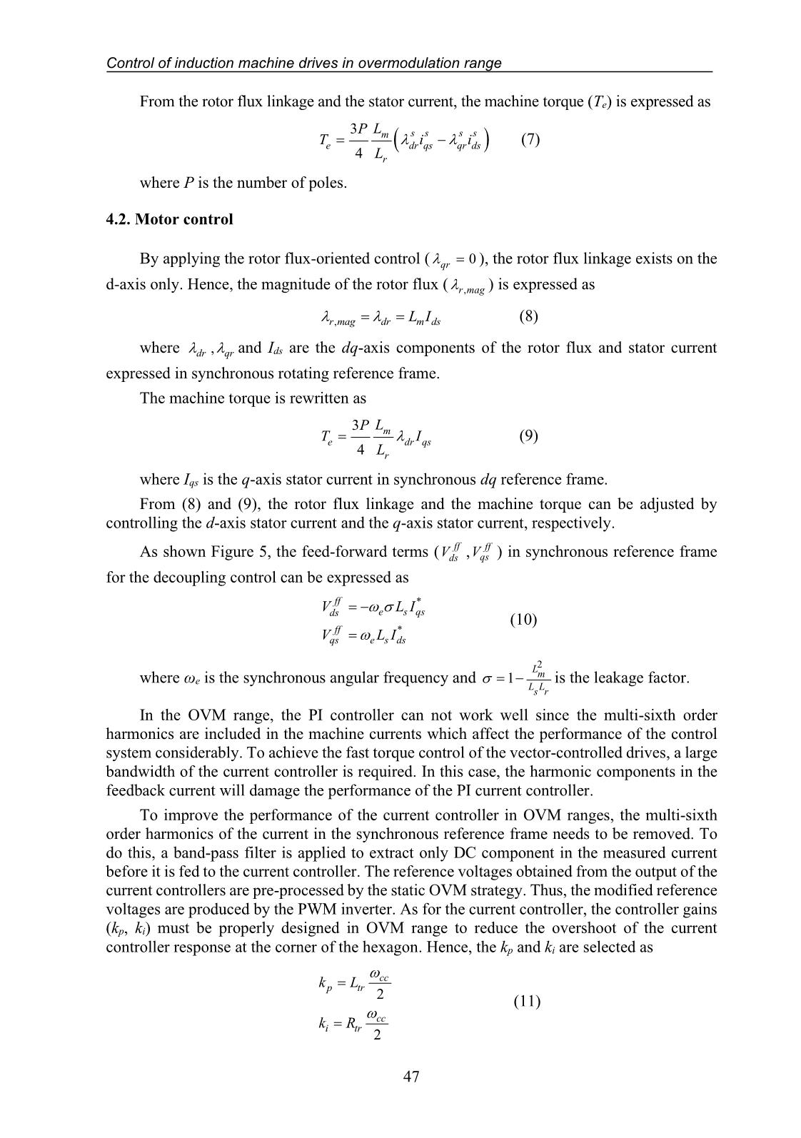
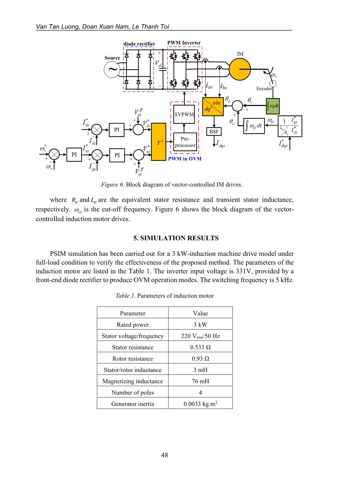
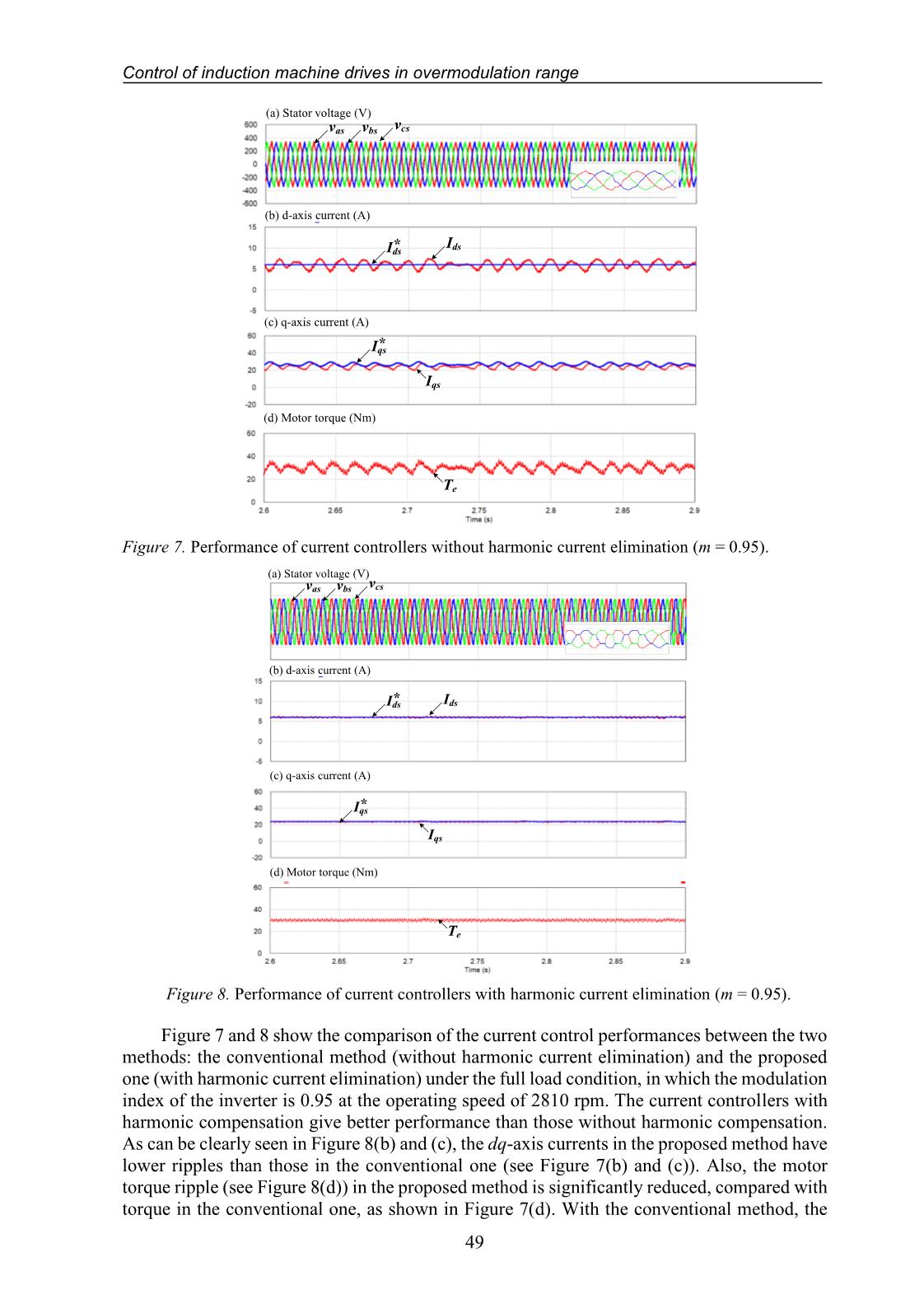
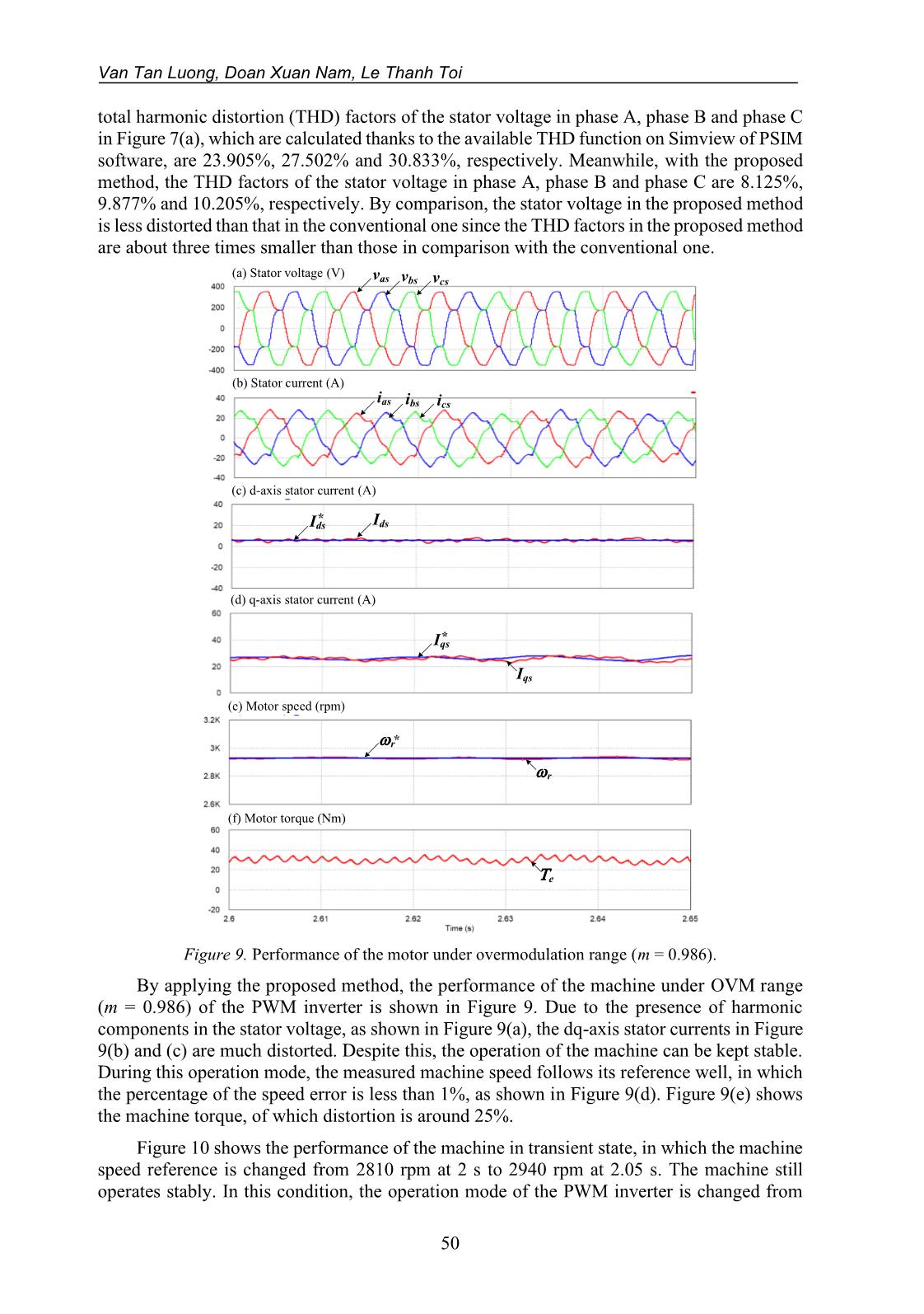
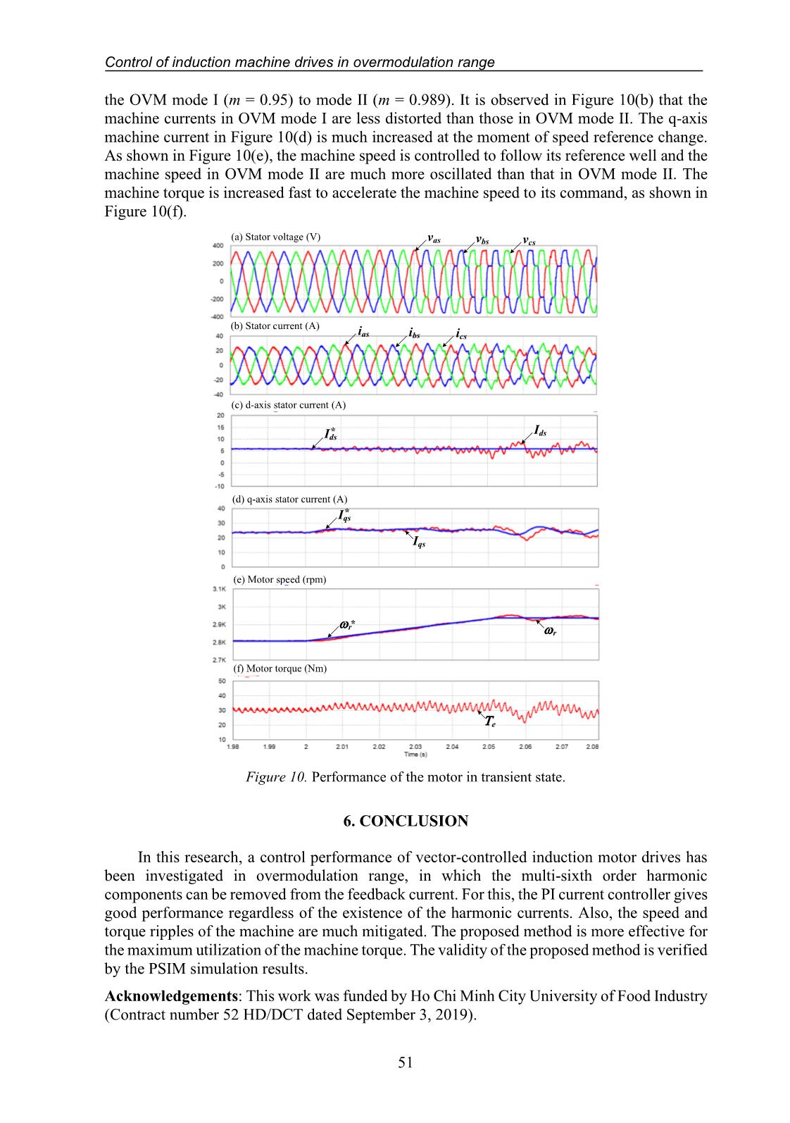
systems. Thus, the presence of the 5th, 7th, 11th, 13th order harmonics and so on should be considered in the output voltage of PWM inverter. The output voltage space vector (us) in the stationary reference frame is expressed as [1, 4] 5 7 11 13 1 5 7 11 13( ) e e e e ej t j t j t j t j tsu u e K e K e K e K e − −= + + + + + (2) where u1 is the fundamental output voltage component and Kj (j = 5, 7, 11, 13, ) is the ratio of nth harmonic component and its fundamental. When the inverter output voltage is fed to the machine, then the harmonic currents in the machine caused by the harmonic voltage components are expressed as 5 7 11 13 1 5 7 11 13( ) e e e e ej t j t j t j t j ts i i i ii i e K e K e K e K e − −= + + + + + (3) where is is the machine current vector in the stationary reference frame, i1 is the fundamental current component, and Kij (j = 5, 7, 11, 13, ) is the ratio of n th harmonic current components to its fundamental value. For vector-controlled machine drives, the machine current controller implemented in the rotating reference frame, in which the machine current vector (ie) is expressed as 6 6 12 12 1 5 7 11 13(1 ) e e e e e j te s j t j t j t j t i i i i i i e i K e K e K e K e − − − = = + + + + + (4) Equation (4) presents the DC quantity and multi-sixth order harmonic current components of the machine. Figure 5 shows the fast Fourier transform (FFT) analysis of the machine current and the inverter output voltage. As can be seen from the figure, the fundamental and fifth- and seventh-order components of stator and currents exist in the stationary reference frame and the DC component and the multi-sixth order harmonics of the stator current appear in the synchronous reference frame. Van Tan Luong, Doan Xuan Nam, Le Thanh Toi 46 (a) Stator voltage (V) Fundamental th 5 th7 (b) Stator current in stationary reference frame (A) Fundamental th 5 th7 (c) Stator current in synchronous reference frame (A) DC th 6 90 60 30 0 15 12 3 0 9 6 6 5 2 0 4 3 1 Figure 5. FFT analysis of stator voltage and current waveforms. 4. MODELING AND CONTROL OF INDUCTION MOTOR 4.1. Modeling of induction motor The dq-axis voltage equations in stationary reference frame are written as [10, 11] 0 0 s s s ds s ds ds s s s qs s qs qs s s s r dr dr r qr s s s r qr qr r dr d V R i dt d V R i dt d R i dt d R i dt = + = + = + + = + + (5) where , , , s s s ds qs dsV V i and s qsi are the dq-axis stator voltage and current, respectively, Rs, Rr are the stator and rotor resistances, respectively, ωr is the rotor speed, , , , s s s ds qs dr and s qr are the dq-axis stator and rotor fluxes, respectively. The stator and rotor fluxes are expressed as s s s ds s ds m dr s s s qs s qs m qr s s s dr r dr m ds s s s qr r qr m qs L i L i L i L i L i L i L i L i = + = + = + = + (6) where Ls=Lls+Lm, Lr=Llr+Lm in which Lls and Llr are the stator and rotor leakage inductance, Lm is the magnetizing inductance, s dri and s qri are the dq-axis rotor current components, respectively. Control of induction machine drives in overmodulation range 47 From the rotor flux linkage and the stator current, the machine torque (Te) is expressed as ( ) 3 4 s s s sm e dr qs qr ds r LP T i i L = − (7) where P is the number of poles. 4.2. Motor control By applying the rotor flux-oriented control ( 0qr = ), the rotor flux linkage exists on the d-axis only. Hence, the magnitude of the rotor flux ( ,r mag ) is expressed as ,r mag dr m dsL I = = (8) where ,dr qr and Ids are the dq-axis components of the rotor flux and stator current expressed in synchronous rotating reference frame. The machine torque is rewritten as 3 4 m e dr qs r LP T I L = (9) where Iqs is the q-axis stator current in synchronous dq reference frame. From (8) and (9), the rotor flux linkage and the machine torque can be adjusted by controlling the d-axis stator current and the q-axis stator current, respectively. As shown Figure 5, the feed-forward terms ( ffdsV , ff qsV ) in synchronous reference frame for the decoupling control can be expressed as * * ff e s qsds ff qs e s ds V L I V L I = − = (10) where ωe is the synchronous angular frequency and 2 1 L m L L s r = − is the leakage factor. In the OVM range, the PI controller can not work well since the multi-sixth order harmonics are included in the machine currents which affect the performance of the control system considerably. To achieve the fast torque control of the vector-controlled drives, a large bandwidth of the current controller is required. In this case, the harmonic components in the feedback current will damage the performance of the PI current controller. To improve the performance of the current controller in OVM ranges, the multi-sixth order harmonics of the current in the synchronous reference frame needs to be removed. To do this, a band-pass filter is applied to extract only DC component in the measured current before it is fed to the current controller. The reference voltages obtained from the output of the current controllers are pre-processed by the static OVM strategy. Thus, the modified reference voltages are produced by the PWM inverter. As for the current controller, the controller gains (kp, ki) must be properly designed in OVM range to reduce the overshoot of the current controller response at the corner of the hexagon. Hence, the kp and ki are selected as 2 2 cc p tr cc i tr k L k R = = (11) Van Tan Luong, Doan Xuan Nam, Le Thanh Toi 48 diode rectifier PWM Inverter IM ias ibs + - Source ~ + - + + SVPWM Encoder PI + - + + PI T-1 + + BSF Pre- processor PWM in OVM+ - PI Figure 6. Block diagram of vector-controlled IM drives. where trR and trL are the equivalent stator resistance and transient stator inductance, respectively. cc is the cut-off frequency. Figure 6 shows the block diagram of the vector- controlled induction motor drives. 5. SIMULATION RESULTS PSIM simulation has been carried out for a 3 kW-induction machine drive model under full-load condition to verify the effectiveness of the proposed method. The parameters of the induction motor are listed in the Table 1. The inverter input voltage is 331V, provided by a front-end diode rectifier to produce OVM operation modes. The switching frequency is 5 kHz. Table 1. Parameters of induction motor Parameter Value Rated power 3 kW Stator voltage/frequency 220 Vrms/50 Hz Stator resistance 0.533 Ω Rotor resistance 0.93 Ω Stator/rotor inductance 3 mH Magnetizing inductance 76 mH Number of poles 4 Generator inertia 0.0033 kg.m2 Control of induction machine drives in overmodulation range 49 (b) d-axis current (A) (c) q-axis current (A) Ids* Ids Iqs* Iqs (d) Motor torque (Nm) Te vas vbs vcs (a) Stator voltage (V) Figure 7. Performance of current controllers without harmonic current elimination (m = 0.95). (b) d-axis current (A) Ids* Ids (c) q-axis current (A) Iqs* Iqs (d) Motor torque (Nm) Te vas vbs vcs (a) Stator voltage (V) Figure 8. Performance of current controllers with harmonic current elimination (m = 0.95). Figure 7 and 8 show the comparison of the current control performances between the two methods: the conventional method (without harmonic current elimination) and the proposed one (with harmonic current elimination) under the full load condition, in which the modulation index of the inverter is 0.95 at the operating speed of 2810 rpm. The current controllers with harmonic compensation give better performance than those without harmonic compensation. As can be clearly seen in Figure 8(b) and (c), the dq-axis currents in the proposed method have lower ripples than those in the conventional one (see Figure 7(b) and (c)). Also, the motor torque ripple (see Figure 8(d)) in the proposed method is significantly reduced, compared with torque in the conventional one, as shown in Figure 7(d). With the conventional method, the Van Tan Luong, Doan Xuan Nam, Le Thanh Toi 50 total harmonic distortion (THD) factors of the stator voltage in phase A, phase B and phase C in Figure 7(a), which are calculated thanks to the available THD function on Simview of PSIM software, are 23.905%, 27.502% and 30.833%, respectively. Meanwhile, with the proposed method, the THD factors of the stator voltage in phase A, phase B and phase C are 8.125%, 9.877% and 10.205%, respectively. By comparison, the stator voltage in the proposed method is less distorted than that in the conventional one since the THD factors in the proposed method are about three times smaller than those in comparison with the conventional one. (a) Stator voltage (V) vas vbs vcs (b) Stator current (A) ias ibs ics (c) d-axis stator current (A) Ids* Ids (d) q-axis stator current (A) Iqs* Iqs (e) Motor speed (rpm) r* r (f) Motor torque (Nm) Te Figure 9. Performance of the motor under overmodulation range (m = 0.986). By applying the proposed method, the performance of the machine under OVM range (m = 0.986) of the PWM inverter is shown in Figure 9. Due to the presence of harmonic components in the stator voltage, as shown in Figure 9(a), the dq-axis stator currents in Figure 9(b) and (c) are much distorted. Despite this, the operation of the machine can be kept stable. During this operation mode, the measured machine speed follows its reference well, in which the percentage of the speed error is less than 1%, as shown in Figure 9(d). Figure 9(e) shows the machine torque, of which distortion is around 25%. Figure 10 shows the performance of the machine in transient state, in which the machine speed reference is changed from 2810 rpm at 2 s to 2940 rpm at 2.05 s. The machine still operates stably. In this condition, the operation mode of the PWM inverter is changed from Control of induction machine drives in overmodulation range 51 the OVM mode I (m = 0.95) to mode II (m = 0.989). It is observed in Figure 10(b) that the machine currents in OVM mode I are less distorted than those in OVM mode II. The q-axis machine current in Figure 10(d) is much increased at the moment of speed reference change. As shown in Figure 10(e), the machine speed is controlled to follow its reference well and the machine speed in OVM mode II are much more oscillated than that in OVM mode II. The machine torque is increased fast to accelerate the machine speed to its command, as shown in Figure 10(f). (a) Stator voltage (V) (b) Stator current (A) (c) d-axis stator current (A) (d) q-axis stator current (A) (e) Motor speed (rpm) (f) Motor torque (Nm) r* r Te Ids* Ids Iqs* Iqs vas vbs vcs ias ibs ics Figure 10. Performance of the motor in transient state. 6. CONCLUSION In this research, a control performance of vector-controlled induction motor drives has been investigated in overmodulation range, in which the multi-sixth order harmonic components can be removed from the feedback current. For this, the PI current controller gives good performance regardless of the existence of the harmonic currents. Also, the speed and torque ripples of the machine are much mitigated. The proposed method is more effective for the maximum utilization of the machine torque. The validity of the proposed method is verified by the PSIM simulation results. Acknowledgements: This work was funded by Ho Chi Minh City University of Food Industry (Contract number 52 HD/DCT dated September 3, 2019). Van Tan Luong, Doan Xuan Nam, Le Thanh Toi 52 REFERENCES 1. Lee D. C. and Lee G. M. - A novel overmodulation technique for space-vector PWM inverters, IEEE Transactions Power Electronics 13 (6) (1998) 1144-1151. 2. Holtz J., Lotzkat W., and Khambadkon A. - On continuous control of PWM inverters in the overmodulation range including the six-step mode, IEEE Transactions on Power Electronics 8 (4) (1993) 546-553. 3. Bolognani S. and Zigliotto M. - Novel digital continuous control of SVM inverters in the ovemodulation range, IEEE Transactions on Industry Applications 33 (2) (1997) 525-530. 4. Khambadkone A. M., Holtz J. -Compensated synchronous PI current controller in overmodulation range and six-step operation of space-vector modulation-based vector controlled drives, IEEE Transactions on Industrial Electronics 49 (3) (2002) 574-579. 5. Venugopal S. and Narayanan G. - An overmodulation scheme for vector controlled induction motor drives, 2006 International Conference on Power Electronic, Drives and Energy System (2006) 1-6. 6. Tripathi A., Khambadkone A. M., Sanjib K. Panda - Stator flux based space-vector modulation and closed loop control of the stator flux vector in overmodulation into six-step mode, IEEE Transactions on Power Electronics 19 (3) (2004) 775-782. 7. Tripathi A., Khambadkone A. M., Sanjib K. Panda - Direct method of overmodulation with integrated closed loop stator flux vector control, IEEE Transactions on Power Electronics 20 (5) (2005) 1161-1168. 8. Tripathi A., Khambadkone A.M., Sanjib K. Panda - Dynamic control of torque in overmodulation and in the field weakening region, IEEE Transactions on Power Electronics 21 (4) (2006) 1091-1098. 9. Modi M.K., Venugopal S., Narayanan G. - Space vector-based analysis of overmodulation in triangle-comparison based PWM for voltage source inverter, Indian Academy of Sciences 38 (2013) 331-358. 10. Sul S. K. - Control of electric machine drive systems, New Jersey: Wiley (2011). 11. Bose B. K. - Power electronics and AC drives. New Jersey: Prentice-Hall (1987). TÓM TẮT ĐIỀU KHIỂN ĐỘNG CƠ KHÔNG ĐỒNG BỘ TRONG VÙNG QUÁ ĐIỀU CHẾ Văn Tấn Lượng*, Đoàn Xuân Nam, Lê Thành Tới Trường Đại học Công nghiệp Thực phẩm TP.HCM *Email: luongvt@hufi.edu.vn Bài báo đề xuất một chiến lược điều khiển của động cơ không đồng bộ (IM) trong phạm vi quá điều chế (OVM) để cực đại việc sử dụng điện áp của bộ nghịch lưu nguồn áp (VSI). Trong vùng quá điều chế, việc điều chế độ rộng xung vector không gian (SVPWM) được tạo ra bởi điện áp tham chiếu bổ sung, từ đó có thể làm cho dòng điện động cơ bị méo dạng, dẫn đến phá hủy vận hành điều khiển bộ VSI. Để cải thiện vận hành điều khiển hệ thống, các thành phần họa tần dòng điện cần được loại bỏ trước khi đưa vào bộ điều khiển dòng điện dùng bộ tích phân-tỷ lệ (PI). Sự đáp ứng của bộ điều khiển dòng điện trong phạm vi quá điều chế được phân tích và cho vận hành tốt. Phương pháp đề xuất được xác minh bằng kết quả mô phỏng động cơ không đồng bộ công suất 3kW. Từ khóa: Máy điện không đồng bộ, quá điều chế, điều khiển vector.
File đính kèm:
 control_of_induction_machine_drives_in_overmodulation_range.pdf

