Analysis of temperature distribution in amorphous core dry - type cast - resin transformers via a finite element method
The amorphous core dry-type cast-resin transformer is a type of
energy- saving transformer, which the no-load losses in the amorphous metal is
generally lower from 60% to 70 % than regular electrical steel (silicon steel). In
this paper, the iron core and winding thermal of the dry-type transformer are
simulated/analysed via a finite element method. The analysis of temperature
distribution characteristics of iron core and winding in transformers is a quite
important problem for researchers to show the hot-spot and the temperature rise
highest point. This helps manufacturers/designers to know a temperature
distribution picture in the iron core and windings. Based on that, they can make in a
suitable electrical insulation solution for the windings of transformer.
Trang 1
Trang 2
Trang 3
Trang 4
Trang 5
Trang 6
Trang 7
Trang 8
Tóm tắt nội dung tài liệu: Analysis of temperature distribution in amorphous core dry - type cast - resin transformers via a finite element method
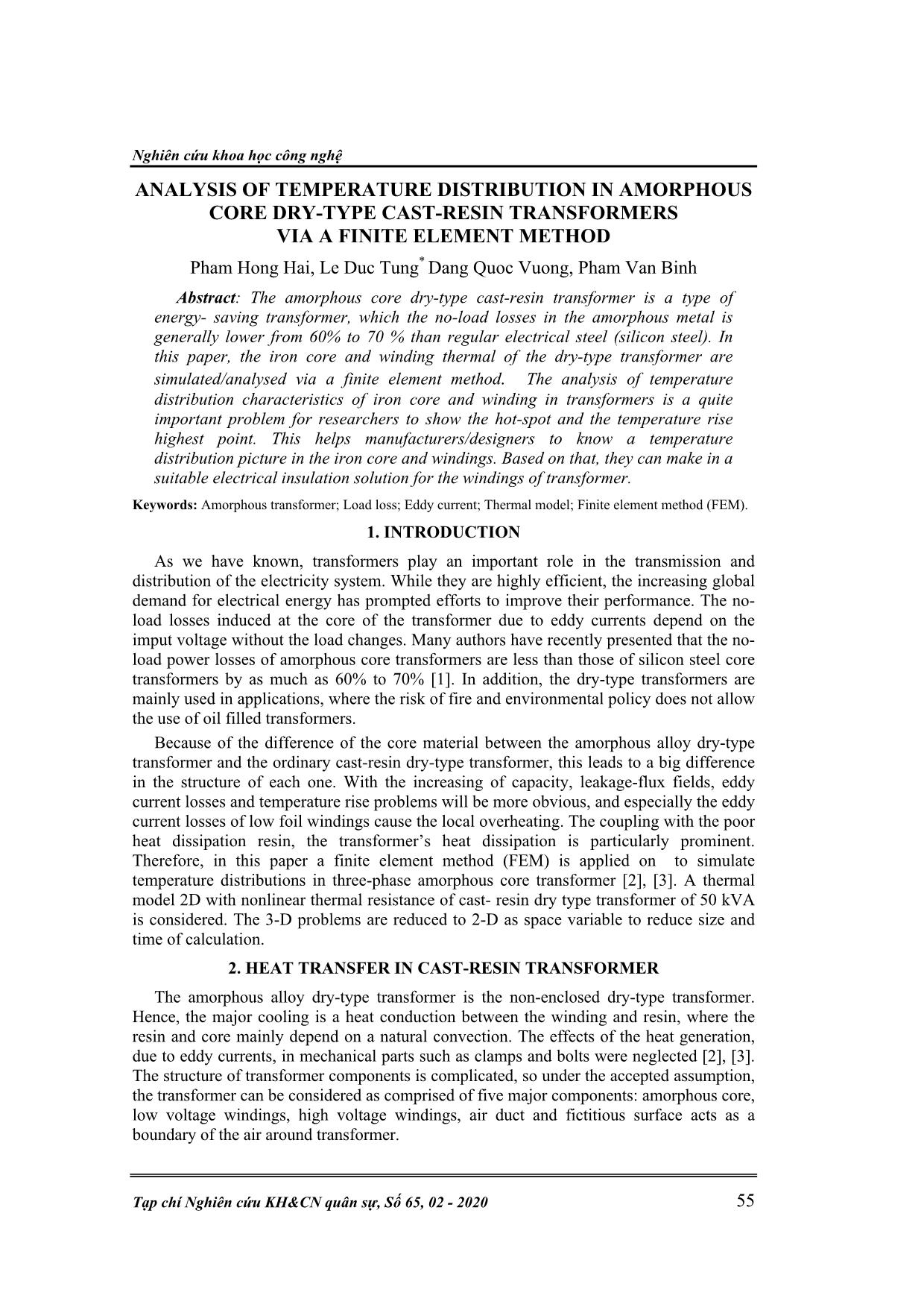
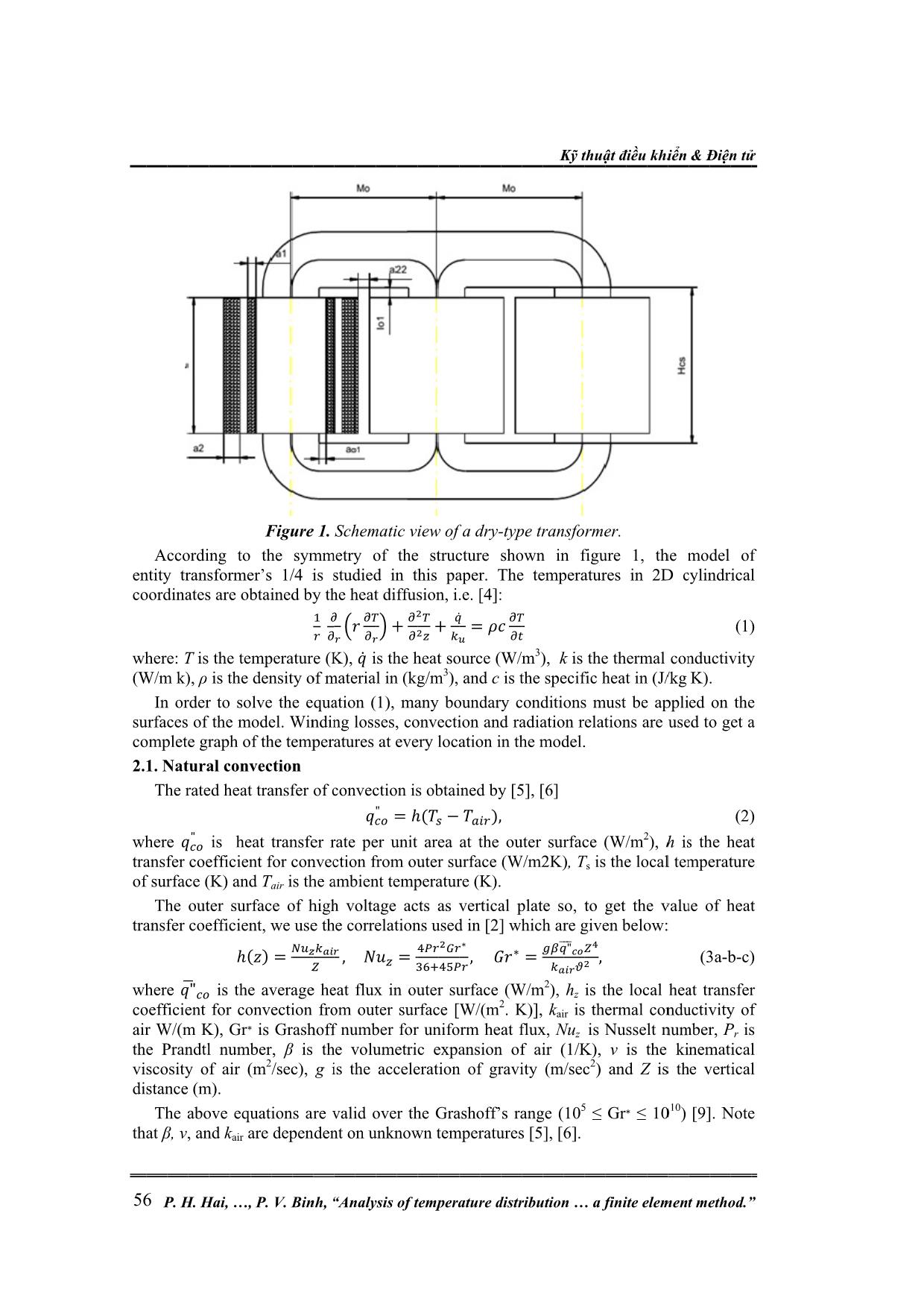
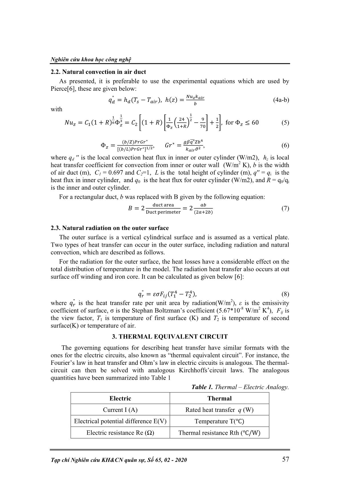
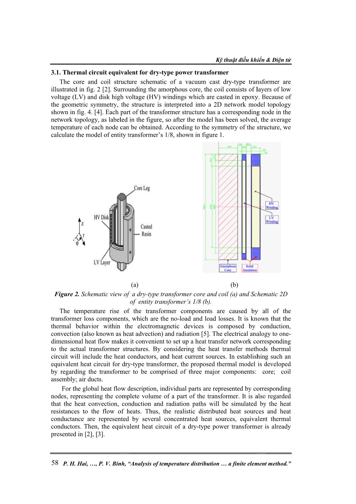
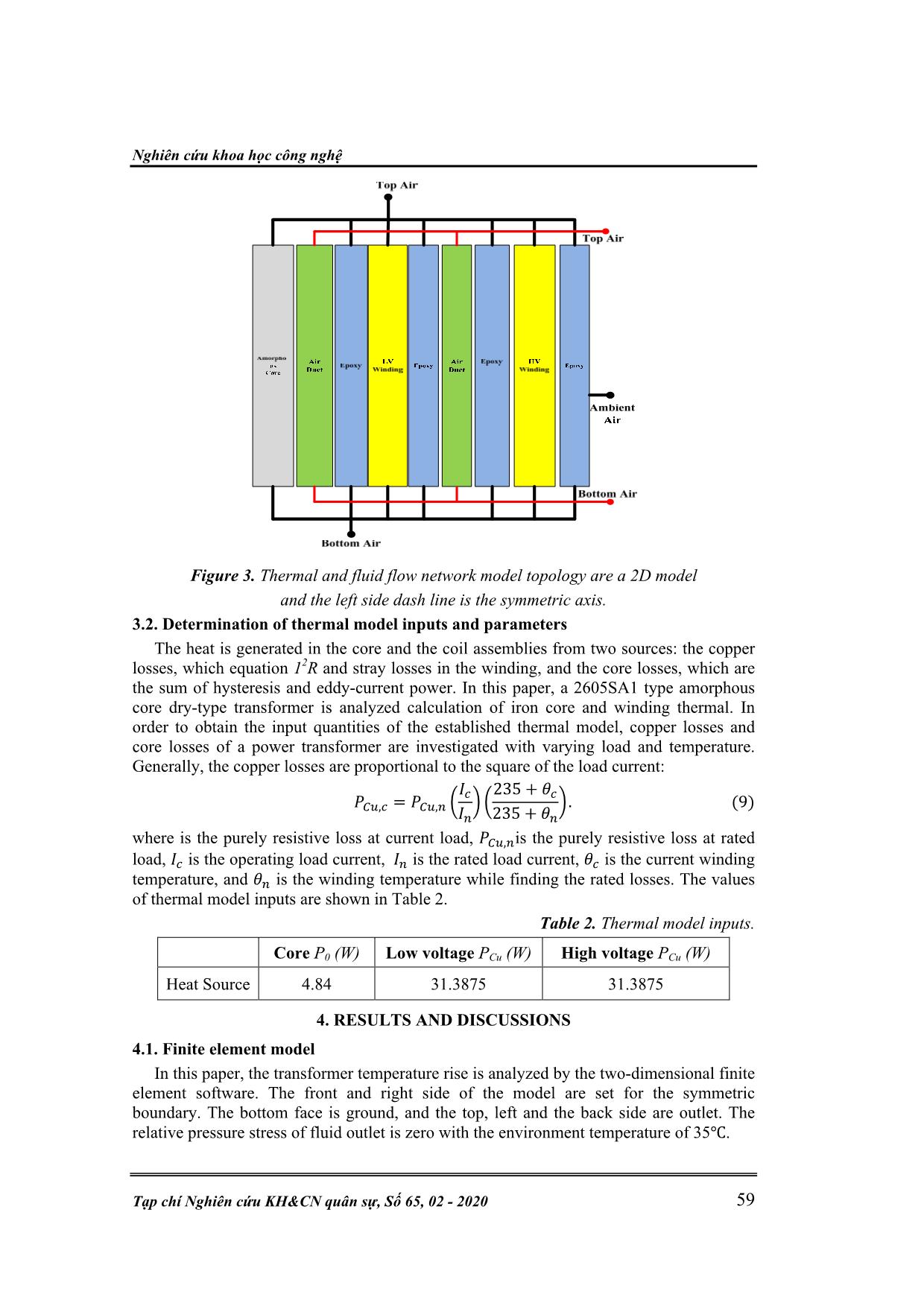
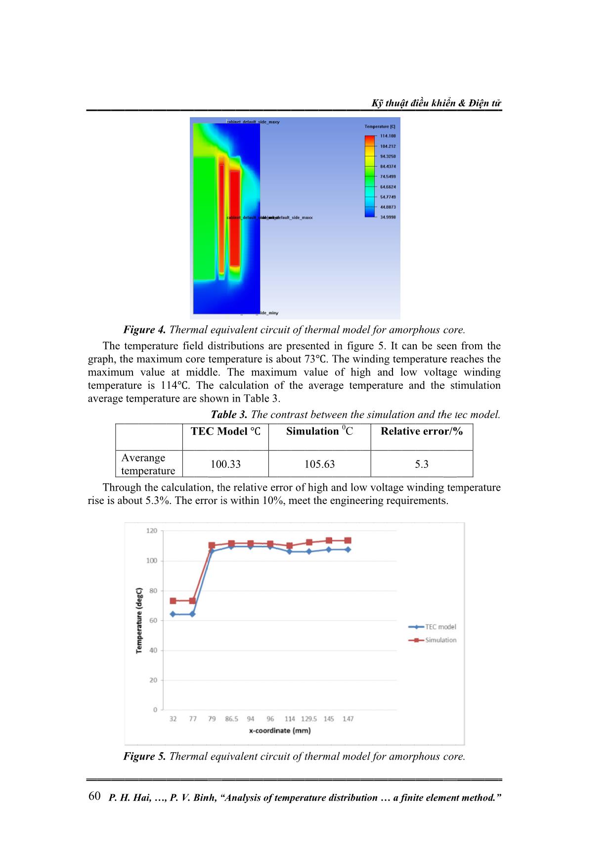
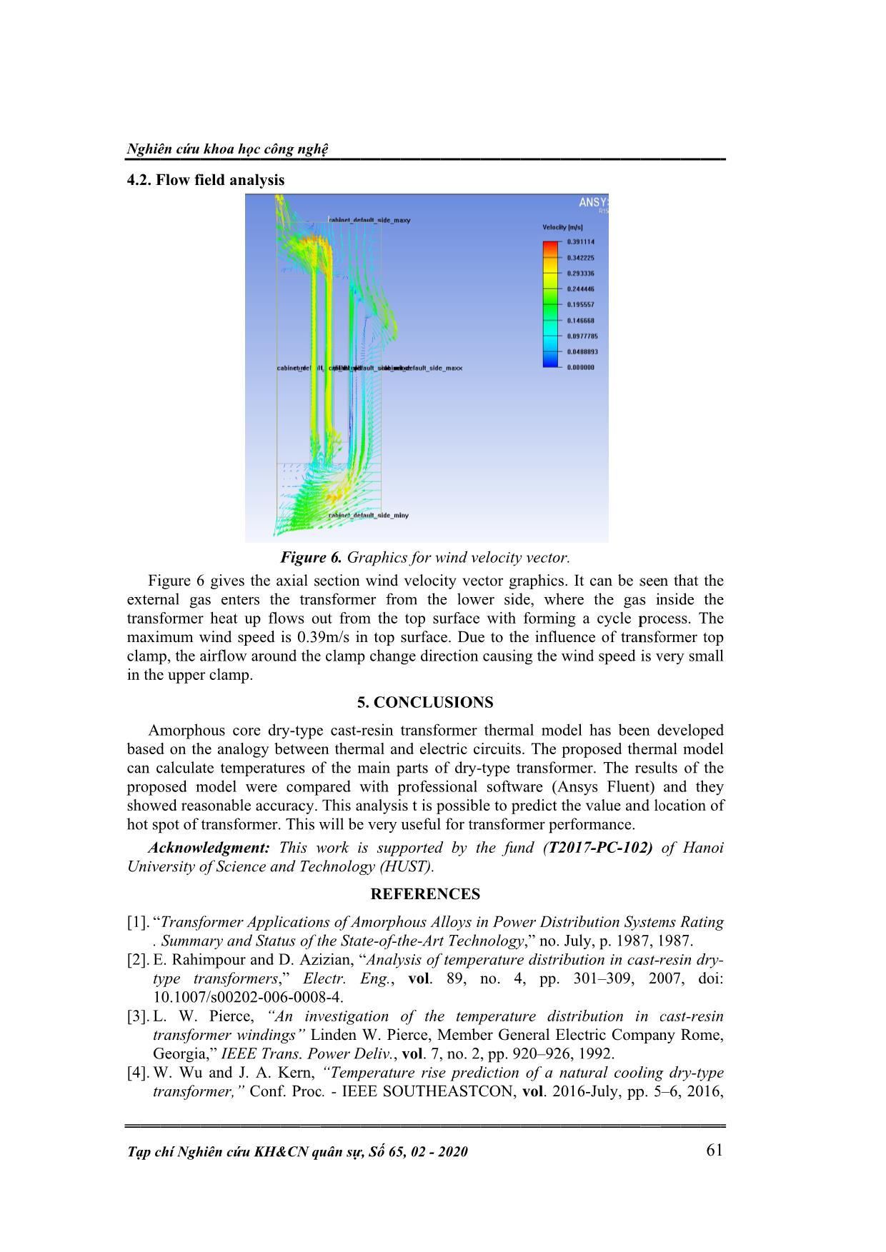
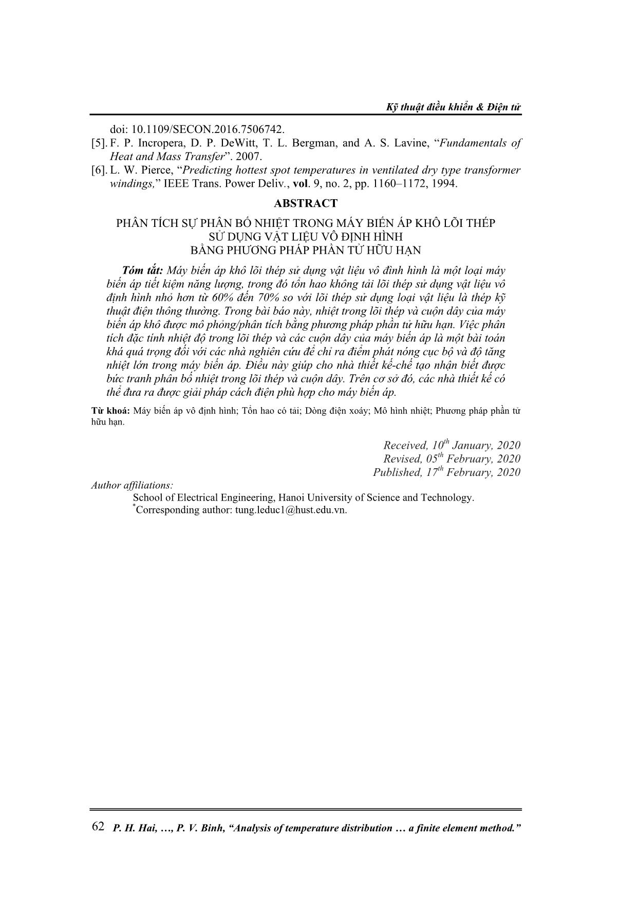
is the non-enclosed dry-type transformer. Hence, the major cooling is a heat conduction between the winding and resin, where the resin and core mainly depend on a natural convection. The effects of the heat generation, due to eddy currents, in mechanical parts such as clamps and bolts were neglected [2], [3]. The structure of transformer components is complicated, so under the accepted assumption, the transformer can be considered as comprised of five major components: amorphous core, low voltage windings, high voltage windings, air duct and fictitious surface acts as a boundary of the air around transformer. 56 entity transformer’s 1/4 coordinates are obtained by the heat diffusion where: (W/m k), surfaces of the model. Winding losses, convection and radiation relations are used to get a complete graph of the temperatures at every location i 2.1. where transfer coefficient for convection from outer surface (W/m2K) of surface (K) and transfer coefficient, we use the correlations used in where coefficient for convection from outer surface [W/(m air W/(m K), the Prandtl number, viscosity of air (m distance (m). that P According to the symmetry of the structure In order to solve the equation (1), many boundary conditions must be applied on the Natural convection The rated heat transfer of convection is obtained by The outer su The above equations are valid over the Grashoff’s range (10 β, ν . H T � �� , and . Hai, is the temperature (K), ρ �� " "�� is the density of material in (kg/m is heat transfer rate per unit area at the outer surface (W/m is the Gr k , P rface of high voltage acts as vertical plate so, to get the value of heat ℎ( ∗ air are dependent on unknown temperatures [5], [6]. . Figure 1. Tair �) average heat flux in outer surface (W/m is 2/sec), V. Binh is the = �� Grashoff number for uniform heat flux, β is studied in this paper � � � � is the volumetric expansion of air (1/K), , “ � � ambient temperature (K). ���� g is the acceleration of gravity (m/sec Analysis of temperature distribution Schematic view of a dry � �� , �� �� �̇ is the heat source (W/m ��� " �� � + ̇ = � �� �� ̇ ℎ = � �� � � + (�� �� � , i.e. �̇ �� 3), and − ��� ���� [4] ̇ = ���� ∗ , - shown in . The temperatures in 2D cylindrical : ̇ �� c ), [2] �� 2 type transformer �� �� is the s n the model. [5] which are given below: ∗ . K)], 3), , [6] = �� K k pecific heat in (J/kg K). �� ���� 2), kair Nu ỹ thuật điều f is the thermal conductivity , T "����� �� hz is the is z 5 a finite element method igure 1 s is the local temperature � , thermal conductivity of is Nusselt number, 2) and ≤ . ν is the kinematical Gr∗ , the model of 2 local heat transfer Z ≤ 10 khi ), h is the vertical ển & Điện tử is 10) [9]. Note the (3a heat -b P .” (1) (2) -c) r is Nghiên cứu khoa học công nghệ Tạp chí Nghiên cứu KH&CN quân sự, Số 65, 02 - 2020 57 2.2. Natural convection in air duct As presented, it is preferable to use the experimental equations which are used by Pierce[6], these are given below: �� " = ℎ�(�� − ����), ℎ(�) = ������� � (4a-b) with ��� = ��(1 + �) � �Φ� � � = �� �(1 + �) � � �� � �� ��� � � � − � �� � + � � �, for Φ� ≤ 60 (5) Φ� = (�/�)����∗ [(�/�)����∗]�/� , ��∗ = ���"������ ����� � , (6) where qd ′′ is the local convection heat flux in inner or outer cylinder (W/m2), hz is local heat transfer coefficient for convection from inner or outer wall (W/m2 K), b is the width of air duct (m), C1 = 0.697 and C2=1, L is the total height of cylinder (m), q′′ = qi is the heat flux in inner cylinder, and q0 is the heat flux for outer cylinder (W/m2), and R = q0/qi is the inner and outer cylinder. For a rectangular duct, b was replaced with B given by the following equation: � = 2 ���� ���� ���� ��������� = 2 �� (�����) (7) 2.3. Natural radiation on the outer surface The outer surface is a vertical cylindrical surface and is assumed as a vertical plate. Two types of heat transfer can occur in the outer surface, including radiation and natural convection, which are described as follows. For the radiation for the outer surface, the heat losses have a considerable effect on the total distribution of temperature in the model. The radiation heat transfer also occurs at out surface off winding and iron core. It can be calculated as given below [6]: �� " = �����(�� � − �� �), (8) where �� " is the heat transfer rate per unit area by radiation(W/m2), ε is the emissivity coefficient of surface, σ is the Stephan Boltzman’s coefficient (5.67*10-8 W/m2 K4), Fij is the view factor, T1 is temperature of first surface (K) and T2 is temperature of second surface(K) or temperature of air. 3. THERMAL EQUIVALENT CIRCUIT The governing equations for describing heat transfer have similar formats with the ones for the electric circuits, also known as “thermal equivalent circuit”. For instance, the Fourier’s law in heat transfer and Ohm’s law in electric circuits is analogous. The thermal- circuit can then be solved with analogous Kirchhoffs’circuit laws. The analogous quantities have been summarized into Table 1 Table 1. Thermal – Electric Analogy. Electric Thermal Current I (A) Rated heat transfer q (W) Electrical potential difference E(V) Temperature T(℃) Electric resistance Re (Ω) Thermal resistance Rth (℃/W) 58 3.1. illustrated in voltage (LV) and disk the geometric symmetry, the structure is interpreted into a 2D network model topology shown in network topology, as labeled in the figure temperature of each node can be obtained. According to the symmetry of the structure, we calculate the model of entity transformer’s 1/8, shown in Figure 2. transformer loss components, which are the no thermal behavior within the electromagnetic devices is composed by conduction, convection (also known as heat advection) and radiation dimensional heat flow makes it convenient to set up a heat transfer network corresponding to the actual transformer structures. By consi circuit will include the heat conductors, and heat current sources. In establishing such an equivalent heat circuit for dry by regarding the transformer to b assembly; air ducts. nodes, representing the complete volume of a part of the transformer. It is also regarded that resistances to the flow of heats. Thus, the realistic distributed heat sources and heat conductance are represented by several concentrated heat sources, equivalent thermal conductors. Then, the equivalent heat circuit of a dry presented P Thermal circuit The core and coil structure schematic of a vacuum cast dry The temperature rise of the transformer components are caused by all of the For the global heat flow description, individual parts are represented by corresponding the heat convection, conduction and radiation paths will be simulated by the heat . H. Hai, fig. 4. in [2], [3]. fig. 2 Schematic view of a dry , P [4] . [2] . Each part of the transformer structure has a corresponding node in the V. Binh equivalent for dry . Surrounding the amorphous core, the coil consists of layers of low high voltage (HV) windings which are casted in epoxy. Because of , “Analysis of temperature distribution (a) of entity transformer’s 1/8 -type transformer, the proposed thermal model is developed e comprised of three major components: core -type transformer core and coil - type power transformer , so after the model has been solved, the -load and loa dering the heat transfer methods thermal -type power transformer is already figure 1. (b). [5]. The electrical analogy to one K d losses. It is known that the ỹ thuật điều a finite element method - (b) (a) type transformer are and Schematic 2D khiển & Điện tử average ; coil .” - Nghiên cứu khoa học công nghệ Tạp chí Nghiên cứu KH&CN quân sự, Số 65, 02 - 2020 59 Figure 3. Thermal and fluid flow network model topology are a 2D model and the left side dash line is the symmetric axis. 3.2. Determination of thermal model inputs and parameters The heat is generated in the core and the coil assemblies from two sources: the copper losses, which equation 12R and stray losses in the winding, and the core losses, which are the sum of hysteresis and eddy-current power. In this paper, a 2605SA1 type amorphous core dry-type transformer is analyzed calculation of iron core and winding thermal. In order to obtain the input quantities of the established thermal model, copper losses and core losses of a power transformer are investigated with varying load and temperature. Generally, the copper losses are proportional to the square of the load current: ���,� = ���,� � �� �� � � 235 + �� 235 + �� �. (9) where is the purely resistive loss at current load, ���,�is the purely resistive loss at rated load, �� is the operating load current, �� is the rated load current, �� is the current winding temperature, and �� is the winding temperature while finding the rated losses. The values of thermal model inputs are shown in Table 2. Table 2. Thermal model inputs. Core P0 (W) Low voltage PCu (W) High voltage PCu (W) Heat Source 4.84 31.3875 31.3875 4. RESULTS AND DISCUSSIONS 4.1. Finite element model In this paper, the transformer temperature rise is analyzed by the two-dimensional finite element software. The front and right side of the model are set for the symmetric boundary. The bottom face is ground, and the top, left and the back side are outlet. The relative pressure stress of fluid outlet is zero with the environment temperature of 35℃. 60 graph, the maximum core temperature is about 73 maximum value at middle. The maximum value of high and low voltage winding temperature is 114 average rise is about 5.3%. The error is within 10%, meet the engineering requirements. P The temperature field distributions are presented in Through the calculation, the relative error of high and low voltage . H Figure 4. Averange temperature Figure 5. . Hai, temperature are shown in Table , P. Thermal equivalent circuit of thermal model for amorphous core. ℃ Thermal equivalent circuit of thermal model for amorphous core. V. Binh . The calculation of the average temperature and the stimulation TEC Model , “ Table 3. 100.33 Analysis of temperature distribution The contrast between the simulation and the tec model. ℃ 3. Simulation 105.63 ℃. The winding temperature reaches the 0C figure 5. It can be seen from Kỹ thuật điều Relative error/% a finite element method 5.3 winding temperature khiển & Điện tử .” the Nghiên c Tạp chí Nghi 4.2. Flow field analysis external gas enters the transformer from the lower side, where the gas inside the transformer heat up flows out from the top surface with forming a cycle process. The maximum clamp, the airflow around the clamp change direction causing the wind speed is very small in the upper clamp. based on the analogy between thermal and electric circuits. The proposed thermal model can calculate temperatures of the main parts of dry proposed model were compared with professional softwa showed reasonable accuracy. This analysis t is possible to predict the value and location of hot spot of transformer. This will be very useful for transformer performance. University of Science and Technology (HUST). [1] [2] [3] [4] Figure Amorphous core dry Acknowledgment: . “Transformer Applications of Amorphous Alloys in Power Distribution Systems Rating . Summary and Status of the State . E. Rahimpour and D. Azizian, “ type transformers 10.1007/s00202 . L. W. Pierce, transformer windings” Georgia,” . W. Wu and J. A. Kern, transformer,” ứu khoa học công nghệ 6 wind speed is 0.39m/s in top surface. Due to the influence of transformer top ên c gives the axial section wind velocity vector graphics. It can be seen that the ứu KH&CN IEEE Trans. Power Deliv. - Conf. Proc Figure 6. This work is supported by the fund ( ,” 006 “An inv -type cast -0008 quân s Electr. Eng. Linden W. Pierce, Member General Electric Company Rome, -4. estigation of the temperature distribution in cast “Temperature rise predic . - ự, Số Graphics for wind velocity vector. 5 - IEEE SOUTHEASTCON . CONCLUSIONS resin transformer therma REFERENCES -of Analysis of temperature distribution in cast 65 -the , , , 02 - vol vol - 20 Art . 89, no. 4, pp. 301 . 7, no. 2, pp. 920 20 Technology - type transformer. The results of the tion of a natural cooling dry , l model has been developed re (Ansys Fluent) and they ,” no. July, p. 1987, 1987. – vol T2017 926, 1992. . 2016 -PC – -July, pp. 5 - 309, 2007, doi: 102) -resin dry of Hanoi –6, 2016, -resin -type 61 - Kỹ thuật điều khiển & Điện tử P. H. Hai, , P. V. Binh, “Analysis of temperature distribution a finite element method.” 62 doi: 10.1109/SECON.2016.7506742. [5]. F. P. Incropera, D. P. DeWitt, T. L. Bergman, and A. S. Lavine, “Fundamentals of Heat and Mass Transfer”. 2007. [6]. L. W. Pierce, “Predicting hottest spot temperatures in ventilated dry type transformer windings,” IEEE Trans. Power Deliv., vol. 9, no. 2, pp. 1160–1172, 1994. ABSTRACT PHÂN TÍCH SỰ PHÂN BỐ NHIỆT TRONG MÁY BIẾN ÁP KHÔ LÕI THÉP SỬ DỤNG VẬT LIỆU VÔ ĐỊNH HÌNH BẰNG PHƯƠNG PHÁP PHẦN TỬ HỮU HẠN Tóm tắt: Máy biến áp khô lõi thép sử dụng vật liệu vô đình hình là một loại máy biến áp tiết kiệm năng lượng, trong đó tổn hao không tải lõi thép sử dụng vật liệu vô định hình nhỏ hơn từ 60% đến 70% so với lõi thép sử dụng loại vật liệu là thép kỹ thuật điện thông thường. Trong bài báo này, nhiệt trong lõi thép và cuộn dây của máy biến áp khô được mô phỏng/phân tích bằng phương pháp phần tử hữu hạn. Việc phân tích đặc tính nhiệt độ trong lõi thép và các cuộn dây của máy biến áp là một bài toán khá quá trọng đối với các nhà nghiên cứu để chỉ ra điểm phát nóng cục bộ và độ tăng nhiệt lớn trong máy biến áp. Điều này giúp cho nhà thiết kế-chế tạo nhận biết được bức tranh phân bố nhiệt trong lõi thép và cuộn dây. Trên cơ sở đó, các nhà thiết kế có thể đưa ra được giải pháp cách điện phù hợp cho máy biến áp. Từ khoá: Máy biến áp vô định hình; Tổn hao có tải; Dòng điện xoáy; Mô hình nhiệt; Phương pháp phần tử hữu hạn. Received, 10th January, 2020 Revised, 05th February, 2020 Published, 17th February, 2020 Author affiliations: School of Electrical Engineering, Hanoi University of Science and Technology. *Corresponding author: tung.leduc1@hust.edu.vn.
File đính kèm:
 analysis_of_temperature_distribution_in_amorphous_core_dry_t.pdf

