A force measuring microsystem bases on electrothermal v-shaped actuator
This paper describes design and calculation of an electrothermal V-shaped actuator (EVA) and an amplification mechanism integrated into a force measuring microsystem (FMMS), aims to apply for characterization of a micro beam. Displacement and driving force are generated by thermal expansion of the V-shaped silicon beams while applying a voltage to the electrodes of the EVA. ANSYS simulation helps to find out the relations
between thermal force and displacement corresponding to driving voltage and determine
the temperature of V-shaped beam at various applying voltages. In our simulation, with
applying voltage Um = 38 volt for six pairs of V-shaped beam, the maximal temperature
of the beam reaches approximately to 1100°C and causes a melting phenomenon of the
silicon beam. The additional amplification mechanism allows actuator’s displacement to
be 6 times larger than before the improvement, thus the bending deformation of the micro beam can be seen perfectly, i.e. the force loading on the beam can be computed more
exactly via a measured displacement of the beam tip. In addition, this FMMS has smaller
size and supplies a larger beam’s deformation at the same voltage in comparison with
previous design
Trang 1
Trang 2
Trang 3
Trang 4
Trang 5
Trang 6
Trang 7
Trang 8
Tóm tắt nội dung tài liệu: A force measuring microsystem bases on electrothermal v-shaped actuator
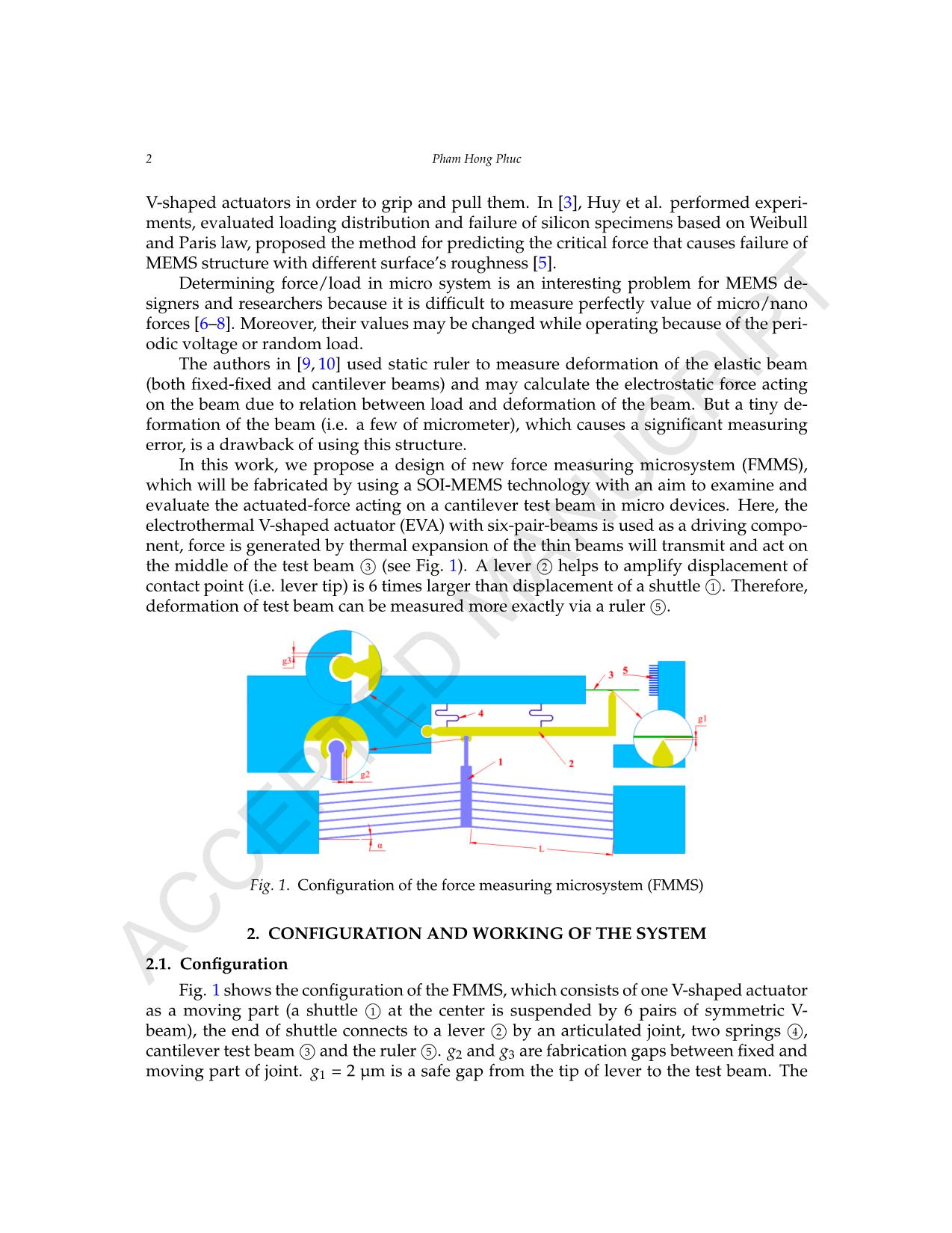
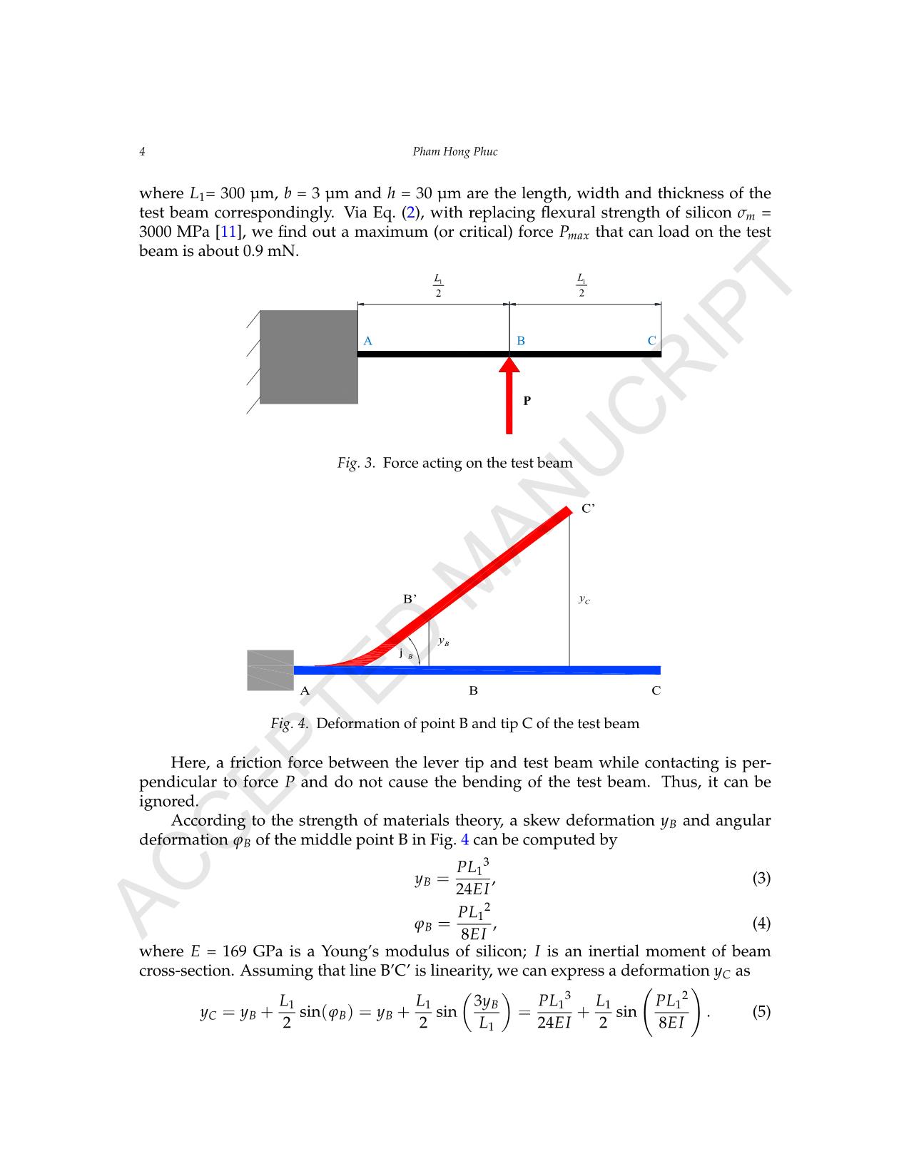
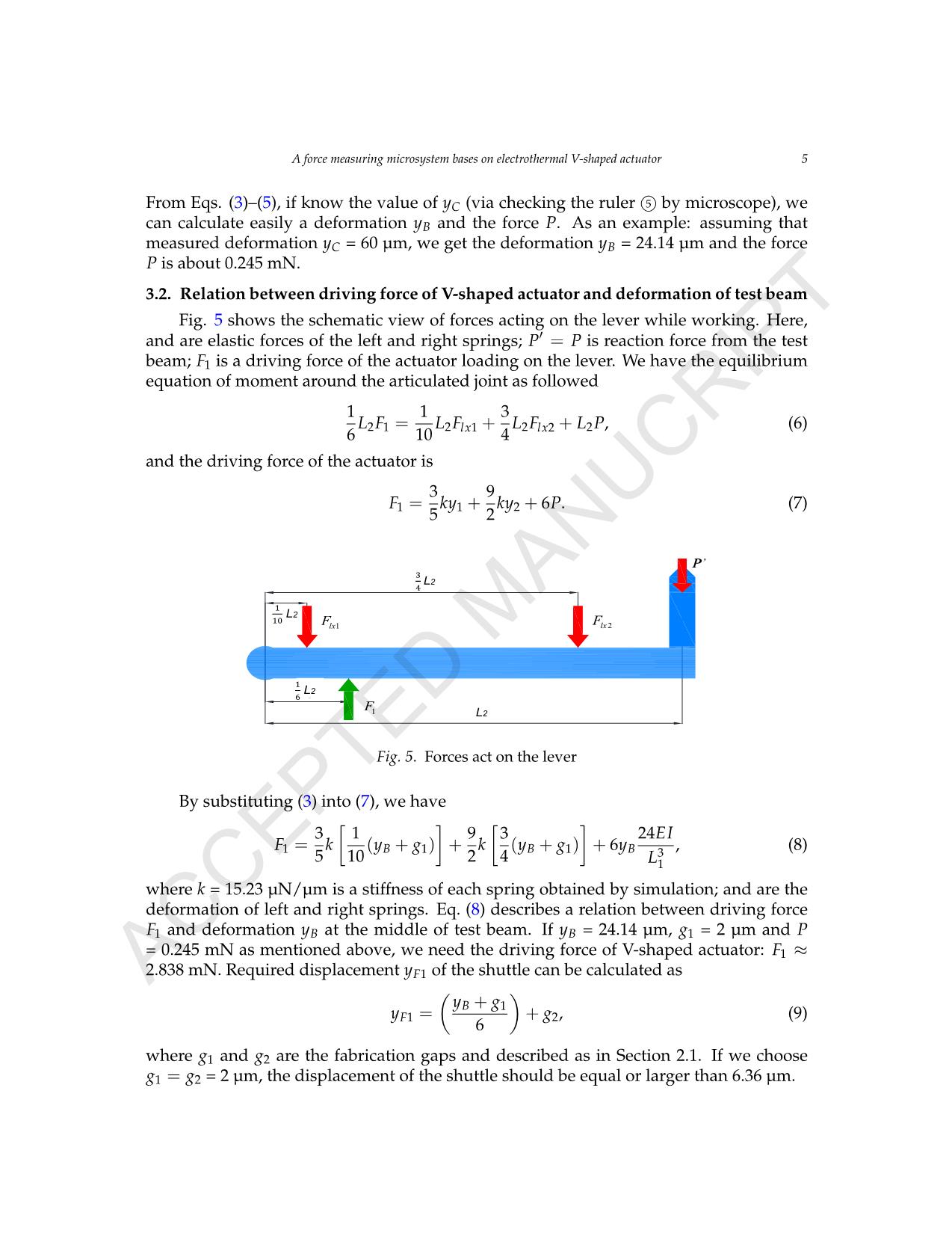
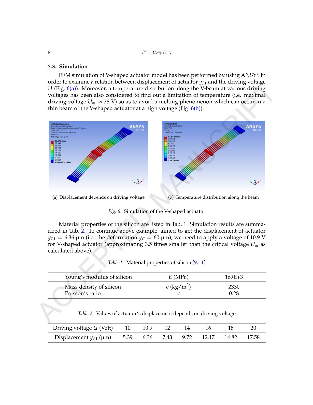
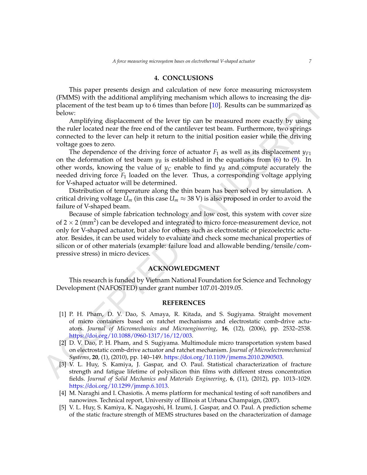
2 max 1 . . 3 h b P L s = P 1 2 L 1 2 L B CA Bj By Cy A B C B’ C’ Fig. 4. Deformation of point B and tip C of the test beam Here, a friction force between the lever tip and test beam while contacting is per- pendicular to force P and do not cause the bending of the test beam. Thus, it can be ignored. According to the strength of materials theory, a skew deformation yB and angular deformation ϕB of the middle point B in Fig. 4 can be computed by yB = PL13 24EI , (3) ϕB = PL12 8EI , (4) where E = 169 GPa is a Young’s modulus of silicon; I is an inertial moment of beam cross-section. Assuming that line B’C’ is linearity, we can express a deformation yC as yC = yB + L1 2 sin(ϕB) = yB + L1 2 sin ( 3yB L1 ) = PL13 24EI + L1 2 sin ( PL12 8EI ) . (5) AC CE PT ED M AN UC RI PT A force measuring microsystem bases on electrothermal V-shaped actuator 5 From Eqs. (3)–(5), if know the value of yC (via checking the ruler 5© by microscope), we can calculate easily a deformation yB and the force P. As an example: assuming that measured deformation yC = 60 µm, we get the deformation yB = 24.14 µm and the force P is about 0.245 mN. 3.2. Relation between driving force of V-shaped actuator and deformation of test beam Fig. 5 shows the schematic view of forces acting on the lever while working. Here, and are elastic forces of the left and right springs; P′ = P is reaction force from the test beam; F1 is a driving force of the actuator loading on the lever. We have the equilibrium equation of moment around the articulated joint as followed 1 6 L2F1 = 1 10 L2Flx1 + 3 4 L2Flx2 + L2P, (6) and the driving force of the actuator is F1 = 3 5 ky1 + 9 2 ky2 + 6P. (7) 4 Pham Hong Phuc Here, a friction force between the lever tip and test beam while contacting is perpendicular to force P and do not cause the bending of the test beam. Thus, it can be ignored. According to the strength of materials theory, a skew deformation yB and angular deformation φB of the middle point B in Fig. 4 can be computed by: (3) (4) Where E = 169 GPa is a Young’s modulus f silicon; I = is an inertial moment of beam c oss- section. Assuming that line B’C’ is linearity, we can express a deformation yC as: (5) From equations (3-5), if know the value of yC (via checking the ruler by microscope), we can calculate easily a deformation yB and the force P. As an example: assuming that measured deformation yC = 60 µm, we get the deformation yB = 24.14 µm and the force P is about 0.245 mN. 3.2. Relation between driving force of V-shaped actuator and deformation of test beam Fig. 5. Forces act on the lever Fig. 5 shows the schematic view of forces acting on the lever while working. Here, and are elastic forces of the left and right springs; P’=P is reaction force from the test beam; F1 is a driving force of the actuator loading on the lever. We have the equilibrium equation of moment around the articulated joint as followed: (6) And the driving force of the actuator is: (7) By substituting (3) into (7), we have: (8) 3 1. 24 .B P Ly E I = 2 1. 8 .B P L E I j = 3. 12 h b 3 2 1 1 1 1 1 1 3. . ..sin( ) .sin .sin 2 2 24 . 2 8 . B C B B B L L y P L L P Ly y y L E I E I j Ê ˆÊ ˆ ˜˜ ÁÁ ˜˜= + = + = + ÁÁ ˜˜ ÁÁ ˜˜Á ÁË ¯ Ë ¯ 1L 1 6 L 1 10 L 1 3 4 L 1lxF 2lxF P 1F L2 L2 L2 L2 ’ 1 1.lxF k y= 2 2.lxF k y= 2 1 2 1 2 2 2 1 1 3. . . . 6 10 4lx lx L F L F L F L P= + + 1 1 2 3 9. . 6 5 2 F k y k y P= + + 1 1 1 3 1 3 1 9 3 24 .. ( ) . ( ) 6 . 5 10 2 4B B B E IF k y g k y g y L È ˘ È ˘ Í ˙ Í ˙= + + + +Í ˙ Í ˙Î ˚ Î ˚ Fig. 5. Forces act on the lever By substituting (3) into (7), we have F1 = 3 5 k [ 1 10 (yB + g1) ] + 9 2 k [ 3 4 (yB + g1) ] + 6yB 24EI L31 , (8) where k = 15.23 µN/µm is a stiffness of each spring obtained by simulation; and are the deformation of left and right springs. Eq. (8) describes a relation between driving force F1 and deformation yB at the middle of test beam. If yB = 24.14 µm, g1 = 2 µm and P = 0.245 mN as mentioned above, we need the driving force of V-shaped actuator: F1 ≈ 2.838 mN. Required displacement yF1 of the shuttle can be calculated as yF1 = ( yB + g1 6 ) + g2, (9) where g1 and g2 are the fabrication gaps and described as in Section 2.1. If we choose g1 = g2 = 2 µm, the displacement of the shuttle should be equal or larger than 6.36 µm. AC CE PT ED M AN UC RI PT 6 Pham Hong Phuc 3.3. Simulation FEM simulation of V-shaped actuator model has been performed by using ANSYS in order to examine a relation between displacement of actuator yF1 and the driving voltage U (Fig. 6(a)). Moreover, a temperature distribution along the V-beam at various driving voltages has been also considered to find out a limitation of temperature (i.e. maximal driving voltage Um ≈ 38 V) so as to avoid a melting phenomenon which can occur in a thin beam of the V-shaped actuator at a high voltage (Fig. 6(b)). A Force Measuring Microsystem Bases on the Electrothermal V-shaped Actuator 5 Where k = 15.23 µN/µm is a stiffness of each spring obtained by simulation; and are the deformation of left and right springs. Equation (8) describes a relation between driving force F1 and deformation yB at the middle of test beam. If yB = 24.14 µm, g1 = 2 µm and P = 0.245 mN as mentioned above, we need the driving force of V-shaped actuator: F1 ≈ 2.838 mN. Required displacement yF1 of the shuttle can be calculated as: (9) Where g1 and g2 are the fabrication gaps and described as in the section 2.1. If we choose g1 = g2 = 2µm, the displacement of the shuttle should be equal or larger than 6.36 µm. 3.3. Simulation FEM simulation f V-shaped actuator model has een perf rmed by using ANSYS in order to ex- amine a relation betw en displa ement of actuator yF1 and the driving voltage U (Fig. 6a). Moreover, a temperature distribution along the -beam at various driving voltages has been also considered to find out a limitation of temperature (i.e. maximal driving voltage Um ≈ 38V ) so as to avoid a melting phe- nomenon which can occur in a thin beam of the V-shaped actuator at a high voltage (Fig. 6b). (a) Displacement depends on driving voltage; (b) Temperature distribution along the beam; Fig. 6. Simulation of the V-shaped actuator Material properties of the silicon are listed in Table 1. Simulation results are summarized in Table 2. To continue above example, aimed to get the displacement of actuator yF1 = 6.36 µm (i.e. the deformation yC = 60 µm), we need to apply a voltage of 10.9 V for V-shaped actuator (approximating 3.5 times smaller than the critical voltage Um as calculated above). Table 1. Material properties of silicon [8, 10] Young’s modulus of silicon E (MPa) 169E+3 Mass density of silicon ρ (kg/m3) 2330 Poisson’s ratio υ 0.28 Table 2. Values of actuator’s displacement depends on driving voltage Driving voltage U (Volt) 10 10.9 12 14 16 18 20 Displacement yF1 (µm) 5.39 6.36 7.43 9.72 12.17 14.82 17.58 1 1 1 ( ) 10 B y y g= + 2 1 3 ( ) 4 B y y g= + 1 1 26 B F y gy g Ê ˆ+ ˜Á= +˜Á ˜˜ÁË ¯ (a) Displacement depends on driving voltage A Force Measuring Microsystem Bases on the Electrothermal V-shaped Actuator 5 Where k = 15.23 µN/µm is a stiffness of each spring obtained by simulation; and are the deformation of left and right springs. Equation (8) describes a relation between driving force F1 and deformation yB at the middle of test beam. If yB = 24.14 µm, g1 = 2 µm and P = 0.245 mN as mentioned above, we need the driving force of V-shaped actuator: F1 ≈ 2.838 mN. Required displacement yF1 of the shuttle can be calculated as: (9) Where g1 and g2 are the fabrication gaps and described as in the section 2.1. If we choose g1 = g2 = 2µm, the displacement of the shuttle should be equal or larger than 6.36 µm. 3.3. Simulation FEM simulation of V-sh p d actu or model has been perform d by using ANSYS in order to ex- amine a relation between displacement of actuator yF1 nd the driving voltage U (Fig. 6a). Moreover, a temperature distribution along the V-beam t various driving voltages has been also considered to find out a limitation of temperatur (i.e. maximal driving voltag Um ≈ 38V ) so as to avoid a melting phe- nome on which can occur in a thin beam of the V-shaped actuator at a igh voltage (Fig. 6b). (a) Displac ment depends on driving voltage; (b) Temperature distribution along the beam; Fig. 6. Simulation of the V-shaped actuator Material properties of the silicon are listed in Table 1. Simulation results are summarized in Table 2. To continue above example, aimed to get the displacement of actuator yF1 = 6.36 µm (i.e. the deformation yC = 60 µm), we need to apply a voltage of 10.9 V for V-shaped actuator (approximating 3.5 times smaller than the critical voltage Um as calculated above). Table 1. Material properties of silicon [8, 10] Young’s modulus of silicon E (MPa) 169E+3 Mass density of silicon ρ (kg/m3) 2330 Poisson’s ratio υ 0.28 Table 2. Values of actuator’s displacement depends on driving voltage Driving voltage U (Volt) 10 10.9 12 14 16 18 20 Displacement yF1 (µm) 5.39 6.36 7.43 9.72 12.17 14.82 17.58 1 1 1 ( ) 10 B y y g= + 2 1 3 ( ) 4 B y y g= + 1 1 26 B F y gy g Ê ˆ+ ˜Á= +˜Á ˜˜ÁË ¯ (b) Temperature distribution along the beam Fig. 6. Simulation of the V-shaped actuator Material properti s of the silicon are liste in Tab. 1. Simul ti n results are su ma- rized i Tab. 2. To continue above exampl , aimed to get the displacement of actu or yF1 = 6.36 µm (i.e. the deformation yC = 60 µm), we need to apply a voltage of 10.9 V for V-shaped actuator (approximating 3.5 times smaller than the critical voltage Um as calculated above). Table 1. Material properties of silicon [9, 11] Young’s modulus of silicon E (MPa) 169E+3 Mass density of silicon ρ (kg/m3) 2330 Poisson’s ratio ν 0.28 Table 2. Values of actuator’s displacement depends on driving voltage Driving voltage U (Volt) 10 10.9 12 14 16 18 20 Displacement yF1 (µm) 5.39 6.36 7.43 9.72 12.17 14.82 17.58 AC CE PT ED MA NU CR IP T A force measuring microsystem bases on electrothermal V-shaped actuator 7 4. CONCLUSIONS This paper presents design and calculation of new force measuring microsystem (FMMS) with the additional amplifying mechanism which allows to increasing the dis- placement of the test beam up to 6 times than before [10]. Results can be summarized as below: Amplifying displacement of the lever tip can be measured more exactly by using the ruler located near the free end of the cantilever test beam. Furthermore, two springs connected to the lever can help it return to the initial position easier while the driving voltage goes to zero. The dependence of the driving force of actuator F1 as well as its displacement yF1 on the deformation of test beam yB is established in the equations from (6) to (9). In other words, knowing the value of yC enable to find yB and compute accurately the needed driving force F1 loaded on the lever. Thus, a corresponding voltage applying for V-shaped actuator will be determined. Distribution of temperature along the thin beam has been solved by simulation. A critical driving voltage Um (in this case Um ≈ 38 V) is also proposed in order to avoid the failure of V-shaped beam. Because of simple fabrication technology and low cost, this system with cover size of 2× 2 (mm2) can be developed and integrated to micro force-measurement device, not only for V-shaped actuator, but also for others such as electrostatic or piezoelectric actu- ator. Besides, it can be used widely to evaluate and check some mechanical properties of silicon or of other materials (example: failure load and allowable bending/tensile/com- pressive stress) in micro devices. ACKNOWLEDGMENT This research is funded by Vietnam National Foundation for Science and Technology Development (NAFOSTED) under grant number 107.01-2019.05. REFERENCES [1] P. H. Pham, D. V. Dao, S. Amaya, R. Kitada, and S. Sugiyama. Straight movement of micro containers based on ratchet mechanisms and electrostatic comb-drive actu- ators. Journal of Micromechanics and Microengineering, 16, (12), (2006), pp. 2532–2538. https://doi.org/10.1088/0960-1317/16/12/003. [2] D. V. Dao, P. H. Pham, and S. Sugiyama. Multimodule micro transportation system based on electrostatic comb-drive actuator and ratchet mechanism. Journal of Microelectromechanical Systems, 20, (1), (2010), pp. 140–149. https://doi.org/10.1109/jmems.2010.2090503. [3] V. L. Huy, S. Kamiya, J. Gaspar, and O. Paul. Statistical characterization of fracture strength and fatigue lifetime of polysilicon thin films with different stress concentration fields. Journal of Solid Mechanics and Materials Engineering, 6, (11), (2012), pp. 1013–1029. https://doi.org/10.1299/jmmp.6.1013. [4] M. Naraghi and I. Chasiotis. A mems platform for mechanical testing of soft nanofibers and nanowires. Technical report, University of Illinois at Urbana Champaign, (2007). [5] V. L. Huy, S. Kamiya, K. Nagayoshi, H. Izumi, J. Gaspar, and O. Paul. A prediction scheme of the static fracture strength of MEMS structures based on the characterization of damage AC CE PT ED M AN UC RI PT 8 Pham Hong Phuc distribution on a processed surface. Journal of Micromechanics and Microengineering, 23, (4), (2013). https://doi.org/10.1088/0960-1317/23/4/045008. [6] H. Conrad, H. Schenk, B. Kaiser, S. Langa, M. Gaudet, K. Schimmanz, M. Stolz, and M. Lenz. A small-gap electrostatic micro-actuator for large deflections. Nature Communications, 6, (1), (2015), pp. 1–7. https://doi.org/10.1038/ncomms10078. [7] A. M. Ousaid, S. Haliyo, S. Re´gnier, and V. Hayward. Micro-force sensor by active control of a comb-drive. In 2013 IEEE/ASME International Conference on Advanced Intelligent Mechatronics, IEEE, (2013), pp. 612–617. https://doi.org/10.1109/aim.2013.6584160. [8] P. H. Phuc, D. K. Toan, D. B. Lam, N. T. Khoa, and N. T. Dung. Design and fabrication of the trapezoidal electrostatic comb-drive actuator. Vietnam Journal of Mechanics, 34, (4), (2012), pp. 261–269. https://doi.org/10.15625/0866-7136/34/4/2338. [9] P. H. Pham, T. K. Dinh, L. B. Dang, K. T. Nguyen, and D. V. Dao. Micro cam system driven by electrostatic comb-drive actuators based on SOI-MEMS technology. Microsystem Technologies, 21, (3), (2015), pp. 699–706. https://doi.org/10.1007/s00542-014-2086-y. [10] P. H. Pham, K. T. Nguyen, and L. B. Dang. Design and performance of a high loading electrostatic micro linear motor. Microsystem Technologies, 21, (11), (2015), pp. 2469–2474. https://doi.org/10.1007/s00542-014-2392-4. [11] J. J. Allen. MEMS design. Taylor & Francis Group, LLC, (2005). AC CE PT ED M AN UC RI PT
File đính kèm:
 a_force_measuring_microsystem_bases_on_electrothermal_v_shap.pdf

