A finite element method for modeling of electromagnetic problems
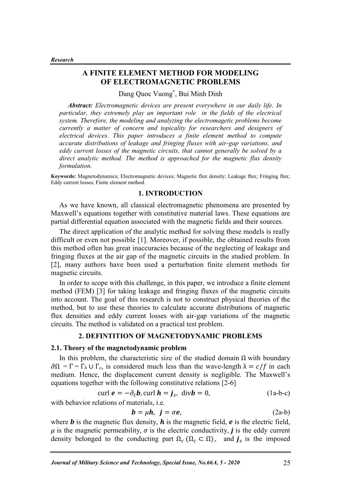
As we have known, all classical electromagnetic phenomena are presented by
Maxwell’s equations together with constitutive material laws. These equations are
partial differential equation associated with the magnetic fields and their sources.
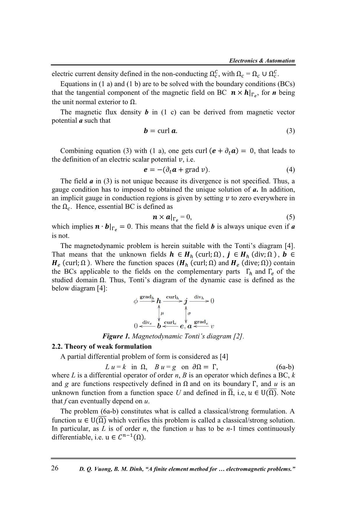
The direct application of the analytic method for solving these models is really
difficult or even not possible [1]. Moreover, if possible, the obtained results from
this method often has great inaccuracies because of the neglecting of leakage and
fringing fluxes at the air gap of the magnetic circuits in the studied problem. In
[2], many authors have been used a perturbation finite element methods for
magnetic circuits.
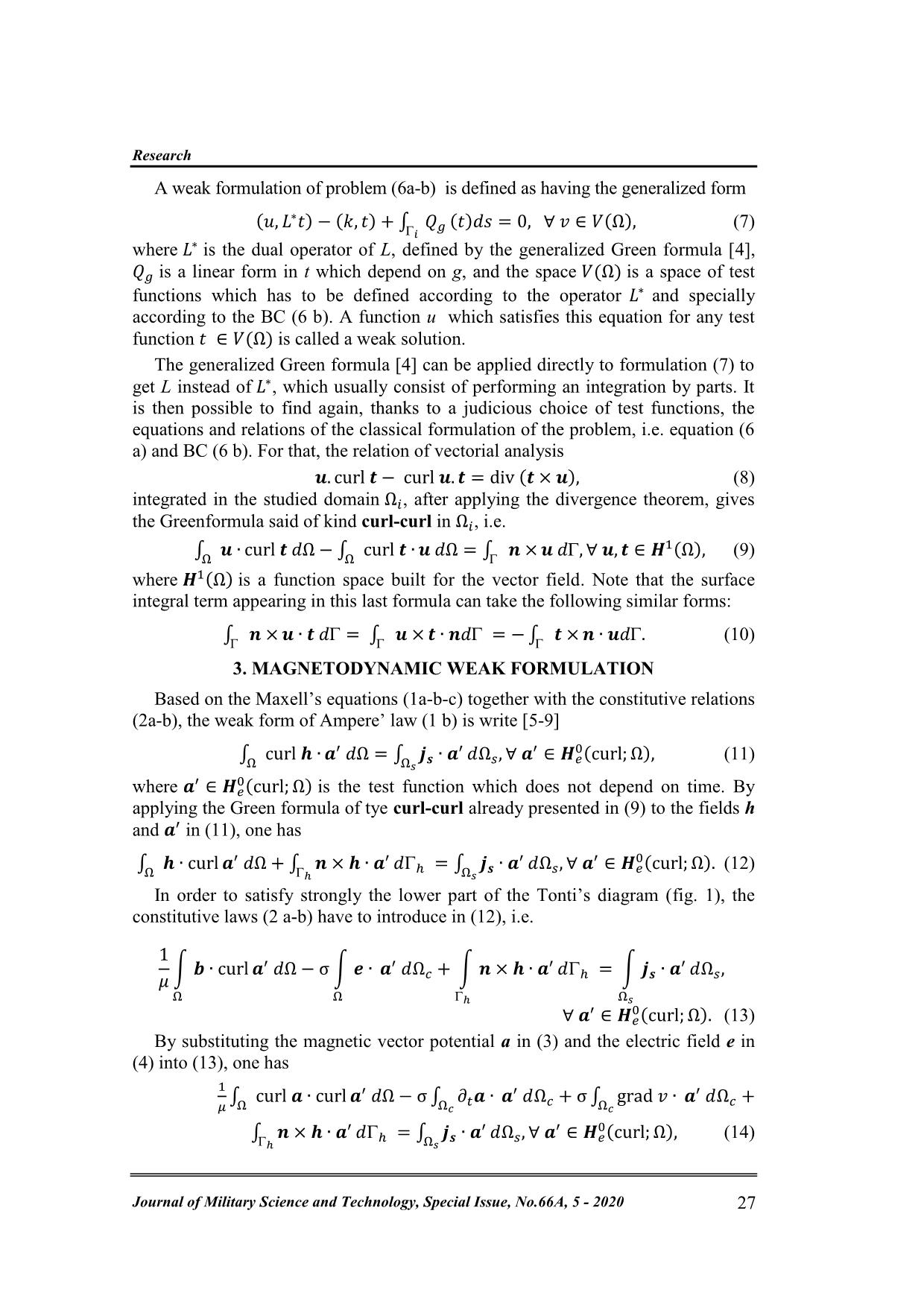
In order to scope with this challenge, in this paper, we introduce a finite element
method (FEM) [3] for taking leakage and fringing fluxes of the magnetic circuits
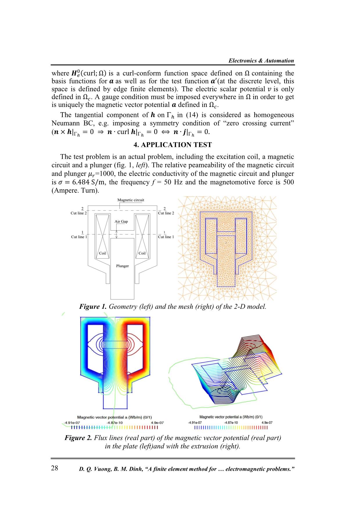
into account. The goal of this research is not to construct physical theories of the
method, but to use these theories to calculate accurate distributions of magnetic
flux densities and eddy current losses with air-gap variations of the magnetic
circuits. The method is validated on a practical test problem.
Trang 1
Trang 2
Trang 3
Trang 4
Trang 5
Trang 6
Trang 7
Tóm tắt nội dung tài liệu: A finite element method for modeling of electromagnetic problems
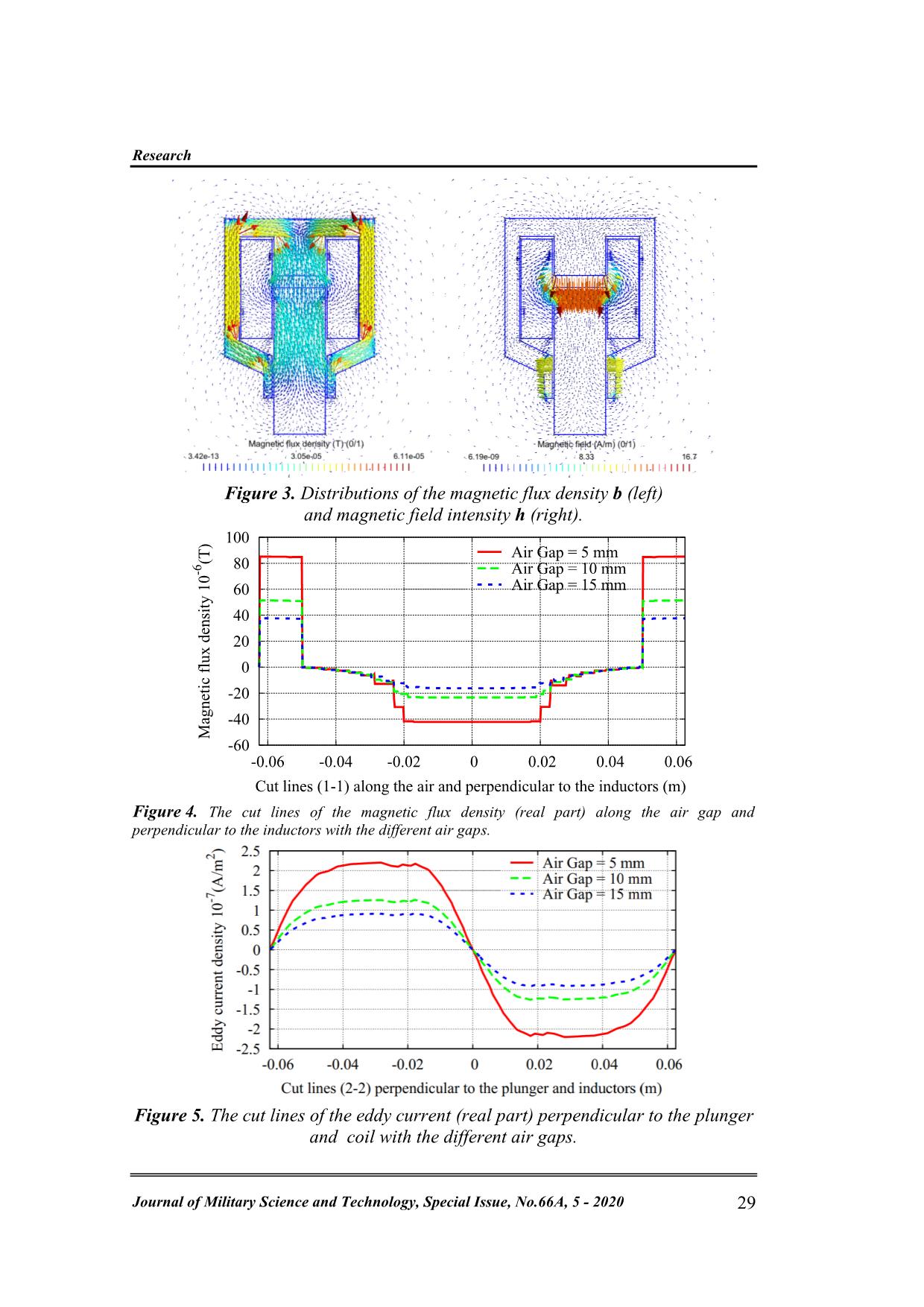
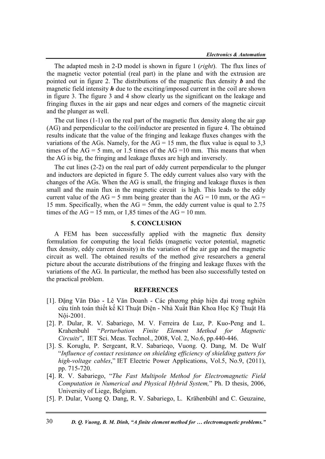
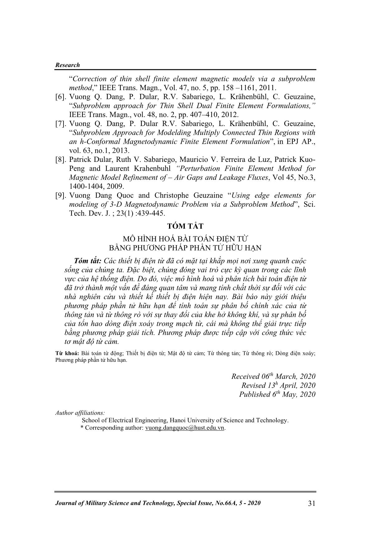
This paper introduces a finite element method to compute accurate distributions of leakage and fringing fluxes with air-gap variations, and eddy current losses of the magnetic circuits, that cannot generally be solved by a direct analytic method. The method is approached for the magnetic flux density formulation. Keywords: Magnetodynamics; Electromagnetic devices; Magnetic flux density; Leakage flux; Fringing flux; Eddy current losses; Finite element method. 1. INTRODUCTION As we have known, all classical electromagnetic phenomena are presented by Maxwell’s equations together with constitutive material laws. These equations are partial differential equation associated with the magnetic fields and their sources. The direct application of the analytic method for solving these models is really difficult or even not possible [1]. Moreover, if possible, the obtained results from this method often has great inaccuracies because of the neglecting of leakage and fringing fluxes at the air gap of the magnetic circuits in the studied problem. In [2], many authors have been used a perturbation finite element methods for magnetic circuits. In order to scope with this challenge, in this paper, we introduce a finite element method (FEM) [3] for taking leakage and fringing fluxes of the magnetic circuits into account. The goal of this research is not to construct physical theories of the method, but to use these theories to calculate accurate distributions of magnetic flux densities and eddy current losses with air-gap variations of the magnetic circuits. The method is validated on a practical test problem. 2. DEFINTITION OF MAGNETODYNAMIC PROBLEMS 2.1. Theory of the magnetodynamic problem In this problem, the characteristic size of the studied domain Ω with boundary 𝜕Ω = Γ = Γh ∪ Γe, is considered much less than the wave-length λ = 𝑐/𝑓 in each medium. Hence, the displacement current density is negligible. The Maxwell’s equations together with the following constitutive relations [2-6] curl 𝒆 = −𝜕𝑡𝒃, curl 𝒉 = 𝒋𝑠, div𝒃 = 0, (1a-b-c) with behavior relations of materials, i.e. 𝒃 = 𝜇𝒉, 𝒋 = 𝜎𝒆, (2a-b) where 𝒃 is the magnetic flux density, 𝒉 is the magnetic field, 𝒆 is the electric field, 𝜇 is the magnetic permeability, 𝜎 is the electric conductivity, 𝒋 is the eddy current density belonged to the conducting part Ω𝑐 (Ω𝑐 ⊂ Ω) , and 𝒋𝑠 is the imposed Electronics & Automation D. Q. Vuong, B. M. Dinh, “A finite element method for electromagnetic problems.” 26 electric current density defined in the non-conducting Ω𝑐 𝐶, with Ω𝑐 = Ω𝑐 ∪ Ω𝑐 𝐶. Equations in (1 a) and (1 b) are to be solved with the boundary conditions (BCs) that the tangential component of the magnetic field on BC 𝒏 × 𝒉|Γ𝑒, for n being the unit normal exterior to Ω. The magnetic flux density b in (1 c) can be derived from magnetic vector potential a such that 𝒃 = curl 𝒂. (3) Combining equation (3) with (1 a), one gets curl (𝒆 + 𝜕𝑡𝒂) = 0, that leads to the definition of an electric scalar potential 𝑣, i.e. 𝒆 = −(𝜕𝑡𝒂 + grad 𝑣). (4) The field a in (3) is not unique because its divergence is not specified. Thus, a gauge condition has to imposed to obtained the unique solution of a. In addition, an implicit gauge in conduction regions is given by setting 𝑣 to zero everywhere in the Ω𝑐. Hence, essential BC is defined as 𝒏 × 𝒂|Γ𝑒 = 0, (5) which implies 𝒏 ∙ 𝒃|Γ𝑒 = 0. This means that the field b is always unique even if a is not. The magnetodynamic problem is herein suitable with the Tonti’s diagram [4]. That means that the unknown fields 𝒉 ∈ 𝑯ℎ (curl; Ω) , 𝒋 ∈ 𝑯ℎ (div; Ω ) , 𝒃 ∈ 𝑯𝑒 (curl; Ω ). Where the function spaces (𝑯ℎ (curl; Ω) and 𝑯𝑒 (dive; Ω)) contain the BCs applicable to the fields on the complementary parts Γℎ and Γ𝑒 of the studied domain Ω. Thus, Tonti’s diagram of the dynamic case is defined as the below diagram [4]: Figure 1. Magnetodynamic Tonti’s diagram [2]. 2.2. Theory of weak formulation A partial differential problem of form is considered as [4] L u = k in Ω, B u = g on 𝜕Ω = Γ, (6a-b) where L is a differential operator of order n, B is an operator which defines a BC, k and g are functions respectively defined in Ω and on its boundary Γ, and u is an unknown function from a function space U and defined in Ω̅, i.e, 𝑢 ∈ U(Ω)̅̅ ̅. Note that f can eventually depend on u. The problem (6a-b) constitutes what is called a classical/strong formulation. A function 𝑢 ∈ U(Ω)̅̅ ̅ which verifies this problem is called a classical/strong solution. In particular, as L is of order n, the function u has to be n-1 times continuously differentiable, i.e. u ∈ 𝐶𝑛−1(Ω). Research Journal of Military Science and Technology, Special Issue, No.66A, 5 - 2020 27 A weak formulation of problem (6a-b) is defined as having the generalized form (𝑢, 𝐿∗𝑡) − (𝑘, 𝑡) + ∫ 𝑄𝑔𝑖 (𝑡)𝑑𝑠 = 0, ∀ 𝑣 ∈ 𝑉(Ω), (7) where 𝐿∗ is the dual operator of L, defined by the generalized Green formula [4], 𝑄𝑔 is a linear form in t which depend on g, and the space 𝑉(Ω) is a space of test functions which has to be defined according to the operator 𝐿∗ and specially according to the BC (6 b). A function u which satisfies this equation for any test function 𝑡 ∈ 𝑉(Ω) is called a weak solution. The generalized Green formula [4] can be applied directly to formulation (7) to get L instead of 𝐿∗, which usually consist of performing an integration by parts. It is then possible to find again, thanks to a judicious choice of test functions, the equations and relations of the classical formulation of the problem, i.e. equation (6 a) and BC (6 b). For that, the relation of vectorial analysis 𝒖. curl 𝒕 − curl 𝒖. 𝒕 = div (𝒕 × 𝒖), (8) integrated in the studied domain Ω𝑖, after applying the divergence theorem, gives the Greenformula said of kind curl-curl in Ω𝑖, i.e. ∫ 𝒖 ∙ Ω curl 𝒕 𝑑Ω − ∫ curl 𝒕 ∙ Ω 𝒖 𝑑Ω = ∫ 𝒏 × 𝒖 𝑑, ∀ 𝒖, 𝒕 ∈ 𝑯1(Ω), (9) where 𝑯1(Ω) is a function space built for the vector field. Note that the surface integral term appearing in this last formula can take the following similar forms: ∫ 𝒏 × 𝒖 ∙ 𝒕 𝑑 = ∫ 𝒖 × 𝒕 ∙ 𝒏𝑑 = − ∫ 𝒕 × 𝒏 ∙ 𝒖𝑑. (10) 3. MAGNETODYNAMIC WEAK FORMULATION Based on the Maxell’s equations (1a-b-c) together with the constitutive relations (2a-b), the weak form of Ampere’ law (1 b) is write [5-9] ∫ curl 𝒉 ∙ Ω 𝒂′ 𝑑Ω = ∫ 𝒋𝒔 ∙ 𝒂 ′ Ω𝑠 𝑑Ω𝑠, ∀ 𝒂 ′ ∈ 𝑯𝑒 0(curl; Ω), (11) where 𝒂′ ∈ 𝑯𝑒 0(curl; Ω) is the test function which does not depend on time. By applying the Green formula of tye curl-curl already presented in (9) to the fields h and 𝒂′ in (11), one has ∫ 𝒉 ∙ curl Ω 𝒂′ 𝑑Ω + ∫ 𝒏 × 𝒉 ∙ 𝒂′ ℎ 𝑑ℎ = ∫ 𝒋𝒔 ∙ 𝒂 ′ Ω𝑠 𝑑Ω𝑠, ∀ 𝒂 ′ ∈ 𝑯𝑒 0(curl; Ω). (12) In order to satisfy strongly the lower part of the Tonti’s diagram (fig. 1), the constitutive laws (2 a-b) have to introduce in (12), i.e. 1 𝜇 ∫ 𝒃 ∙ curl Ω 𝒂′ 𝑑Ω − σ ∫ 𝒆 ∙ Ω 𝒂′ 𝑑Ω𝑐 + ∫ 𝒏 × 𝒉 ∙ 𝒂 ′ ℎ 𝑑ℎ = ∫ 𝒋𝒔 ∙ 𝒂 ′ Ω𝑠 𝑑Ω𝑠, ∀ 𝒂′ ∈ 𝑯𝑒 0(curl; Ω). (13) By substituting the magnetic vector potential a in (3) and the electric field e in (4) into (13), one has 1 𝜇 ∫ curl 𝒂 ∙ curl Ω 𝒂′ 𝑑Ω − σ ∫ 𝜕𝑡𝒂 ∙ Ω𝑐 𝒂′ 𝑑Ω𝑐 + σ ∫ grad 𝑣 ∙ Ω𝑐 𝒂′ 𝑑Ω𝑐 + ∫ 𝒏 × 𝒉 ∙ 𝒂′ ℎ 𝑑ℎ = ∫ 𝒋𝒔 ∙ 𝒂 ′ Ω𝑠 𝑑Ω𝑠, ∀ 𝒂 ′ ∈ 𝑯𝑒 0(curl; Ω), (14) Electronics & Automation D. Q. Vuong, B. M. Dinh, “A finite element method for electromagnetic problems.” 28 where 𝑯𝑒 0(curl; Ω) is a curl-conform function space defined on Ω containing the basis functions for 𝒂 as well as for the test function 𝒂′(at the discrete level, this space is defined by edge finite elements). The electric scalar potential 𝑣 is only defined in Ω𝑐. A gauge condition must be imposed everywhere in Ω in order to get is uniquely the magnetic vector potential 𝒂 defined in Ω𝑐. The tangential component of 𝒉 on ℎ in (14) is considered as homogeneous Neumann BC, e.g. imposing a symmetry condition of “zero crossing current” (𝒏 × 𝒉|ℎ = 0 ⇒ 𝒏 ∙ curl 𝒉|ℎ = 0 ⟺ 𝒏 ∙ 𝒋|ℎ = 0. 4. APPLICATION TEST The test problem is an actual problem, including the excitation coil, a magnetic circuit and a plunger (fig. 1, left). The relative peameability of the magnetic circuit and plunger 𝜇𝑟=1000, the electric conductivity of the magnetic circuit and plunger is 𝜎 = 6.484 S/m, the frequency f = 50 Hz and the magnetomotive force is 500 (Ampere. Turn). Figure 1. Geometry (left) and the mesh (right) of the 2-D model. Figure 2. Flux lines (real part) of the magnetic vector potential (real part) in the plate (left)and with the extrusion (right). Research Journal of Military Science and Technology, Special Issue, No.66A, 5 - 2020 29 Figure 3. Distributions of the magnetic flux density b (left) and magnetic field intensity h (right). Figure 4. The cut lines of the magnetic flux density (real part) along the air gap and perpendicular to the inductors with the different air gaps. Figure 5. The cut lines of the eddy current (real part) perpendicular to the plunger and coil with the different air gaps. -60 -40 -20 0 20 40 60 80 100 -0.06 -0.04 -0.02 0 0.02 0.04 0.06 M ag n et ic f lu x d en si ty 1 0 -6 (T ) Cut lines (1-1) along the air and perpendicular to the inductors (m) Air Gap = 5 mm Air Gap = 10 mm Air Gap = 15 mm Electronics & Automation D. Q. Vuong, B. M. Dinh, “A finite element method for electromagnetic problems.” 30 The adapted mesh in 2-D model is shown in figure 1 (right). The flux lines of the magnetic vector potential (real part) in the plane and with the extrusion are pointed out in figure 2. The distributions of the magnetic flux density b and the magnetic field intensity h due to the exciting/imposed current in the coil are shown in figure 3. The figure 3 and 4 show clearly us the significant on the leakage and fringing fluxes in the air gaps and near edges and corners of the magnetic circuit and the plunger as well. The cut lines (1-1) on the real part of the magnetic flux density along the air gap (AG) and perpendicular to the coil/inductor are presented in figure 4. The obtained results indicate that the value of the fringing and leakage fluxes changes with the variations of the AGs. Namely, for the AG = 15 mm, the flux value is equal to 3,3 times of the AG = 5 mm, or 1.5 times of the AG =10 mm. This means that when the AG is big, the fringing and leakage fluxes are high and inversely. The cut lines (2-2) on the real part of eddy current perpendicular to the plunger and inductors are depicted in figure 5. The eddy current values also vary with the changes of the AGs. When the AG is small, the fringing and leakage fluxes is then small and the main flux in the magnetic circuit is high. This leads to the eddy current value of the AG = 5 mm being greater than the AG = 10 mm, or the AG = 15 mm. Specifically, when the AG = 5mm, the eddy current value is qual to 2.75 times of the AG = 15 mm, or 1,85 times of the AG = 10 mm. 5. CONCLUSION A FEM has been successfully applied with the magnetic flux density formulation for computing the local fields (magnetic vector potential, magnetic flux density, eddy current density) in the variation of the air gap and the magnetic circuit as well. The obtained results of the method give researchers a general picture about the accurate distributions of the fringing and leakage fluxes with the variations of the AG. In particular, the method has been also successfully tested on the practical problem. REFERENCES [1]. Đặng Văn Đào - Lê Văn Doanh - Các phương pháp hiện đại trong nghiên cứu tính toán thiết kế Kĩ Thuật Điện - Nhà Xuất Bản Khoa Học Kỹ Thuật Hà Nội-2001. [2]. P. Dular, R. V. Sabariego, M. V. Ferreira de Luz, P. Kuo-Peng and L. Krahenbuhl “Perturbation Finite Element Method for Magnetic Circuits”, IET Sci. Meas. Technol., 2008, Vol. 2, No.6, pp.440-446. [3]. S. Koruglu, P. Sergeant, R.V. Sabarieqo, Vuong. Q. Dang, M. De Wulf “Influence of contact resistance on shielding efficiency of shielding gutters for high-voltage cables,” IET Electric Power Applications, Vol.5, No.9, (2011), pp. 715-720. [4]. R. V. Sabariego, “The Fast Multipole Method for Electromagnetic Field Computation in Numerical and Physical Hybrid System,” Ph. D thesis, 2006, University of Liege, Belgium. [5]. P. Dular, Vuong Q. Dang, R. V. Sabariego, L. Krähenbühl and C. Geuzaine, Research Journal of Military Science and Technology, Special Issue, No.66A, 5 - 2020 31 “Correction of thin shell finite element magnetic models via a subproblem method,” IEEE Trans. Magn., Vol. 47, no. 5, pp. 158 –1161, 2011. [6]. Vuong Q. Dang, P. Dular, R.V. Sabariego, L. Krähenbühl, C. Geuzaine, “Subproblem approach for Thin Shell Dual Finite Element Formulations,” IEEE Trans. Magn., vol. 48, no. 2, pp. 407–410, 2012. [7]. Vuong Q. Dang, P. Dular R.V. Sabariego, L. Krähenbühl, C. Geuzaine, “Subproblem Approach for Modelding Multiply Connected Thin Regions with an h-Conformal Magnetodynamic Finite Element Formulation”, in EPJ AP., vol. 63, no.1, 2013. [8]. Patrick Dular, Ruth V. Sabariego, Mauricio V. Ferreira de Luz, Patrick Kuo- Peng and Laurent Krahenbuhl “Perturbation Finite Element Method for Magnetic Model Refinement of – Air Gaps and Leakage Fluxes, Vol 45, No.3, 1400-1404, 2009. [9]. Vuong Dang Quoc and Christophe Geuzaine “Using edge elements for modeling of 3-D Magnetodynamic Problem via a Subproblem Method”, Sci. Tech. Dev. J. ; 23(1) :439-445. TÓM TẮT MÔ HÌNH HOÁ BÀI TOÁN ĐIỆN TỪ BẰNG PHƯƠNG PHÁP PHẦN TỬ HỮU HẠN Tóm tắt: Các thiết bị điện từ đã có mặt tại khắp mọi nơi xung quanh cuộc sống của chúng ta. Đặc biệt, chúng đóng vai trò cực kỳ quan trong các lĩnh vực của hệ thống điện. Do đó, việc mô hình hoá và phân tích bài toán điện từ đã trở thành một vấn đề đáng quan tâm và mang tính chất thời sự đối với các nhà nghiên cứu và thiết kế thiết bị điện hiện nay. Bài báo này giới thiệu phương pháp phần tử hữu hạn để tính toán sự phân bố chính xác của từ thông tản và từ thông rò với sự thay đổi của khe hở không khí, và sự phân bố của tổn hao dòng điện xoáy trong mạch từ, cái mà không thể giải trực tiếp bằng phương pháp giải tích. Phương pháp được tiếp cập với công thức véc tơ mật độ từ cảm. Từ khoá: Bài toán từ động; Thiết bị điện từ; Mật độ từ cảm; Từ thông tản; Từ thông rò; Dòng điện xoáy; Phương pháp phần tử hữu hạn. Received 06th March, 2020 Revised 13h April, 2020 Published 6th May, 2020 Author affiliations: School of Electrical Engineering, Hanoi University of Science and Technology. * Corresponding author: vuong.dangquoc@hust.edu.vn.
File đính kèm:
 a_finite_element_method_for_modeling_of_electromagnetic_prob.pdf

